Downloaded 698 times

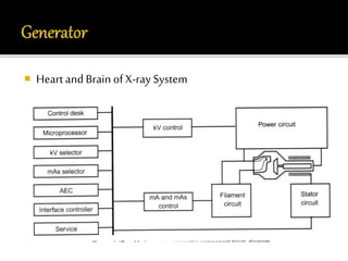
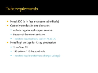
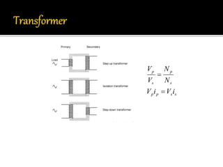
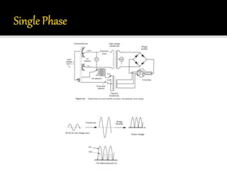
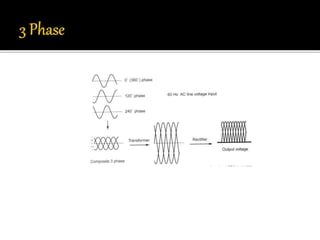
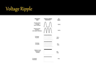
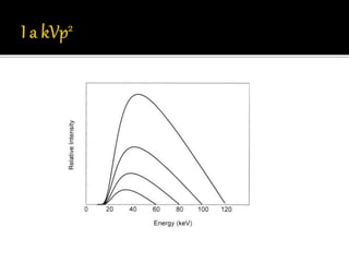
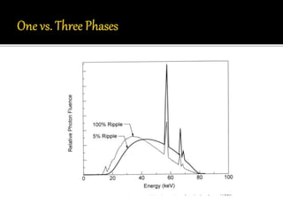
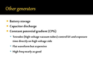
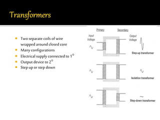
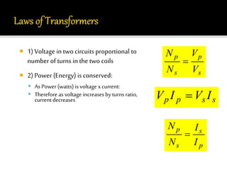
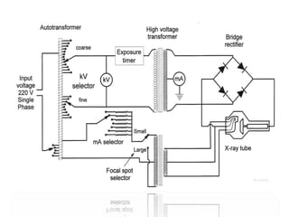
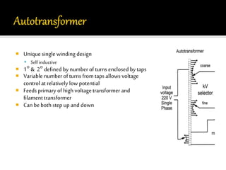
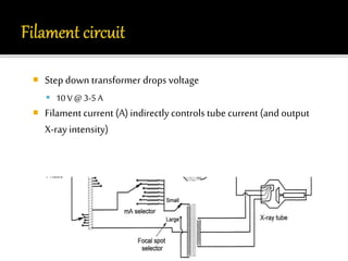
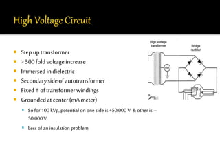
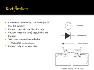
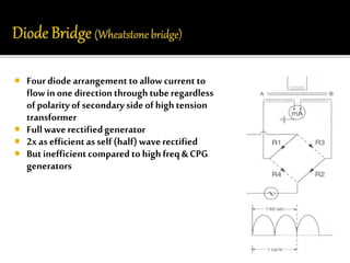
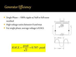
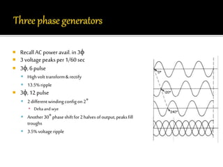
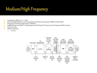
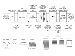
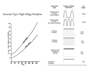
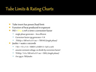

This document discusses key components of X-ray systems, including vacuum tube diodes that require rectification to convert AC to DC, high voltage transformers to achieve the voltages needed for X-ray production, and various generator designs like single phase, three phase, and constant potential generators. It also covers topics like transformer configurations and efficiencies, rectification circuits, and factors that determine the maximum safe output of X-ray tubes.


