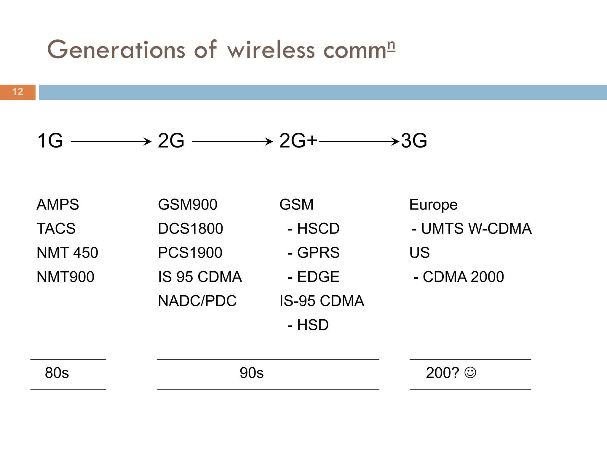
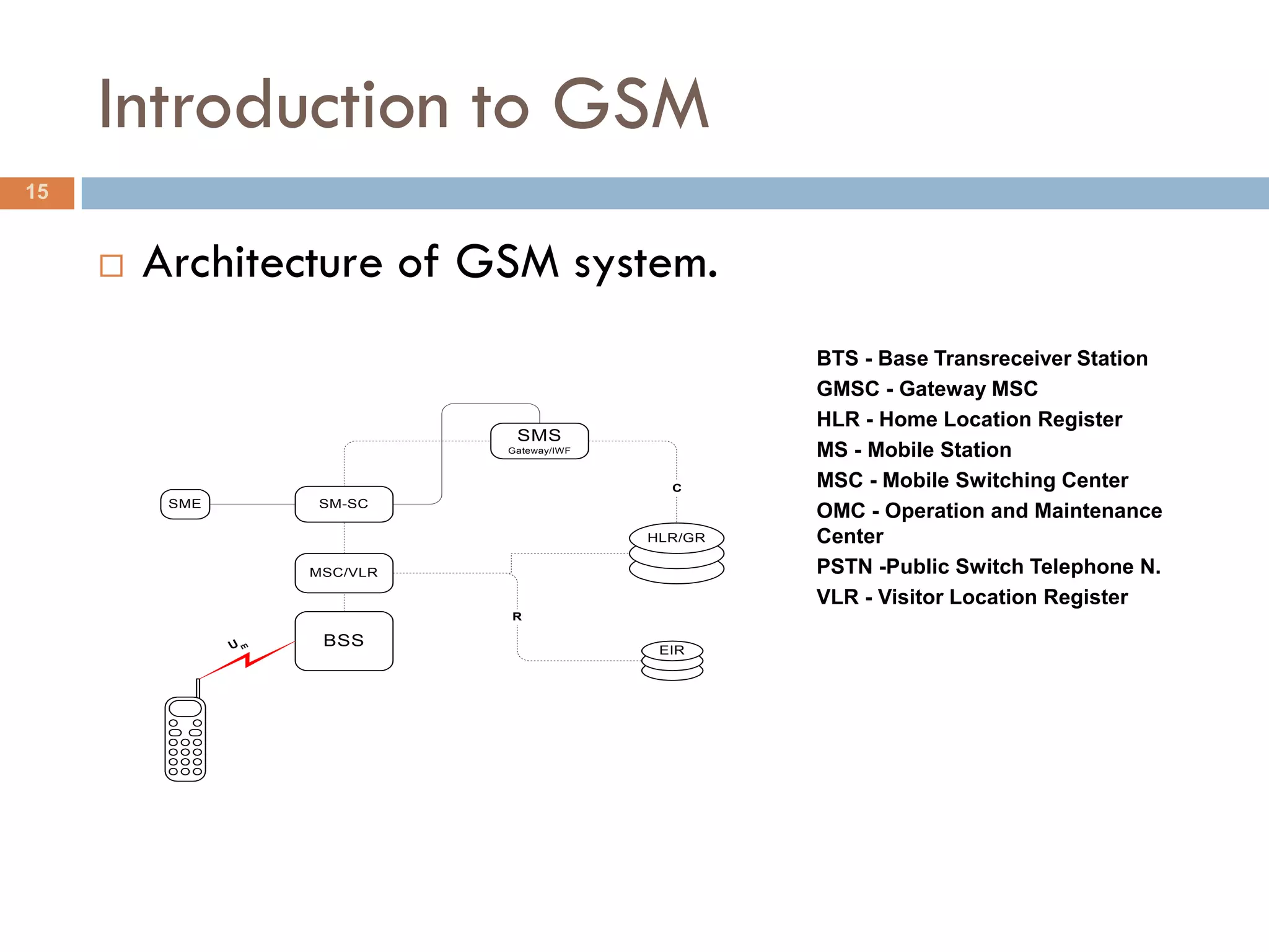
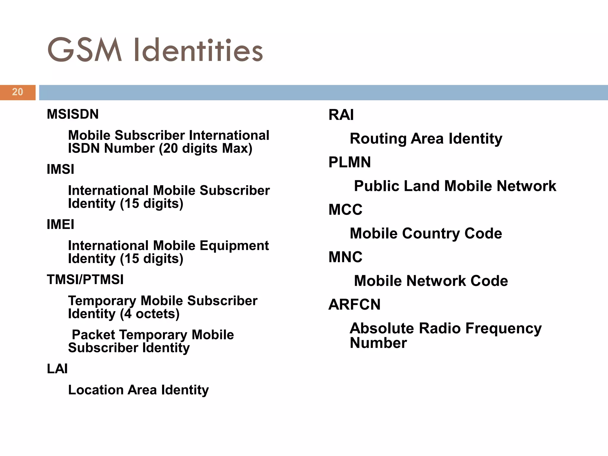
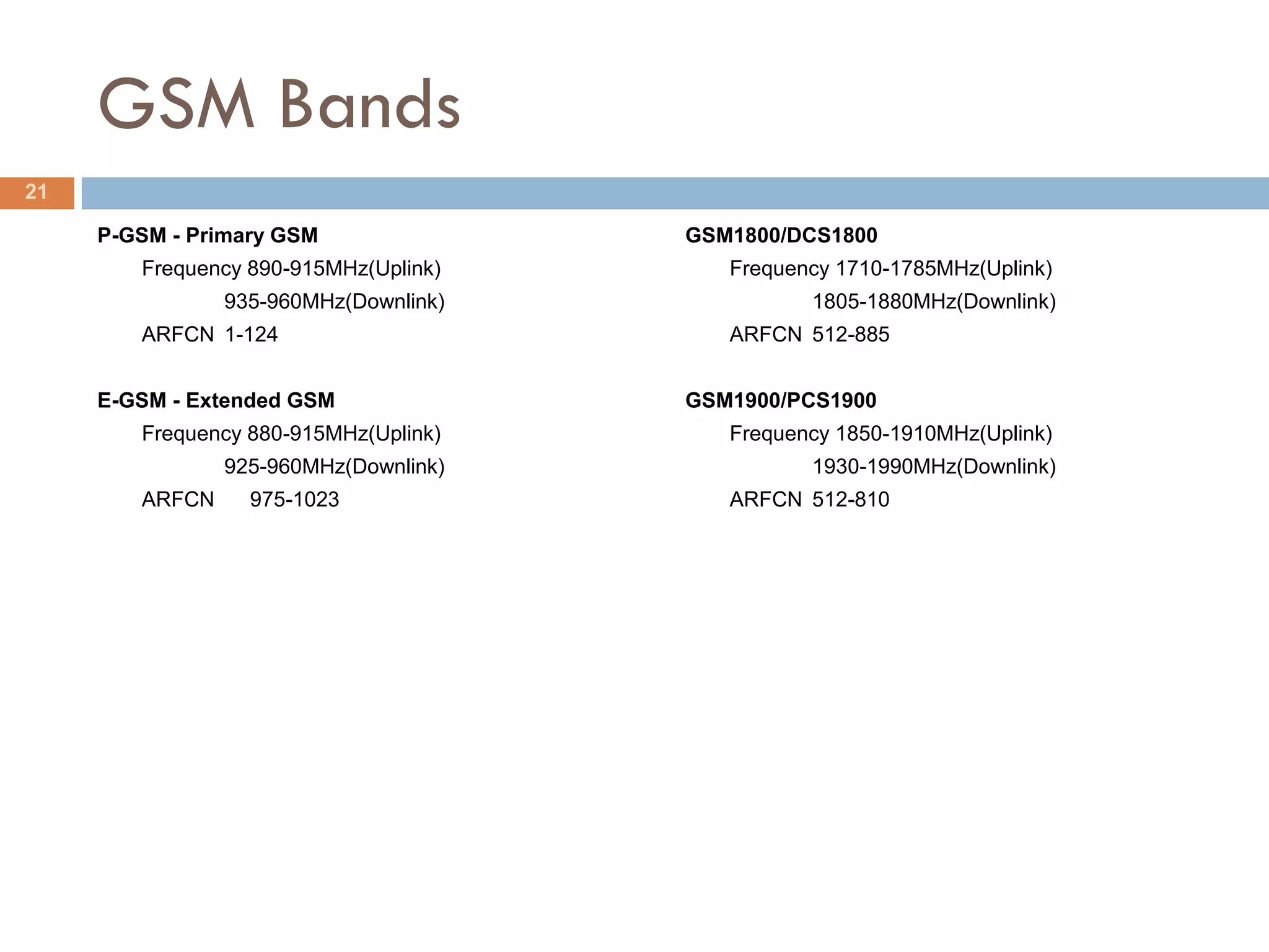
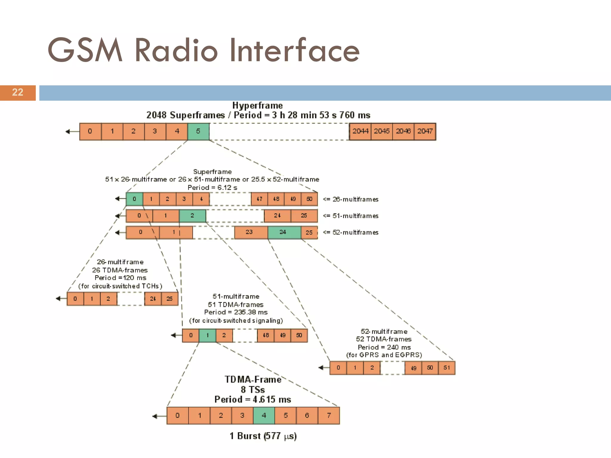
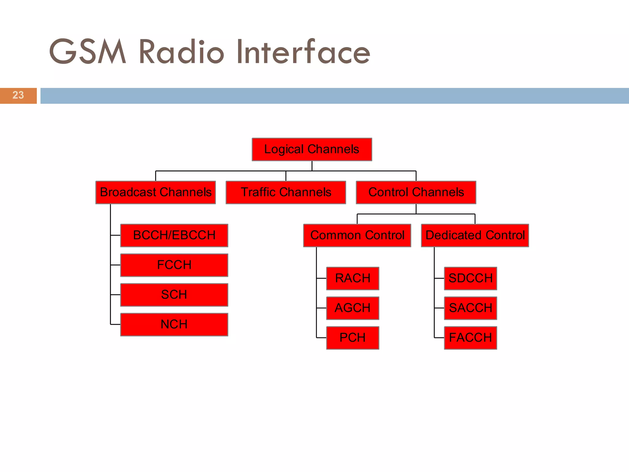
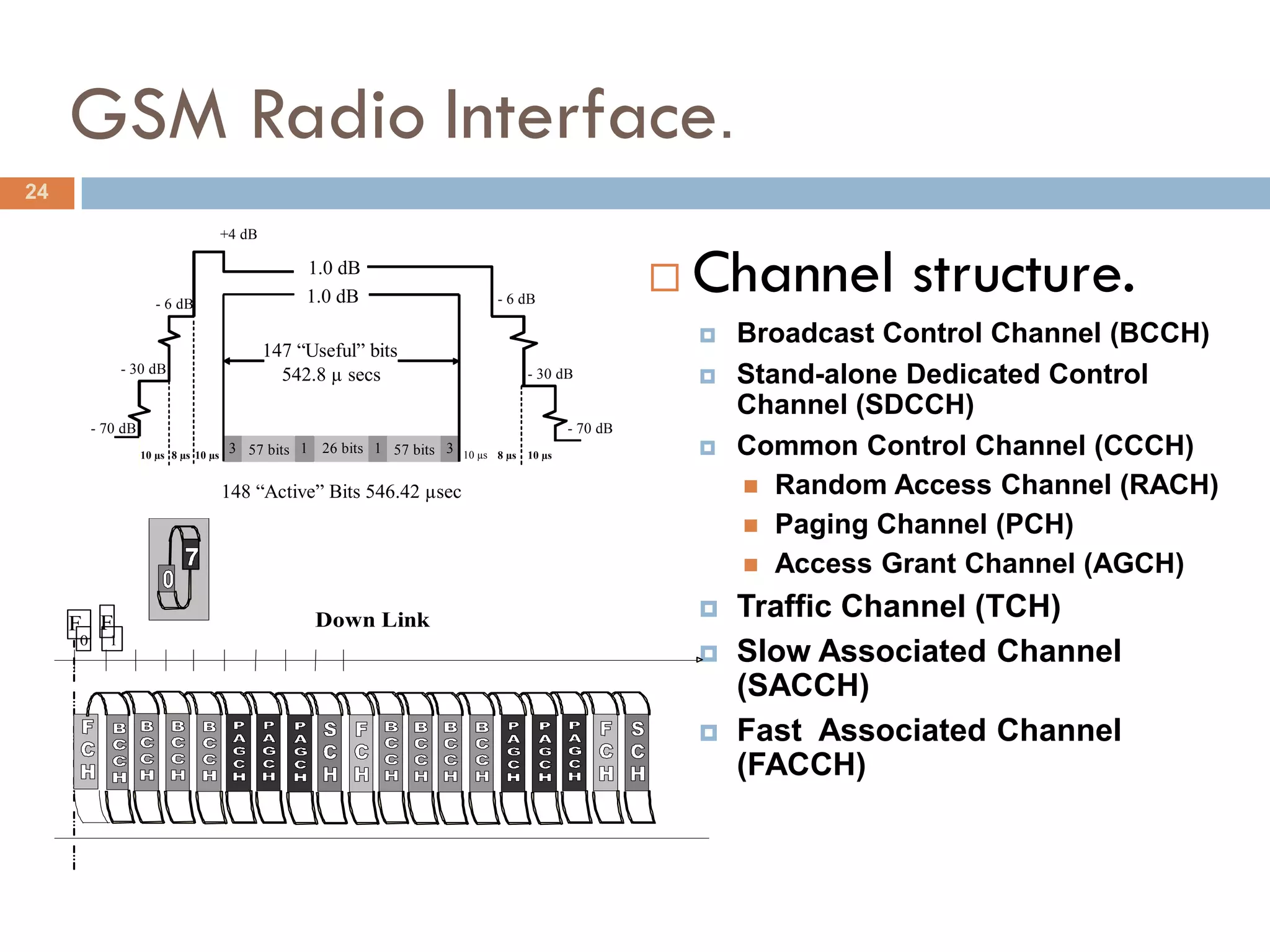
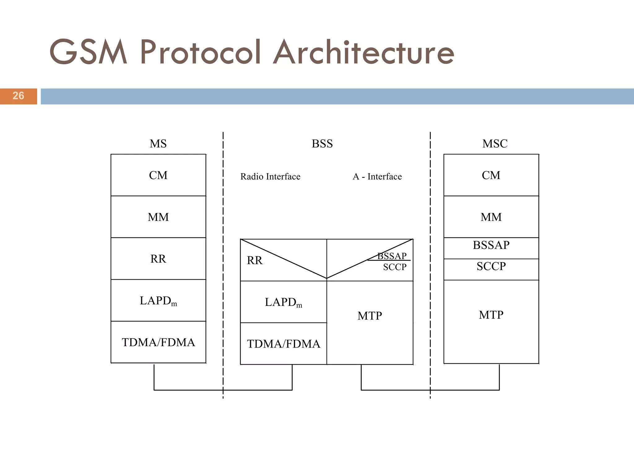
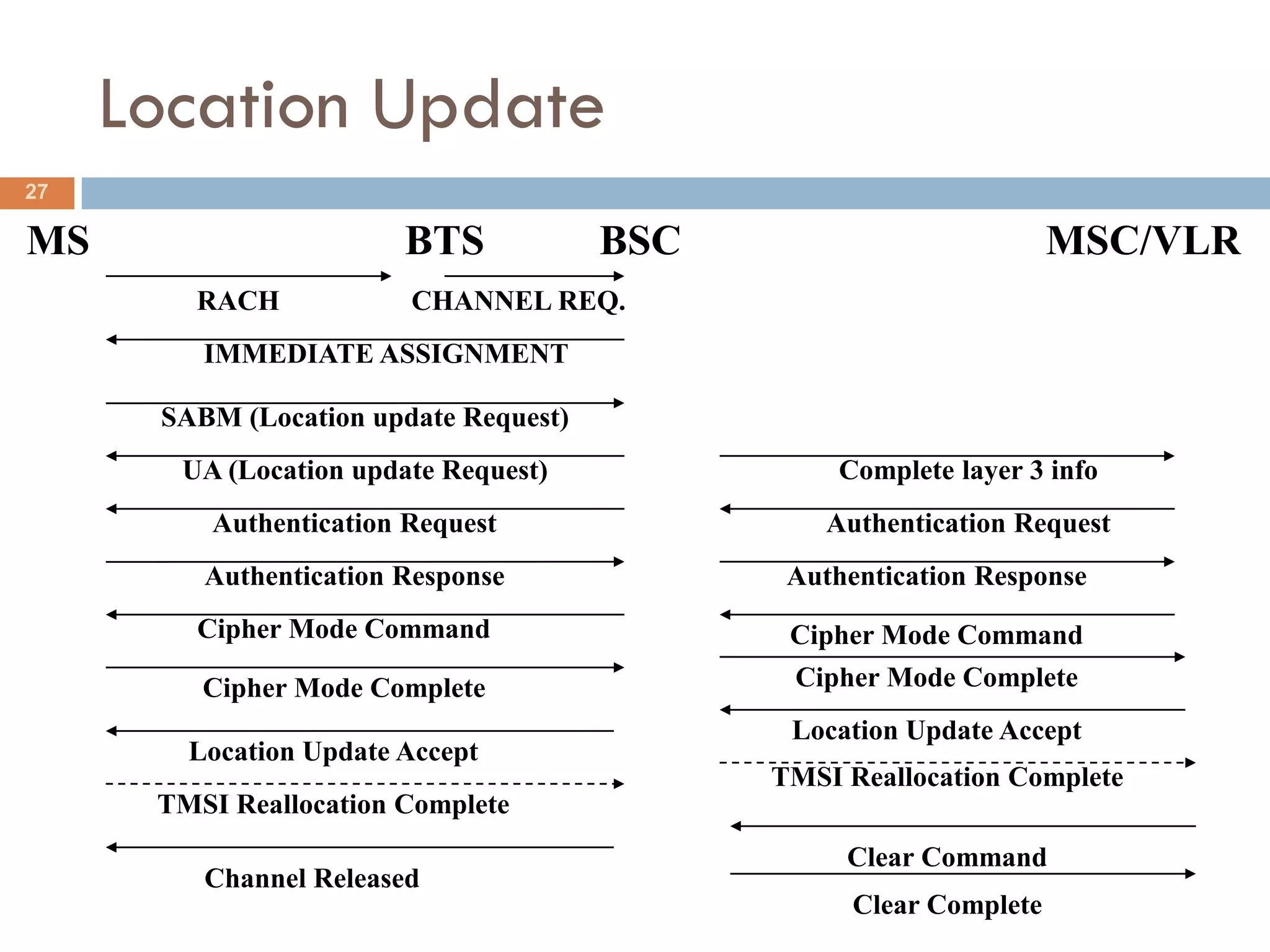
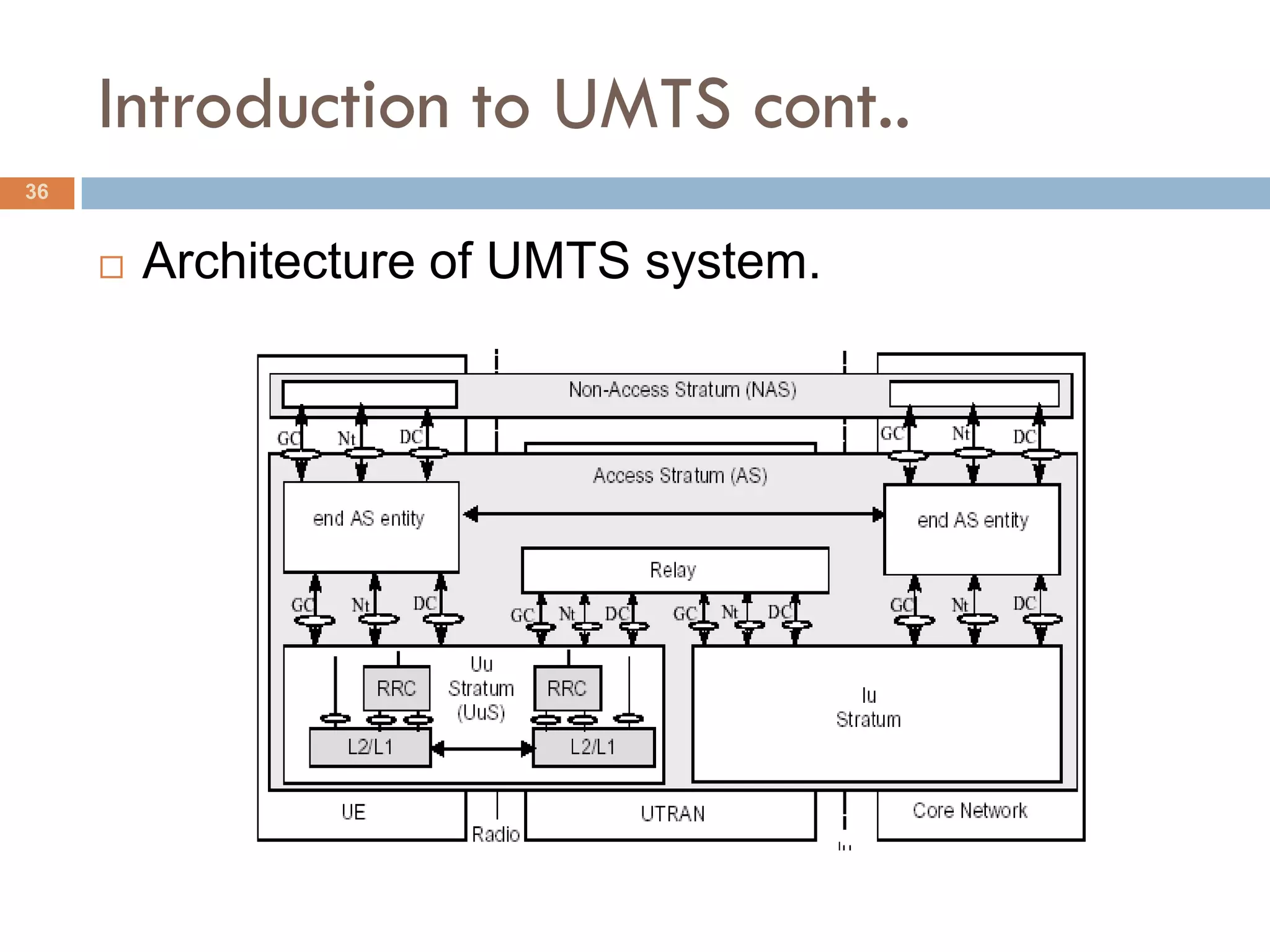
The document discusses wireless communication systems from first to third generation. It covers:
- The basics of wireless communication including terminology like bandwidth and protocols.
- Cellular concepts such as why cells are used, their shapes, frequency allocation, and calculating cell capacity.
- The generations of wireless including 1G, 2G, 2.5G, and 3G and their characteristics.
- An introduction to GSM including its architecture, identities, bands, radio interface, and security features.
Performance analysis of Multiband - OFDM systems using LDPC coder in pulsed -...IDES Editor
In this paper, a combined approach where low density
parity check (LDPC) codes are used to reduce the complexity
and power consumption of pulsed orthogonal frequencydivision
multiplexing (pulsed-OFDM) ultra-wideband (UWB)
systems is described. The proposed system uses LDPC codes
to achieve higher code rates without using convolution
encoding and puncturing thereby reducing the complexity and
power consumption of pulsed-OFDM system. The LDPCpulsed-
OFDM system achieves channel capacity with different
code rates and has good performance in different channel
fading scenarios. The pulsed OFDM system is used where
pulsed signals could spread the frequency spectrum of the
OFDM signal. The performance of LDPC-pulsed-OFDM
system for wireless personal area networks (WPAN) is
analyzed for different UWB indoor propagation channels (CM3
and CM4) provided by the IEEE 802.15.3a Standard activity
committee. To establish this, a design of LDPC-pulsed-OFDM
system using the digital video broadcasting-satellite-second
generation (DVB-S2) standard and provide the simulation
results for the different code rates supported by LDPC codes
is presented.
Integrated DWDM and MIMO-OFDM System for 4G High Capacity Mobile Communicatio...CSCJournals
Dense wavelength-division multiplexing (DWDM) technique is a very promising data transmission technology for utilizing the capacity of the fiber. By DWDM, multiple signals (video, audio, data etc) staggered in wavelength domain can be multiplexed and transmitted down the same fiber. The Multiple-input multiple-output (MIMO) wireless technology in combination with orthogonal frequency division multiplexing (MIMO-OFDM) is an attractive air-interface solution for next-generation wireless local area networks (WLANs) and fourth-generation mobile cellular wireless systems. This article provides an overview of the integrated DWDM MIMO-OFDM technology and focuses on DWDM transmitter design with adequate dispersion compensation for high data rate of 10Gbps ,MIMO-OFDM system design, space-time coded signaling, receiver design and performance analysis in terms of bit error rate for Integrated system. The simulation is carried out using powerful software tools Optisystem and MATLAB . In this paper a 64 channel DWDM system is simulated for transmission of baseband NRZ signal over fiber. Each of the transmission is at bit rate of 10 Gbps leading to high data rate transmission of 640 Gbps.The resultant Bit Error Rate(BER) is in the range 10-12 for DWDM system which is given as input to MIMO-OFDM system..This system performance is analyzed in terms of BER with SNR for Rayleigh, and AWGN channels and BER of 10-4 is achieved at SNR of 10dbs
Successful interference cancellation with Blind Equalization method for MC-CD...IJTET Journal
Abstract— The increasing demand for wireless services has created the need for cost effective transmission techniques that can exploit scarce spectral resources efficiently. Inorder to achieve the high data rates needed to meet the quality of service requirements of future multimedia applications, MC-CDMA has been considered as good air-interface candidate, especially for the downlink. However, the user capacity of MC-CDMA system is essentially limited by interference. This interference can be mitigated by employing precoding techniques, IB-DFE based receivers and other efficient interference suppression techniques. In the proposed system, combined Iterative IA precoding at the transmitter with IB-DFE based processing at the receiver is suggested for MC-CDMA systems. The matrices for this nonlinear space-frequency equalizer are obtained by minimizing the overall MSE of all data streams at each subcarrier.
EFFECTS OF FILTERS ON THE PERFORMANCE OF DVB-T RECEIVERijwmn
Digital Video Broadcasting-Terrestrial (DVB-T) is an international standard for digital television
services. Orthogonal Frequency Division Multiplexing (OFDM) is the core of this technology. OFDM
based system like DVB-T can handle multipath fading and hence it can minimize Inter Symbol
Interference (ISI). DVB-T has some limitations too namely large dynamic range of the signals and
sensitivity to frequency error. In order to overcome these limitations DVB-T receivers should be optimally
designed. In this paper we address the issues related to optimal DVB-T receiver design. There of several
signal processing units in a DVB-T receiver. A low-pass filter is one of them. In this paper, we consider
some classic filters namely Butterworth, Chebyshev, and elliptic in the DVB-T receiver. The effects of
different filters on the performances of DVB-T receiver have been investigated and compared in this
paper under AWGN channel condition
This ppt covers the following topics:
Structural evolution of cellular communications;
Frequency reuse;
Duplex techniques;
Multiple-access/broadcasting techniques;
Handover (handoff);
Multi-cell cooperation/processing;
Resource allocation;
Cognitive radios;
MIMO and massive MIMO;
Distributed antenna wireless communications;
Cellular social networks.
orthogonal frequency division multiplexing(OFDM)
its orthogonal frequency multiplexing topic basicallly in digital signal processing , network signal and system , it also helpful in engineering course either electrical or electronics and communication engineering.
OFDM allows tightly packed carriers to convey information orthogonally and with high bandwidth efficiency
Objectives Description:
Concepts
Basic idea
Introduction to OFDM
Implementation
Advantages and Drawbacks.
FDMA
PERFORMANCES OF ORTHOGONAL WAVELET DIVISION MULTIPLEX (OWDM) SYSTEM UNDER AWG...IJCNCJournal
Orthogonal Wavelet Division Multiplexing (OWDM) has been considered as an alternative of Orthogonal
Frequency Division Multiplexing (OFDM) in the recent years. OWDM has lower computational complexity
and higher flexibility compared to its OFDM counterpart. The core component of OWDM is wavelet.
Wavelet has been a much investigated and applied topic in digital image processing for a long time.
Recently, it has drawn considerable attention of the researchers working in communication field. In this
work we investigate the performances of OWDM under different channel conditions. We consider three
channel conditions namely Additive White Gaussian Noise (AWGN), Rayleigh, Ricean, and frequency
selective. We consider a number of wavelets namely Haar, Daubechies, Biorthogonal, Reverse
Biorthogonal, Coiflets, and Symlets in OWDM design. For system model we choose Digital Video
Broadcasting-Terrestrial (DVB-T). Originally DVB-T system was designed based on OFDM. In this work
we use OWDM instead. The simulation results show OWDM outperforms OFDM in terms of bit error rate
(BER), noise resiliency, and peak-to-average ration. The results also show that the Haar wavelet based
OWDM outperforms other wavelets based OWDM system under all three considered three channel
conditions.
It is prepared for simple presentation. Focused on basic optical fiber communication. And contains some important information about Space Division Multiplexing Technique.
Performance Analysis of OFDM in Combating Multipath FadingIOSR Journals
Mobile Communication system has been on high rampage for high data transmission over wireless
medium with various challenges caused by the transmission Channel. OFDM is been discovered in recent years
to deal with this problems because of its ability to elegantly cope with multipath interference. This paper
investigates the performance of different modulation schemes using M-ary Phase Shift Keying (M-PSK) and Mary
Quadrature Amplitude Modulation (M-QAM) in information transmission with OFDM technique over Ideal
channel AWGN and worst channel Rayleigh Fading channel in terms of Bits Error Rate (BER). Analysis was
made for different types of modulation schemes BPSK, QPSK, 4-QAM and 16-QAM gray coded bit mapping.
Also, a feasibility of OFDM been used to combat multipath fading was analyzed with comparison between a
single carrier technique and OFDM multicarrier technique. Variation between SNR results with respect to BER
is plotted to show the trade off differences between the modulation schemes with the result showing that OFDM
allows data transmission with minimal error over fading channel than a Single Carrier
Coverage of WCDMA Network Using Different Modulation Techniques with Soft and...ijcnac
The wideband code division multiple access (WCDMA) based 3G cellular mobile
wireless networks are expected to provide a diverse range of multimedia services to
mobile users with guaranteed quality of service (QoS). To serve diverse quality of service
requirements of these networks it necessitates new radio resource management strategies
for effective utilization of network resources with coding schemes. In this paper coverage
area for voice traffic and with different modulation techniques, coding schemes and
decision decoder are discussed. These discussions are to improve the coverage area in
the mobile communication system. This paper is mainly focuses on coverage area of
WCDMA system using link budget calculation with different modulation, coding schemes
and decision decoder. Simulation results demonstrate coverage extension for voice
service with different modulation,coding scheme, soft and hard decision decoder using
appropriate Bit error rate (BER) to maintain QoS of the voice.
GSM is the globel system of organation . It consists of
M.S,BSC MSC ,OMC,FIXED Phone.Mobile station is carried by
the subscriber.and base station subsystem control the radio
link with mobile station . The main part of system is
mobile switching center perform switching of calls between
the mobile and fixed or mobile network use. and operational
and maintainence center oversees the proper operation and
set up of the network. The MS and BSC communicate across
the um link or air interface and BSC&MSC communicate across
A interface.
2. Contents
2
Type of wireless services.
Basics of wireless communication.
Cellular Concepts.
Generations of wireless communication.
Introduction to GSM.
GSM Radio Interface.
Introduction to GPRS.
GPRS Channel Structure
3. Contents cont..
3
Introduction to UMTS
UTRAN Channel structure.
Comparison between 2G,2G+ and 3G
4. Type of wireless services
4
Outdoor Mobile Communication.
– E.g. cellular telephony, WLL etc.
Outdoor Fixed Communication
– E.g. Television broadcast .
Indoor ( Wireless LAN)
– E.g. IEEE 802.11
Satellite Mobile
– E.g. Thuraya, Inmarset etc.
6. Some Basic Terminology
6
Bandwidth
A signal is normally compose of a
range of frequencies. This range of
frequency occupied by the signal is
termed as its BandWidth.
Channel
In communication, the term channel
refers to the communication path
between the two devices. It can refer
to a physical medium or to a set of
properties which distinguishes one
channel from other.
Protocol
A set of rules that govern the
operation of functional units to
achieve communication
7. Access Technologies
7
TDMA CDMA
Time Division Multiple Access Code Division Multiple Access
FDMA
Frequency Division Multiple
Access
F F F
r r r
e e e
q q q
u u u
e e e
n n n
c c c
y y y
Time Time Time
TDMA FDMA CDMA
8. Cellular Concepts
8
Why Cells?
What shape and why?
How to allocate
frequencies?
What is cell capacity?
How it is calculated?
9. Cellular Concepts Contd..
9
Why Cells ?
Each Call Require Pair of RF Channel.
Need to server big community networks.
Radio spectrum available is limited.
Reuse of frequencies required.
What shape and why?
Cells in cellular system is drawn as hexagons.
Actual cell takes different shapes.
Bigger cell for low subscriber density.
Smaller cell for high subscriber density.
On highways cells are optimized to cover length.
10. Cellular Concepts Contd..
10
How to allocate
frequencies?
Split number of channels into
groups
Assigns Frequency in each
group to a cell.
Group cells into cluster
containing all frequencies.
g2 Each cluster size N satisfy
g7 g3 g2
g1 g7 g3 N = I2 + ij + j2
g6 g4 g1 Repeat cluster across area to
g5 g6 g4 be covered.
g2 g5
g7 g3
http://www.dotindia.com/wpcc/
g1
NFAP/contents.htm
g6 g4
g5
11. Cellular Concepts Contd..
11
What is cell capacity?
The cell capacity: Equal to the number of available voice channels per
cell.
The cell Erlang capacity: Equal to the traffic carrying capacity of a cell
(in Erlangs) for a specified call blocking probability.
How it is calculated?
The Erlang capacity can be calculated using the famous Erlang-B
formula.
B( p , m) = pm / ( m! mk=0 ( pk / k! ) )
B( p , m) -> Call blocking probability.
m -> Total number of channels
p = µ -> is the call arrival rate and is the mean call duration.
13. Generations of wireless commn contd.
13
1st Generation
First Generation, analog cellular system were based on FDMA technology, to
provide basic mobile telephony. It used narrow band, 30KHz channels, each
carrying one telephone ckt. The number of calls in a sector were limited to the
amount of carriers that can be assigned to the given spectrum.
2nd Generation
Using digital techniques, Second Generation digital wireless systems offer
increased voice capacity, increased security, low bit rate data and regional
roaming.
2.5 Generation
Here air interface was like 2G only but the upper layer protocols were optimized
for packet switched service so that higher data rate can be achieved.
14. Generations of wireless commn contd.
14
Third Generation
Today’s 2G networks are primarily voice centric. By contrast, 3G systems will be
primarily data and applications centric, combining high-speed mobile access with
packet-based Internet Protocol (IP). Data rates as high as 2 Megabits per second
will be possible in 3G (indoors)2, enabling high-speed data and mobile
multimedia services that include voice, video, low and high-bit-rate data, internet
access, location-based services, and access to information and services,
anytime, anywhere.
15. Introduction to GSM
15
Architecture of GSM system.
BTS - Base Transreceiver Station
GMSC - Gateway MSC
HLR - Home Location Register
SMS
Gateway/IWF MS - Mobile Station
C MSC - Mobile Switching Center
E
SME SM-SC
OMC - Operation and Maintenance
HLR/GR Center
MSC/VLR PSTN -Public Switch Telephone N.
VLR - Visitor Location Register
R
Um BSS
EIR
16. Introduction to GSM Contd..
16
Mobile Station consist of
Mobile Equipment
Identified with International Mobile Equipment Identifier-IMEI
Subscriber Identity Module -SIM
Identified with International Mobile Subscriber Identifier –IMSI
Authentication and Ciphering Key generation algorithm.
Subscriber information
Access control class
Additional GSM services
Forbidden PLMN
17. Introduction to GSM Contd..
17
Base Station Subsystem consist of
BTS
The Base Transceiver Station houses the radio tranceivers that define a cell
and handles the radio-link protocols with the Mobile Station. The base station
is under direction of a base station controller.
BSC
BSC does the Radio Resource Management.
BSC is responsible for Speech coding and rate adaptation.
BSC handles radio-channel setup, frequency hopping, and handovers
BSC can manage tens of BTSs.
18. Introduction to GSM Contd..
18
Network Sub System consist of
MSC Mobile Switching Center:
the main function is to setting-up of calls
MSC controls a few BSCs
HLR:
stores subscribers’ info e.g. IMSI and current location etc.
AuC:
does the mgmt. of security data for the authentication of subscriber
VLR: (Visitor’s Location Register)
is in charge of temporarily storing subscription
GMSC:
the MT call is first routed to a Gateway MSC. The GMSC are in charge of
fetching the location information and of routing the call towards the MSC.
19. GSM Security
19
RAND + Subscriber Key (Ki) + A3 = SRES
RAND + Subscriber Key (Ki) + A8 = Ciphering Key
(Kc)
Kc + Frame Number + A5 = 114 bits to be XOR
with 114 of the burst.
A3 and A8 are implemented in SIM and HLR/AuC
20. GSM Identities
20
MSISDN RAI
Mobile Subscriber International Routing Area Identity
ISDN Number (20 digits Max)
IMSI PLMN
International Mobile Subscriber Public Land Mobile Network
Identity (15 digits)
MCC
IMEI
Mobile Country Code
International Mobile Equipment
Identity (15 digits) MNC
TMSI/PTMSI Mobile Network Code
Temporary Mobile Subscriber ARFCN
Identity (4 octets)
Packet Temporary Mobile Absolute Radio Frequency
Subscriber Identity Number
LAI
Location Area Identity
21. GSM Bands
21
P-GSM - Primary GSM GSM1800/DCS1800
Frequency 890-915MHz(Uplink) Frequency 1710-1785MHz(Uplink)
935-960MHz(Downlink) 1805-1880MHz(Downlink)
ARFCN 1-124 ARFCN 512-885
E-GSM - Extended GSM GSM1900/PCS1900
Frequency 880-915MHz(Uplink) Frequency 1850-1910MHz(Uplink)
925-960MHz(Downlink) 1930-1990MHz(Downlink)
ARFCN 975-1023 ARFCN 512-810
23. GSM Radio Interface
23
Logical Channels
Broadcast Channels Traffic Channels Control Channels
BCCH/EBCCH Common Control Dedicated Control
FCCH
RACH SDCCH
SCH
AGCH SACCH
NCH
PCH FACCH
24. GSM Radio Interface.
24
+4 dB
- 6 dB
+1.0 dB
-1.0 dB - 6 dB
Channel structure.
Broadcast Control Channel (BCCH)
147 “Useful” bits
- 30 dB 542.8 µ secs - 30 dB Stand-alone Dedicated Control
Channel (SDCCH)
- 70 dB - 70 dB
10 µs 8 µs 10 µs
3 57 bits 1 26 bits 1 57 bits 3 10 µs 8 µs 10 µs Common Control Channel (CCCH)
148 “Active” Bits 546.42 µsec Random Access Channel (RACH)
Paging Channel (PCH)
Access Grant Channel (AGCH)
F F Down Link Traffic Channel (TCH)
0 1
Slow Associated Channel
(SACCH)
Fast Associated Channel
(FACCH)
25. GSM Radio Interface cont..
25
Speech Coding
20 msec sample
260 bits per sample
Channel coding and modulation
Class Ia 50 bits - most sensitive to bit errors.
Class Ib 132 bits - moderately sensitive to bit errors.
Class II 78 bits - least sensitive to bit errors
1/2 rate convolution coding gives 456 bits
456 bits are divided into 8 blocks of 57 bits.
Blocks from two 20 msec sample are interleaved.
26. GSM Protocol Architecture
26
MS BSS MSC
CM Radio Interface A - Interface CM
MM MM
BSSAP
RR BSSAP
RR SCCP SCCP
LAPDm LAPDm
MTP MTP
TDMA/FDMA TDMA/FDMA
29. Introduction to GPRS
29
Architecture of GPRS system.
SM E SM -S C TE
SM S Pac k et
Gatew ay/IW F
D ata
E C N etw ork
HLR/ GR
M SC/ VLR D
Gd
Gi
TE Gs Gr Gc
A EI R
Gf
PCU
BSS Gb SGSN Gn GGSN
m
U
Gn
Other PLMN
S GS N
GGS N Ot her SGSN - Serving GPRS Support Node
SGS N
B order GGSN - Gateway GPRS Support Node
Gatew ay
BG Ga
Gp
TE - Terminal Equipment.
R Inter-P LMN Charging
N etw ork
Gateway
Ac c ounting
C enter
30. GPRS Channel Structure
30
Multi slot operation.
Asymmetric channel allocation.
Need based (dynamic) allocation.
Group Channel Function Direction
Packet data traffic channel PDTCH Data traffic MS BSS
Packet broadcast control channel control PBCCH Broadcast MS BSS
Packet common control channel (PCCCH) PRACH Random access MS BSS
PAGCH Access grant MS BSS
PPCH Paging MS BSS
PNCH Notification MS BSS
Packet dedicated control channels PACCH Associated control MS BSS
PTCCH Timing advance control MS BSS
31. GPRS Transmission Plane
31
Application
IP / X.25 IP / X.25
Relay
SNDCP SNDCP GTP-U GTP-U
LLC LLC UDP / UDP /
Relay TCP TCP
RLC RLC BSSGP BSSGP
IP IP
MAC MAC Network Network L2 L2
Service Service
GSM RF GSM RF L1bis L1bis L1 L1
Um Gb Gn Gi
MS BSS SGSN GGSN
32. GPRS Signaling Plane
32
GMM/SM GMM/SM
LLC LLC
Relay
RLC RLC BSSGP BSSGP
MAC MAC Network Network
Service Service
GSM RF GSM RF L1bis L1bis
Um Gb
MS BSS 2G-SGS
N
40. Comparison between 2G, 2G+ and
3G
40
Feature 2G 2G+ 3G
Core Network MSC/VLR, GMSC, MSC/VLR, GMSC, 3G MSC/VLR (with added
HLR/AuC/EIR SGSN,GGSN, HLR/AuC/EIR, interworking and transcoding),
CGF GMSC, HLR/AuC/EIR, 3G-
MM, CM, BSSAP, SCCP, SGSN, GGSN, CGF
ISUP,TCAP, MAP, MTP 3, GMM/SM/SMS, MM, CM,
MTP 2, MTP 1 GTP, SNDCP,NS, FR, GMM/SM,MM,CM,BSSAP,
LLC,BSSGP, BSSAP, RANAP,GTP,SCCP, MTP3B,
TDM transport BSSAP+,SCCP, TCAP, MAP, M3UA, SCTP, Q.2630.1
ISUP,MTP 3, MTP 2, MTP 1 (NNI), TCAP, MAP, ISUP,
MTP 3, MTP 2, MTP 1,
TDM, Frame Relay transport Q.2140, SSCOP
ATM, IP transport
Radio Access BTS, BSC, MS BTS, BSC, MS Node B, RNC, MS
FDMA, TDMA, CDMA TDMA, CDMA, EDGE W-CDMA, CDMA2000, IWC-
136
MM, CM, RR, LAPDm, MAC, RLC,
LAPD, BSSAP, SCCP, GMM/SM/SMS,LLC, SNDCP, GMM/SM, MAC, RLC,
MTP 3, MTP 2, MTP 1 BSSGP, NS,FR,RR,BSSAP, PDCP,RRC,Q.2630.1(UNI+N
SCCP, MTP 3,MTP 2, MTP 1 NI),NBAP, RNSAP,RANAP,
SCCP, MTP3B, M3UA,
SCTP, GTP-U, Q.2140,
Q.2130, SSCOP,CIP
Handsets Voice only terminals New type of terminal New type of terminal
Multiple modes
Dual mode TDMA and CDMA Voice, data and video
terminals
Voice and data terminals WAP, multimedia mgmt
WAP, no multimedia support
41. Comparison between 2G, 2G+ and 3G
cont...
41
Databases HLR, VLR, EIR, AuC HLR, VLR, EIR, AuC Enhanced HLR, VLR,
EIR,AuC
Data Rates Up to 9.6 Kbps Up to 57.6 Kbps (HSCSD) Up to 2Mbps
Up to 115Kbps (GPRS)
Up to 384 Kbps (EDGE)
Applications Advanced voice, Short SMS, Internet Internet, multimedia
Message Service (SMS)
Roaming Restricted, not global Restricted, not global global
Compatibility Not compatible to 3G Not compatible to 3G Compatible to 2G, 2G+ and
Bluetooth
43. Co-Channel Reuse Factor
43
For hexagonal Cells the
reuse Factor is
D/R = (3N) ^ 0.5
N can be 3,4 or 7
44. Worst Case Co-Channel interference
44
C/I = 6.3 db With N=3
C/I = 9.2 db With N=4
D
C/I = 14.3 db With
D+R D-R N=7
Desired is 12db in fwd
D+R D-R ch and 9 db rev ch
D
45. Worst Case Co-Channel interference
45
C/I = 15 db With N=3
C/I = 17.1 db With
D+0.7R
N=4
D+0.7R D
C/I = 21.1 db With
N=7
D D-0.7R
D-0.7R
46. Different Picture
46
SGSN HLR
BTS
MAP-C
Gs MAP-D
BTS BSC MSC/VLR GMSC
MAP-E
BTS
MSC/VLR
Um Abis A-Int.
47. What is PLMN Selection?
47
The Mobile Station upon Switch-On will attempt to find its Home PLMN. The Mobile Station will scan
through frequencies looking for Home PLMN. Scanning frequencies will be based on list’s
available in the SIM.
BCCH List
Preferred PLMN List
Forbidden PLMN List
BA Range
Modes of PLMN Selection:
Manual Mode
All PLMN’s found by the Mobile Station after switching on are presented to the Subscriber. The
subscriber can select the PLMN and the Mobile station will attempt to access that PLMN.
Automatic Mode
A search is conducted for the Preferred PLMN (generally is the home PLMN network) and the Mobile
station automatically accesses the home PLMN.
48. What is Cell Selection?
48
Cell Selection is the process used by the Mobile Station to ‘Camp On’ to the
best cell available when a MS is Switched ON.
Steps Involved:
• The Mobile Station reads the SI on the cell of the chosen PLMN,
measures RLA ,reads the Neighbor cell list(BA List) and C1 criteria.
• The Mobile Station reads the SI on the cells of the BA List, measures
RLA and C1 criteria for each cell.
• The Mobile Station compares the calculated the C1 of all the cells and
‘Camps On’ to the cell with largest C1 value.
Note:
C1 = RLA – RXLEV_ACCESS_MIN – max(MS_TXPWR_MAX_CCH – MSPC, 0)
49. What is Cell Re-Selection?
49
When camped on a cell, the mobile shall regularly search for a better cell
according to the cell reselection criteria. If a better cell is found, that cell is
selected. This process is identified as the 'C2’ or ‘C32’ in the GSM system.
C2 Cell Criteria is a Phase 2 refinement to the C1 criterion. It adds an offset
margin in db to C1 which can make a Particular cell appear more attractive
or less attractive as a selection candidate.
Note:
C2 =( C1 + CELL_RESELECT_OFFSET) - (TEMP_OFFSET for PENALTY_TIME)
50. What is Location Update?
50
Location Update is the process of informing the Network about the Location of
the MS (Mobile Subscriber)
Types of Location Updates:
IMSI Attach
Normal Location Update
Periodic Location Update
51. What is Handover?
51
Definition:
• The Handover process allows to change the serving cell without loosing
the call in progress.
The reasons for performing handover :
• Distance (or propagation delay)between MS and BTS is
too big
• Receive signal quality (RXQUAL)becomes too bad
• Receive signal level (RXLEV)becomes too bad
• Path loss for the MS to other cell is better
• Duration that MS stays in a cell
Types of Handover:
• Intra Cell Handover
• Inter Cell Handover
• Intra BSC Handover
• Inter BSC Handover