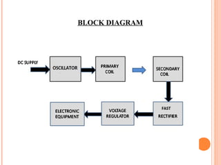
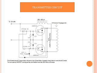
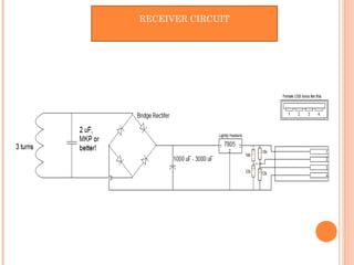
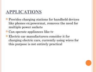
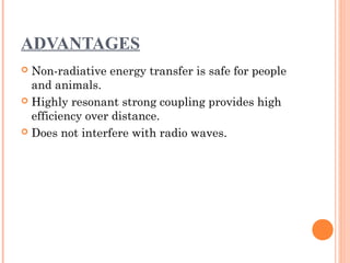
SUBMITTED BY :
MOHAMMAD AZHAR
Enrollment Number 2014-333-031
BTECH(ECE) 5th
SEM
SUBMITTED TO
Department of Computer Science & Engg.
JAMIA HAMDARD
WIRELESS POWER TRANSMISSION
(WIRELESS MOBILE CHARGER)
INTRODUCTION
Wireless power transfer can make electronic devices like cell
phones, household robots, mp3 players, laptop computers and
other portable electronics wire-free.
Resonant inductive coupling which is one of the various power
transmission techniques is demonstrated here.
ABSTRACT
 Many researchers have developed several techniques for
moving electricity over long distances without wires.
 Two objects having same resonating frequency and in
magnetic resonance tend to exchange energy, while
dissipating relatively little energy to the extraneous off-
resonant objects.
WORKING PRINCIPLE
This circuit mainly works on the principle of mutual inductance. Power
is transferred from transmitter to the receiver wirelessly based on the
principle of “inductive coupling”.
Inductance is the property of the conductor, in which the current flowing
in a conductor induces a voltage or electromotive force in it or in
another nearby conductor. There are two types inductance. 1) Self
inductance, 2)Mutual Inductance.
“Mutual inductance” is the phenomena in which, when a current
carrying conductor is placed near another conductor voltage is induced
in that conductor. This is because, as the current is flowing in the
conductor, a magnetic flux is induced in it. This induced magnetic flux
links with another conductor and this flux induces voltage in the second
conductor. Thus two conductors are said to be inductively coupled.
RESONANT INDUCTIVE COUPLING
 Inductive charging uses an electromagnetic field to
transfer energy between two objects.
 Greater distances can be achieved by using resonant
inductive coupling.
 Resonant inductive coupling or electrodynamic
induction is the near field wireless transmission between
two coils that are tuned to resonate at the same
frequency.
RESONANT INDUCTIVE COUPLING
 The capacitor and inductor forms the resonator. Charge
oscillates between inductor (as magnetic field) and
capacitor (as electric field.)
• This type of oscillation is called resonance if the
reactance's of the inductor and capacitor are equal.
COTINUE.............
•The capacitor and inductor forms the resonator.
Charge oscillates between inductor (as magnetic
field) and capacitor (as electric field.)
•This type of oscillation is called resonance if the
reactance's of the inductor and capacitor are equal.
BLOCK DIAGRAM
Hardware specification
•Transistor 1351
•Resistor
•Zener diode
•7805 voltage regulator
•Capacitor
•USB female port
TRANSMITTER CIRCUIT
RECEIVER CIRCUIT
APPLICATIONS
 Provides charging stations for handheld devices
like phones ex:powermat, removes the need for
multiple power sockets
 Can operate appliances like tv
 Electric car manufacturers consider it for
charging electric cars, currently using wires for
this purpose is not entirely practical
ADVANTAGES
 Non-radiative energy transfer is safe for people
and animals.
 Highly resonant strong coupling provides high
efficiency over distance.
 Does not interfere with radio waves.
LIMITATION OF THE CIRCUIT
 Power is somewhat wasted due to mutual
induction.
 It will work for very short distances only. If you
want to use it for long distances, then the
number of inductor turns should be high.
CONCLUSION
 Wireless power transfer is quickly becoming a
viable reality.
 This technology offers an extremely efficient
alternative to previous attempts at providing
wireless power.
 Future improvements in wireless technology offer
world changing implications.
RFERENCES
 Websites:
 www.google.co.in
 all about circuit-basic electronic equipment
function
 Wikipedia-www.wikipedia.org
 http://www.instructables.com/id/Wireless-Ipod-
Charger/?ALLSTEPS

Wireless power transmission

  • 1.
    SUBMITTED BY : MOHAMMADAZHAR Enrollment Number 2014-333-031 BTECH(ECE) 5th SEM SUBMITTED TO Department of Computer Science & Engg. JAMIA HAMDARD WIRELESS POWER TRANSMISSION (WIRELESS MOBILE CHARGER)
  • 2.
    INTRODUCTION Wireless power transfercan make electronic devices like cell phones, household robots, mp3 players, laptop computers and other portable electronics wire-free. Resonant inductive coupling which is one of the various power transmission techniques is demonstrated here.
  • 3.
    ABSTRACT  Many researchershave developed several techniques for moving electricity over long distances without wires.  Two objects having same resonating frequency and in magnetic resonance tend to exchange energy, while dissipating relatively little energy to the extraneous off- resonant objects.
  • 4.
    WORKING PRINCIPLE This circuitmainly works on the principle of mutual inductance. Power is transferred from transmitter to the receiver wirelessly based on the principle of “inductive coupling”. Inductance is the property of the conductor, in which the current flowing in a conductor induces a voltage or electromotive force in it or in another nearby conductor. There are two types inductance. 1) Self inductance, 2)Mutual Inductance. “Mutual inductance” is the phenomena in which, when a current carrying conductor is placed near another conductor voltage is induced in that conductor. This is because, as the current is flowing in the conductor, a magnetic flux is induced in it. This induced magnetic flux links with another conductor and this flux induces voltage in the second conductor. Thus two conductors are said to be inductively coupled.
  • 5.
    RESONANT INDUCTIVE COUPLING Inductive charging uses an electromagnetic field to transfer energy between two objects.  Greater distances can be achieved by using resonant inductive coupling.  Resonant inductive coupling or electrodynamic induction is the near field wireless transmission between two coils that are tuned to resonate at the same frequency.
  • 6.
    RESONANT INDUCTIVE COUPLING The capacitor and inductor forms the resonator. Charge oscillates between inductor (as magnetic field) and capacitor (as electric field.) • This type of oscillation is called resonance if the reactance's of the inductor and capacitor are equal.
  • 7.
    COTINUE............. •The capacitor andinductor forms the resonator. Charge oscillates between inductor (as magnetic field) and capacitor (as electric field.) •This type of oscillation is called resonance if the reactance's of the inductor and capacitor are equal.
  • 8.
  • 9.
    Hardware specification •Transistor 1351 •Resistor •Zenerdiode •7805 voltage regulator •Capacitor •USB female port
  • 10.
  • 11.
  • 12.
    APPLICATIONS  Provides chargingstations for handheld devices like phones ex:powermat, removes the need for multiple power sockets  Can operate appliances like tv  Electric car manufacturers consider it for charging electric cars, currently using wires for this purpose is not entirely practical
  • 13.
    ADVANTAGES  Non-radiative energytransfer is safe for people and animals.  Highly resonant strong coupling provides high efficiency over distance.  Does not interfere with radio waves.
  • 14.
    LIMITATION OF THECIRCUIT  Power is somewhat wasted due to mutual induction.  It will work for very short distances only. If you want to use it for long distances, then the number of inductor turns should be high.
  • 15.
    CONCLUSION  Wireless powertransfer is quickly becoming a viable reality.  This technology offers an extremely efficient alternative to previous attempts at providing wireless power.  Future improvements in wireless technology offer world changing implications.
  • 16.
    RFERENCES  Websites:  www.google.co.in all about circuit-basic electronic equipment function  Wikipedia-www.wikipedia.org  http://www.instructables.com/id/Wireless-Ipod- Charger/?ALLSTEPS