Downloaded 71 times
![4. REFERENCES
[1] Theoretical and experimental development of 10 and 35 GHz rectennas IEEE Transactions on
Microwave Theory and Techniques, vol. 40, no. 6, June 1992. Research supported by NASA and
U.S. Army.
[2] Pozar, David M. (1993). Microwave Engineering Addison–Wesley Publishing Company
[3]http://en.wikipedia.org/wiki/Rectenna
[4]http://computer.yourdictionary.com/magnetron
[5]http://www.engineeringexpert.net/EngineeringExpert-Witness-Blog/?tag=magnetron-tube
[6] Wireless Power Transmission – A Next Generation Power Transmission System,
International-al Journal of Computer Applications Volume 1 – No. 13
[7] Lander, Cyril W. (1993). "2. Rectifying Circuits". Power electronics (3rd ed. ed.). London:
McGraw-Hill. .](https://image.slidesharecdn.com/titlepage-140925095119-phpapp01/85/Seminar-Report-on-Wireless-Mobile-Charger-9-320.jpg)

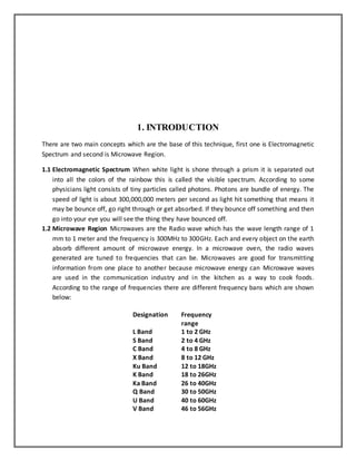
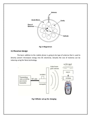
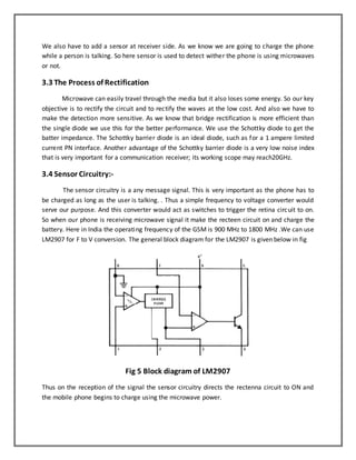
This document discusses wireless charging of mobile phones using microwaves. It begins with an introduction to electromagnetic spectrum and the microwave region. It then discusses how wireless power transmission works using magnetic induction. The key components of a wireless power transmission system are a microwave generator, transmitting antenna, and receiving antenna called a rectenna. The system design section explains the transmitter and receiver design, including the use of a magnetron as the microwave generator. It also discusses the rectification process and inclusion of a sensor circuitry to allow charging when the phone is in use.