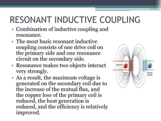
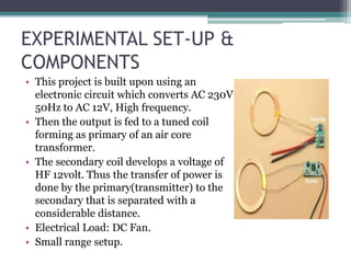
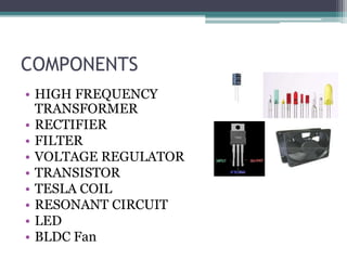
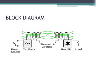
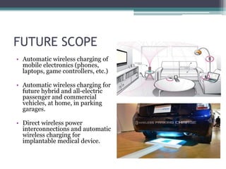
WIRELESS TRANSFER OF
ELECTRICITY
BY USING RESONANT
INDUCTIVE COUPLING PRESENTED BY:
SHUBHAM NAUTIYAL
SUMIT NAUTIYAL
BRANCH: EEE
UNDER THE SUPER VISION :
ARVIND SINGH BISHT
CONTENTS:
• INTRODUCTION
• HISTORY OF WIRELESS ELECTRICITY
• BASIC PRINCIPLE
• TYPES OF WITRICITY
• RESONANT INDUCTIVE COUPLING
• EXPERIMENTAL SET-UP & COMPONENTS
• BLOCK DIAGRAM
• ADVANTAGES AND DISADVANTAGES
• FUTURE SCOPE
• CONCLUSION
INTRODUCTION
• The Transfer of Electricity from one place to another without wires
is known as “WiTricity”.
• WiTricity technology is transferring electric energy or power over
distance.
• Because of Wi-tricity some of the devices won’t require batteries to
operate.
• Wireless energy transfer or wireless power is the transmission of
electrical energy from a power source to an electrical load without
interconnecting man-made conductors without wires, with the
basics of electricity and magnetism.
• In this project we are transferring the power by using Resonant
inductive coupling.
WHY WE NEED WITRICITY?
• Now-a-days due to rapid increase of
electronic goods like cell phones,
laptops, I-pods etc. Which rely on the
chemical storage of energy by the battery
& need to recharge frequently twice a
day.
• Leads to lot of E-waste.
• Precautions to be taken for electrician
while working otherwise he can get
shock.
• As they are becoming daily needs to
present generation, Wireless energy
transfer would be useful for many
applications as above and they need
midrange energy.
HISTORY OF WIRELESS ELECTRICITY
• Serbian scientist Nikola Tesla regarded
as Pioneer of Wireless Electricity.
• In 1894, Nikola Tesla lights
incandescent lamps wirelessly at the
laboratory in New York City by means
of "electro-dynamic induction" or
resonant inductive coupling.
• In 1899, Sir Nikola Tesla Proposed a
method of Wireless Power
Transmission.
• As it is in Radiative mode, most of the
Power was wasted and has less
efficiency. Able to light lamps over 25
miles away without using wires.
BASIC PRINCIPLE( faraday’s law )
• The principle which is use in these
circuit is faraday’s law of
electromagnetic induction.
• The first coil is attached to the
power source while the second coil
to the light bulb or load.
• When the power is switched on the
first coil converts the electricity into
magnetic field, which is oscillating
at a particular frequency i.e., AC
source.
• The second coil at the receiver end
converts the magnetic field into
electricity .
NEAR FIELD
• Valid only for few range (in meter).
• Uses Resonant inductive coupling between two
coils that are tuned to resonate at the same
frequency.
o MAGNETISM
▫ INDUCTIVE COUPLING
▫ RESONANT INDUCTIVE COUPLING
▫ CAPACITIVE COUPLING
▫ RESONANT CAPACITIVE COUPLING
▫ MAGNETO DYNAMIC COUPLING
FEATURES
• Highly Resonant Strong Coupling Provides High
Efficiency over Distance.
• Energy Transfer via Magnetic Field can
penetrate and wrap around obstacles.
• Non-Radiated Energy Transfer, hence is Safe for
People and Animals.
• Scalable Design enables solutions from
milliwatts to Kilowatts
RESONANT INDUCTIVE COUPLING
• Combination of inductive coupling and
resonance.
• The most basic resonant inductive
coupling consists of one drive coil on
the primary side and one resonance
circuit on the secondary side.
• Resonance makes two objects interact
very strongly.
• As a result, the maximum voltage is
generated on the secondary coil due to
the increase of the mutual flux, and
the copper loss of the primary coil is
reduced, the heat generation is
reduced, and the efficiency is relatively
improved.
EXPERIMENTAL SET-UP &
COMPONENTS
• This project is built upon using an
electronic circuit which converts AC 230V
50Hz to AC 12V, High frequency.
• Then the output is fed to a tuned coil
forming as primary of an air core
transformer.
• The secondary coil develops a voltage of
HF 12volt. Thus the transfer of power is
done by the primary(transmitter) to the
secondary that is separated with a
considerable distance.
• Electrical Load: DC Fan.
• Small range setup.
COMPONENTS
• HIGH FREQUENCY
TRANSFORMER
• RECTIFIER
• FILTER
• VOLTAGE REGULATOR
• TRANSISTOR
• TESLA COIL
• RESONANT CIRCUIT
• LED
• BLDC Fan
BLOCK DIAGRAM
ADVANTAGES
• Simple Design – The design is very simple in theory as well as
the physical implementation.
• Lower Frequency Operation – The operating frequency range
is in the kilohertz range.
• Low Cost - The entire system is designed with discrete
components that are readily available & of affordable price.
• Practical for Short Distance – The designed system is very
practical for short distance as long as the coupling coefficient
is optimized.
DISADVANTAGES
• High Power Loss – Due its air core design the flux
leakage is very high. This results in a high power loss and
low efficiency.
• Non-directional – The current design creates uniform
flux density and isn't directional.
• Inefficient for longer distances- The efficiency drops
exponentially with increase in distance.
FUTURE SCOPE
• Automatic wireless charging of
mobile electronics (phones,
laptops, game controllers, etc.)
• Automatic wireless charging for
future hybrid and all-electric
passenger and commercial
vehicles, at home, in parking
garages.
• Direct wireless power
interconnections and automatic
wireless charging for
implantable medical device.
THANK YOU

Shubham

  • 1.
    WIRELESS TRANSFER OF ELECTRICITY BYUSING RESONANT INDUCTIVE COUPLING PRESENTED BY: SHUBHAM NAUTIYAL SUMIT NAUTIYAL BRANCH: EEE UNDER THE SUPER VISION : ARVIND SINGH BISHT
  • 2.
    CONTENTS: • INTRODUCTION • HISTORYOF WIRELESS ELECTRICITY • BASIC PRINCIPLE • TYPES OF WITRICITY • RESONANT INDUCTIVE COUPLING • EXPERIMENTAL SET-UP & COMPONENTS • BLOCK DIAGRAM • ADVANTAGES AND DISADVANTAGES • FUTURE SCOPE • CONCLUSION
  • 3.
    INTRODUCTION • The Transferof Electricity from one place to another without wires is known as “WiTricity”. • WiTricity technology is transferring electric energy or power over distance. • Because of Wi-tricity some of the devices won’t require batteries to operate. • Wireless energy transfer or wireless power is the transmission of electrical energy from a power source to an electrical load without interconnecting man-made conductors without wires, with the basics of electricity and magnetism. • In this project we are transferring the power by using Resonant inductive coupling.
  • 4.
    WHY WE NEEDWITRICITY? • Now-a-days due to rapid increase of electronic goods like cell phones, laptops, I-pods etc. Which rely on the chemical storage of energy by the battery & need to recharge frequently twice a day. • Leads to lot of E-waste. • Precautions to be taken for electrician while working otherwise he can get shock. • As they are becoming daily needs to present generation, Wireless energy transfer would be useful for many applications as above and they need midrange energy.
  • 5.
    HISTORY OF WIRELESSELECTRICITY • Serbian scientist Nikola Tesla regarded as Pioneer of Wireless Electricity. • In 1894, Nikola Tesla lights incandescent lamps wirelessly at the laboratory in New York City by means of "electro-dynamic induction" or resonant inductive coupling. • In 1899, Sir Nikola Tesla Proposed a method of Wireless Power Transmission. • As it is in Radiative mode, most of the Power was wasted and has less efficiency. Able to light lamps over 25 miles away without using wires.
  • 6.
    BASIC PRINCIPLE( faraday’slaw ) • The principle which is use in these circuit is faraday’s law of electromagnetic induction. • The first coil is attached to the power source while the second coil to the light bulb or load. • When the power is switched on the first coil converts the electricity into magnetic field, which is oscillating at a particular frequency i.e., AC source. • The second coil at the receiver end converts the magnetic field into electricity .
  • 7.
    NEAR FIELD • Validonly for few range (in meter). • Uses Resonant inductive coupling between two coils that are tuned to resonate at the same frequency. o MAGNETISM ▫ INDUCTIVE COUPLING ▫ RESONANT INDUCTIVE COUPLING ▫ CAPACITIVE COUPLING ▫ RESONANT CAPACITIVE COUPLING ▫ MAGNETO DYNAMIC COUPLING
  • 8.
    FEATURES • Highly ResonantStrong Coupling Provides High Efficiency over Distance. • Energy Transfer via Magnetic Field can penetrate and wrap around obstacles. • Non-Radiated Energy Transfer, hence is Safe for People and Animals. • Scalable Design enables solutions from milliwatts to Kilowatts
  • 9.
    RESONANT INDUCTIVE COUPLING •Combination of inductive coupling and resonance. • The most basic resonant inductive coupling consists of one drive coil on the primary side and one resonance circuit on the secondary side. • Resonance makes two objects interact very strongly. • As a result, the maximum voltage is generated on the secondary coil due to the increase of the mutual flux, and the copper loss of the primary coil is reduced, the heat generation is reduced, and the efficiency is relatively improved.
  • 10.
    EXPERIMENTAL SET-UP & COMPONENTS •This project is built upon using an electronic circuit which converts AC 230V 50Hz to AC 12V, High frequency. • Then the output is fed to a tuned coil forming as primary of an air core transformer. • The secondary coil develops a voltage of HF 12volt. Thus the transfer of power is done by the primary(transmitter) to the secondary that is separated with a considerable distance. • Electrical Load: DC Fan. • Small range setup.
  • 11.
    COMPONENTS • HIGH FREQUENCY TRANSFORMER •RECTIFIER • FILTER • VOLTAGE REGULATOR • TRANSISTOR • TESLA COIL • RESONANT CIRCUIT • LED • BLDC Fan
  • 12.
  • 13.
    ADVANTAGES • Simple Design– The design is very simple in theory as well as the physical implementation. • Lower Frequency Operation – The operating frequency range is in the kilohertz range. • Low Cost - The entire system is designed with discrete components that are readily available & of affordable price. • Practical for Short Distance – The designed system is very practical for short distance as long as the coupling coefficient is optimized.
  • 14.
    DISADVANTAGES • High PowerLoss – Due its air core design the flux leakage is very high. This results in a high power loss and low efficiency. • Non-directional – The current design creates uniform flux density and isn't directional. • Inefficient for longer distances- The efficiency drops exponentially with increase in distance.
  • 15.
    FUTURE SCOPE • Automaticwireless charging of mobile electronics (phones, laptops, game controllers, etc.) • Automatic wireless charging for future hybrid and all-electric passenger and commercial vehicles, at home, in parking garages. • Direct wireless power interconnections and automatic wireless charging for implantable medical device.
  • 16.