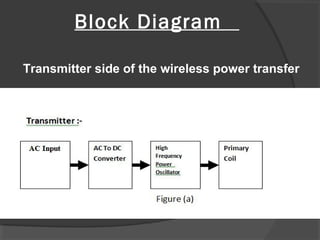
The End Of The Plug?
Submitted by.
Devendra Kumar
Girja Uike
Mani Kumar Dakshini
Tomeshwar Kumar Sahu
Guided by
Mr. Rahul Gupta
Department of electrical engineering
INTRODUCTION
 This is a special kind of transmitting of a power. In which
there is no need of any kind of communication wire to
connect the power supply. In this process where
electrical energy is transmitting from a power source to
an electrical load across an Air gap using induction coil.
From this circuit we can charge mobile or other devices
wirelessly in short range
Block Diagram
Transmitter side of the wireless power transfer
Receiver side of the wireless power transfer
Working Principle
 This circuit mainly work on the principle of
mutual induction. Power is transferred for
transmitter to receiver wirelessly based on the
inductive coupling.
Circuit Diagram
Bridge Rectifier
Circuit Diagram - Transmission Side
Oscillator
Circuit Diagram –Receiver
Side
Hardware Components description
 HIGH FREQUENCY TRANSFORMER
RECTIFIER
FILTER
VOLTAGE REGULATOR
TRANSISTOR
COIL
LED
1N4007
 RESISTOR
 CAPACITOR
HIGH FREQUENCY TRANSFORMER
2. Using In4007 as Bridge rectifier 3. Capacitors Filter(470µf)
4. 5v
Regulator
5. Relay
-:Advantage:-
 Low Cost.
 Low Power consumption.
 Easy to install.
 Effective in battery less device.
 Compact
 Short circuit avoided
 Eco Friendly
-:Limitations:-
 Low efficiency For long distance electricity
transfer
 Losses or energy due to winding or coil
-:Applications:-
 Medical devices.
 Battery less passive devices.
 Mobile phone charging.
 Contact less activation and detection.
 Running low current devices.
----Wireless power transfer is used in ----
-:Conclusion:-
 In conclusion that Resonant Inductive
coupling power transmission would be
extremely beneficial to society if it is were
implemented in home and home electronics.
From an environmental stand point this
technology could repulsed disposable battery
and Cords. Reducing dangerous chemical
and potential for poisoning communities
resonant inductive coupling has also health
benefiter
 Some people worry about health risks of
being exposed to the magnetic field coursed
by the resonant inductive coupling
 Many people see the huge benefit offer by
resonant coupling there are the medical
patent who can be help with this technology
 The limitation of the wireless power grandly
outweighed by the benefit and from an ethical
standpoint thus it is necessary further
developed wireless power technology to the
point large scale production
website
www.dkdynamics.com
Youtube links
www.youtube.com/HEnj6gxnNr8
-:Bibography:-
Reference Book
  Oscillator Circuit By David Mc Johns
 Fundamental of electronics by Williams
 The Tesla High frequency Oscillator (Tesla
Universe )
 J.Van Der Tang (High frequency oscillator
Design for integrated transceivers)
Thank you

wireless power transfer

  • 1.
    The End OfThe Plug? Submitted by. Devendra Kumar Girja Uike Mani Kumar Dakshini Tomeshwar Kumar Sahu Guided by Mr. Rahul Gupta Department of electrical engineering
  • 2.
    INTRODUCTION  This isa special kind of transmitting of a power. In which there is no need of any kind of communication wire to connect the power supply. In this process where electrical energy is transmitting from a power source to an electrical load across an Air gap using induction coil. From this circuit we can charge mobile or other devices wirelessly in short range
  • 3.
    Block Diagram Transmitter sideof the wireless power transfer
  • 4.
    Receiver side ofthe wireless power transfer
  • 5.
    Working Principle  Thiscircuit mainly work on the principle of mutual induction. Power is transferred for transmitter to receiver wirelessly based on the inductive coupling.
  • 6.
  • 7.
  • 8.
    Circuit Diagram -Transmission Side Oscillator
  • 9.
  • 10.
    Hardware Components description HIGH FREQUENCY TRANSFORMER RECTIFIER FILTER VOLTAGE REGULATOR TRANSISTOR COIL LED 1N4007  RESISTOR  CAPACITOR
  • 11.
  • 12.
    2. Using In4007as Bridge rectifier 3. Capacitors Filter(470µf) 4. 5v Regulator 5. Relay
  • 13.
    -:Advantage:-  Low Cost. Low Power consumption.  Easy to install.  Effective in battery less device.  Compact  Short circuit avoided  Eco Friendly
  • 14.
    -:Limitations:-  Low efficiencyFor long distance electricity transfer  Losses or energy due to winding or coil
  • 15.
    -:Applications:-  Medical devices. Battery less passive devices.  Mobile phone charging.  Contact less activation and detection.  Running low current devices. ----Wireless power transfer is used in ----
  • 16.
    -:Conclusion:-  In conclusionthat Resonant Inductive coupling power transmission would be extremely beneficial to society if it is were implemented in home and home electronics. From an environmental stand point this technology could repulsed disposable battery and Cords. Reducing dangerous chemical and potential for poisoning communities resonant inductive coupling has also health benefiter
  • 17.
     Some peopleworry about health risks of being exposed to the magnetic field coursed by the resonant inductive coupling  Many people see the huge benefit offer by resonant coupling there are the medical patent who can be help with this technology  The limitation of the wireless power grandly outweighed by the benefit and from an ethical standpoint thus it is necessary further developed wireless power technology to the point large scale production
  • 18.
  • 19.
    Reference Book   OscillatorCircuit By David Mc Johns  Fundamental of electronics by Williams  The Tesla High frequency Oscillator (Tesla Universe )  J.Van Der Tang (High frequency oscillator Design for integrated transceivers)
  • 20.