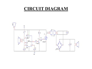
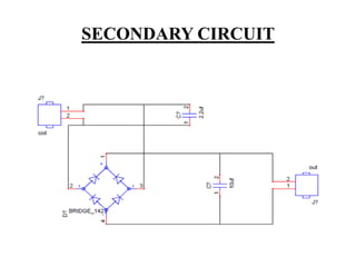
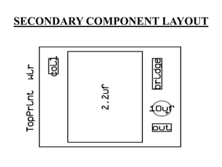
This document describes a project on wireless power transmission using resonant inductive coupling. It introduces various wireless power transmission techniques and focuses on resonant inductive coupling, which involves transferring energy between two coils that are tuned to resonate at the same frequency. The document includes circuit diagrams and layouts of the primary and secondary coils used to demonstrate resonant inductive coupling through an oscillator, resonant charging, and regulated output. It discusses applications for charging devices wirelessly and advantages like safety, efficiency and lack of interference.
2. INTRODUCTION
• Wireless power transfer can make electronic
devices like cell phones, household robots,
mp3 players, laptop computers and other
portable electronics wire-free.
• Resonant inductive coupling which is one of
the various power transmission techniques is
demonstrated here.
3. ABSTRACT
• Many researchers have developed several
techniques for moving electricity over long
distances without wires.
• Witricity is based upon coupled resonant objects.
• Two objects having same resonating frequency
and in magnetic resonance tend to exchange
energy, while dissipating relatively little energy to
the extraneous off-resonant objects.
4. RESONANT INDUCTIVE COUPLING
• Inductive charging uses an electromagnetic
field to transfer energy between two objects.
• Greater distances can be achieved by
using resonant inductive coupling.
• Resonant inductive
coupling or electrodynamic induction is
the near field wireless transmission between
two coils that are tuned to resonate at the
same frequency.
5. RESONANT INDUCTIVE COUPLING
• The capacitor and inductor forms the resonator. Charge
oscillates between inductor (as magnetic field) and
capacitor (as electric field.)
• This type of oscillation is called resonance if the
reactance's of the inductor and capacitor are equal.
6. RESONANT INDUCTIVE COUPLING
• Resonant transfer works by making a
coil ring with an oscillating current.
• This generates an oscillating magnetic field.
• Because the coil is highly resonant any energy
placed in the coil dies away relatively slowly over
very many cycles.
• But if a second coil is brought near it, the coil can
pick up most of the energy before it is lost, even if
it is some distance away.
8. BLOCK DIAGRAM
• Oscillator used is an astable multivibrator using
555timer which switches IRFP250 to produce
oscillations in the primary coil.
• Secondary coil kept at a distance resonates at the
same frequency and power transfer takes place.
• Signal received in the secondary is rectified and
regulated.
11. PRIMARY CIRCUIT
• Oscillator is an astable multivibrator using 555
timer a rectangular-wave generating circuit.
• A pot connected between the 6 and 7 terminals
of the timer is adjusted to tune the primary and
secondary coils at the same resonating frequency.
• The astable multivibrator causes an IRFP250
transistor to undergo switching to produce
oscillations of required strength.
• A primary coil made of 8 turns of a magnetic wire
is connected to IRFP250
18. APPLICATIONS
• Provides charging stations for handheld
devices like phones ex:powermat, removes
the need for multiple power sockets
• Can operate appliances like tv
• Electric car manufacturers consider it for
charging electric cars, currently using wires for
this purpose is not entirely practical
19. ADVANTAGES
• Non-radiative energy transfer is safe for
people and animals.
• Wastage of power is less.
• Highly resonant strong coupling provides high
efficiency over distance.
• Does not interfere with radio waves.
20. CONCLUSION
• Wireless power transfer is quickly becoming a
viable reality.
• This technology offers an extremely efficient
alternative to previous attempts at providing
wireless power.
• Future improvements in wireless technology
offer world changing implications.