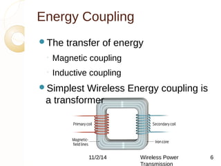
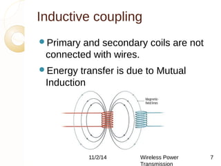
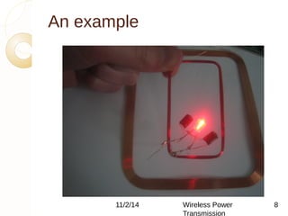
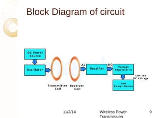
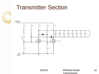
Wireless Charging Circuit 
Using Inductive Coupling 
BY:- 
Siddhant Singh
Overview 
What is wireless power 
transmission(WPT)? 
Why is WPT? 
History of WPT 
Types of WPT 
◦ Techniques to transfer energy wirelessly 
Advantages and disadvantages 
Applications 
Conclusion 
11/2/14 Wireless Power 
References 
Transmission 
2
What is WPT? 
The transmission of energy from one 
place to another without using wires 
Conventional energy transfer is using 
wires 
But, the wireless transmission is 
made possible by using various 
technologies 
11/2/14 Wireless Power 
Transmission 
3
Why WPT? 
Reliable 
Efficient 
Fast 
Low maintenance cost 
Can be used for short-range 
or long-range. 
11/2/14 Wireless Power 
Transmission 
4
History 
Nikola Tesla in late 1890s 
Pioneer of induction techniques 
His vision for “World Wireless System” 
The 187 feet tall tower to broadcast 
energy 
He managed to light 200 lamps from a 
distance of 40km 
11/2/14 Wireless Power 
Transmission 
5
Energy Coupling 
The transfer of energy 
◦ Magnetic coupling 
◦ Inductive coupling 
Simplest Wireless Energy coupling is 
a transformer 
11/2/14 Wireless Power 
Transmission 
6
Inductive coupling 
Primary and secondary coils are not 
connected with wires. 
Energy transfer is due to Mutual 
Induction 
11/2/14 Wireless Power 
Transmission 
7
An example 
11/2/14 Wireless Power 
Transmission 
8
Block Diagram of circuit 
11/2/14 Wireless Power 
Transmission 
9
Description of diagram 
11/2/14 Wireless Power 
Transmission 
10 
Works on the principle of inductive 
coupling 
Contains two sections-The 
Transmitter section and the Receiver 
section 
Transmitter coil converts the DC 
power to high frequency AC signal 
Receiver coil receives the power and 
convert it into AC signal
Transmitter Section 
11/2/14 Wireless Power 
Transmission 
11
Transmitter Section 
Description 
 DC power Source: It consists of a step 
down transformer that step downs the 
supply voltage to a desired level, and 
a rectifer circuit convert that AC voltage to 
DC signal 
Oscillator Circuit: A modified Royer 
Oscillator circuit is used in our project. With 
this circuit we can easily achieve a high 
oscillating current for the transmitter coil. 
Two N channel enhancement power 
MOSFET are 11/2/used 
14 Wireless Power 
Transmission 
Two chokes (L1 & L2) are used 
12
Transmitter Section (cont…) 
the transmitter coil L(inductor) 
 resistors R1,R2,R3 and R4 (works as 
a biasing network for Q1&Q2) 
 The operating frequency of the 
oscillator is determined by the 
resonance formula given below 
F = ½ × π × √ (LC) 
The equation for finding the 
inductance 11/2/of 14 a single Wireless layer Power 
air core 
coil is given below. 
Transmission 
13
Recevier Section 
11/2/14 Wireless Power 
Transmission 
14
Reciver Section Description 
consists of receiver coil 
 rectifier circuit and a voltage 
regulator IC. 
The rectifier circuit in the receiver 
section converts this AC voltage in to 
DC 
Voltage control IC helps to provide a 
constant limited regulated output 
voltage to the load for charging 
11/2/14 Wireless Power 
Transmission 
15
Recevier section (cont….) 
 LM 7805 voltage regulator IC is used 
 The IC gives a regulated 5V as its 
output 
It don’t allow more than 5V to the 
output. 
Copper wire having diameter of 8cm 
is used. 
equation for finding the inductance of 
a single layer 11/2/14 air core Wireless coil is Power 
given 
below 
Transmission 
16
Advantages of near-field 
techniques 
No wires 
No e-waste 
Need for battery 
is eliminated 
Efficient energy 
transfer using RIC 
Harmless, if field 
strengths under 
safety levels 
11/2/14 Wireless Power 
Transmission 
Maintenance cost 
17
Disadvantages 
Distance constraint 
Field strengths have to be under 
safety levels 
Initial cost is high 
In RIC, tuning is difficult 
High frequency signals must be the 
supply 
Air ionization technique is not feasible 
11/2/14 Wireless Power 
Transmission 
18
Applications 
Near-field energy transfer 
◦ Electric automobile charging 
 Static and moving 
◦ Consumer electronics 
◦ Industrial purposes 
 Harsh environment 
Far-field energy transfer 
◦ Solar Power Satellites 
◦ Energy to remote areas 
◦ Can broadcast energy 11/2/14 globWalilryel e(sins Pfuowtuerr e) 
Transmission 
19
Conclusion 
Transmission without wires- a reality 
Efficient 
Low maintenance cost. But, high initial cost 
Better than conventional wired transfer 
Energy crisis can be decreased 
Low loss 
In near future, world will be completely 
wireless 
11/2/14 Wireless Power 
Transmission 
20
References 
S. Sheik Mohammed, K. Ramasamy, 
T. Shanmuganantham,” Wireless 
power transmission – a next 
generation power transmission 
system”, International Journal of 
Computer Applications (0975 – 8887) 
(Volume 1 – No. 13) 
Peter Vaessen,” Wireless Power 
Transmission”, Leonardo Energy, 
September 2009 
11/2/14 Wireless Power 
C.C. Leung, T.P. Chan, Transmission 
K.C. Lit, K.W. 
21
THANK YOU! 
11/2/14 Wireless Power 
Transmission 
22

Wireless mobile charging by Inductive Coupling.

  • 1.
    Wireless Charging Circuit Using Inductive Coupling BY:- Siddhant Singh
  • 2.
    Overview What iswireless power transmission(WPT)? Why is WPT? History of WPT Types of WPT ◦ Techniques to transfer energy wirelessly Advantages and disadvantages Applications Conclusion 11/2/14 Wireless Power References Transmission 2
  • 3.
    What is WPT? The transmission of energy from one place to another without using wires Conventional energy transfer is using wires But, the wireless transmission is made possible by using various technologies 11/2/14 Wireless Power Transmission 3
  • 4.
    Why WPT? Reliable Efficient Fast Low maintenance cost Can be used for short-range or long-range. 11/2/14 Wireless Power Transmission 4
  • 5.
    History Nikola Teslain late 1890s Pioneer of induction techniques His vision for “World Wireless System” The 187 feet tall tower to broadcast energy He managed to light 200 lamps from a distance of 40km 11/2/14 Wireless Power Transmission 5
  • 6.
    Energy Coupling Thetransfer of energy ◦ Magnetic coupling ◦ Inductive coupling Simplest Wireless Energy coupling is a transformer 11/2/14 Wireless Power Transmission 6
  • 7.
    Inductive coupling Primaryand secondary coils are not connected with wires. Energy transfer is due to Mutual Induction 11/2/14 Wireless Power Transmission 7
  • 8.
    An example 11/2/14Wireless Power Transmission 8
  • 9.
    Block Diagram ofcircuit 11/2/14 Wireless Power Transmission 9
  • 10.
    Description of diagram 11/2/14 Wireless Power Transmission 10 Works on the principle of inductive coupling Contains two sections-The Transmitter section and the Receiver section Transmitter coil converts the DC power to high frequency AC signal Receiver coil receives the power and convert it into AC signal
  • 11.
    Transmitter Section 11/2/14Wireless Power Transmission 11
  • 12.
    Transmitter Section Description  DC power Source: It consists of a step down transformer that step downs the supply voltage to a desired level, and a rectifer circuit convert that AC voltage to DC signal Oscillator Circuit: A modified Royer Oscillator circuit is used in our project. With this circuit we can easily achieve a high oscillating current for the transmitter coil. Two N channel enhancement power MOSFET are 11/2/used 14 Wireless Power Transmission Two chokes (L1 & L2) are used 12
  • 13.
    Transmitter Section (cont…) the transmitter coil L(inductor)  resistors R1,R2,R3 and R4 (works as a biasing network for Q1&Q2)  The operating frequency of the oscillator is determined by the resonance formula given below F = ½ × π × √ (LC) The equation for finding the inductance 11/2/of 14 a single Wireless layer Power air core coil is given below. Transmission 13
  • 14.
    Recevier Section 11/2/14Wireless Power Transmission 14
  • 15.
    Reciver Section Description consists of receiver coil  rectifier circuit and a voltage regulator IC. The rectifier circuit in the receiver section converts this AC voltage in to DC Voltage control IC helps to provide a constant limited regulated output voltage to the load for charging 11/2/14 Wireless Power Transmission 15
  • 16.
    Recevier section (cont….)  LM 7805 voltage regulator IC is used  The IC gives a regulated 5V as its output It don’t allow more than 5V to the output. Copper wire having diameter of 8cm is used. equation for finding the inductance of a single layer 11/2/14 air core Wireless coil is Power given below Transmission 16
  • 17.
    Advantages of near-field techniques No wires No e-waste Need for battery is eliminated Efficient energy transfer using RIC Harmless, if field strengths under safety levels 11/2/14 Wireless Power Transmission Maintenance cost 17
  • 18.
    Disadvantages Distance constraint Field strengths have to be under safety levels Initial cost is high In RIC, tuning is difficult High frequency signals must be the supply Air ionization technique is not feasible 11/2/14 Wireless Power Transmission 18
  • 19.
    Applications Near-field energytransfer ◦ Electric automobile charging  Static and moving ◦ Consumer electronics ◦ Industrial purposes  Harsh environment Far-field energy transfer ◦ Solar Power Satellites ◦ Energy to remote areas ◦ Can broadcast energy 11/2/14 globWalilryel e(sins Pfuowtuerr e) Transmission 19
  • 20.
    Conclusion Transmission withoutwires- a reality Efficient Low maintenance cost. But, high initial cost Better than conventional wired transfer Energy crisis can be decreased Low loss In near future, world will be completely wireless 11/2/14 Wireless Power Transmission 20
  • 21.
    References S. SheikMohammed, K. Ramasamy, T. Shanmuganantham,” Wireless power transmission – a next generation power transmission system”, International Journal of Computer Applications (0975 – 8887) (Volume 1 – No. 13) Peter Vaessen,” Wireless Power Transmission”, Leonardo Energy, September 2009 11/2/14 Wireless Power C.C. Leung, T.P. Chan, Transmission K.C. Lit, K.W. 21
  • 22.
    THANK YOU! 11/2/14Wireless Power Transmission 22