Sachpazis: Wind loading to EN 1991 1-4- for a hipped roof example
•
6 likes•7,238 views

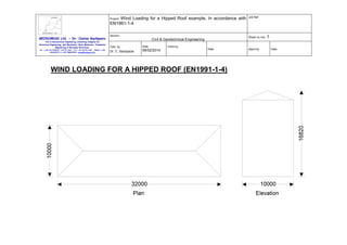
Wind Loading for a Hipped Roof example, In accordance with EN1991-1-4
![Wind Loading for a Hipped Roof example, In accordance with
EN1991-1-4
Job Ref.
Section
Sheet no./rev. 1
Project:
GEODOMISI Ltd. - Dr. Costas Sachpazis
Civil & Geotechnical Engineering Consulting Company for
Structural Engineering, Soil Mechanics, Rock Mechanics, Foundation
Engineering & Retaining Structures.
Tel.: (+30) 210 5238127, 210 5711263 - Fax.:+30 210 5711461 - Mobile: (+30)
6936425722 & (+44) 7585939944, costas@sachpazis.info
Civil & Geotechnical Engineering
Calc. by
Date
Dr. C. Sachpazis
08/02/2014
Chk'd by
Date
Building data
Type of roof;
Hipped
Length of building;
L = 32000 mm
Width of building;
W = 10000 mm
Height to eaves;
H = 15000 mm
Pitch of main slope;
α0 = 20.0 deg
Pitch of gable slope;
α90 = 20.0 deg
Total height;
h = 16820 mm
Basic values
Fundamental basic wind velocity;
vb,0 = 21.8 m/s
Season factor;
cseason = 1.00
Direction factor;
cdir = 1.00
Shape parameter K;
K = 0.2
Exponent n;
n = 0.5
Probability factor;
cprob = [(1 - K × ln(-ln(1-p)))/(1 - K × ln(-ln(0.98)))] = 1.00
n
Basic wind velocity (Exp. 4.1);
vb = cdir × cseason × vb,0 × cprob = 21.8 m/s
Reference mean velocity pressure;
qb = 0.5 × ρ × vb = 0.298 kN/m
2
Orography
Orography factor not significant;
co = 1.0
Terrain category;
Average height of surrounding buildings;
IV
have = 15000 mm
Distance to nearest building;
xdis = 30000 mm
2
App'd by
Date](data:image/gif;base64,R0lGODlhAQABAIAAAAAAAP///yH5BAEAAAAALAAAAAABAAEAAAIBRAA7)
Recommended
More Related Content
What's hot
What's hot (20)
Viewers also liked
Viewers also liked (20)
Similar to Sachpazis: Wind loading to EN 1991 1-4- for a hipped roof example
Similar to Sachpazis: Wind loading to EN 1991 1-4- for a hipped roof example (20)
More from Dr.Costas Sachpazis
More from Dr.Costas Sachpazis (20)
Recently uploaded
Recently uploaded (20)
Sachpazis: Wind loading to EN 1991 1-4- for a hipped roof example
- 1. Wind Loading for a Hipped Roof example, In accordance with EN1991-1-4 Job Ref. Section Sheet no./rev. 1 Project: GEODOMISI Ltd. - Dr. Costas Sachpazis Civil & Geotechnical Engineering Consulting Company for Structural Engineering, Soil Mechanics, Rock Mechanics, Foundation Engineering & Retaining Structures. Tel.: (+30) 210 5238127, 210 5711263 - Fax.:+30 210 5711461 - Mobile: (+30) 6936425722 & (+44) 7585939944, costas@sachpazis.info Civil & Geotechnical Engineering Calc. by Date Dr. C. Sachpazis 08/02/2014 Chk'd by Date WIND LOADING FOR A HIPPED ROOF (EN1991-1-4) App'd by Date
- 2. Wind Loading for a Hipped Roof example, In accordance with EN1991-1-4 Job Ref. Section Sheet no./rev. 1 Project: GEODOMISI Ltd. - Dr. Costas Sachpazis Civil & Geotechnical Engineering Consulting Company for Structural Engineering, Soil Mechanics, Rock Mechanics, Foundation Engineering & Retaining Structures. Tel.: (+30) 210 5238127, 210 5711263 - Fax.:+30 210 5711461 - Mobile: (+30) 6936425722 & (+44) 7585939944, costas@sachpazis.info Civil & Geotechnical Engineering Calc. by Date Dr. C. Sachpazis 08/02/2014 Chk'd by Date Building data Type of roof; Hipped Length of building; L = 32000 mm Width of building; W = 10000 mm Height to eaves; H = 15000 mm Pitch of main slope; α0 = 20.0 deg Pitch of gable slope; α90 = 20.0 deg Total height; h = 16820 mm Basic values Fundamental basic wind velocity; vb,0 = 21.8 m/s Season factor; cseason = 1.00 Direction factor; cdir = 1.00 Shape parameter K; K = 0.2 Exponent n; n = 0.5 Probability factor; cprob = [(1 - K × ln(-ln(1-p)))/(1 - K × ln(-ln(0.98)))] = 1.00 n Basic wind velocity (Exp. 4.1); vb = cdir × cseason × vb,0 × cprob = 21.8 m/s Reference mean velocity pressure; qb = 0.5 × ρ × vb = 0.298 kN/m 2 Orography Orography factor not significant; co = 1.0 Terrain category; Average height of surrounding buildings; IV have = 15000 mm Distance to nearest building; xdis = 30000 mm 2 App'd by Date
- 3. Wind Loading for a Hipped Roof example, In accordance with EN1991-1-4 Job Ref. Section Sheet no./rev. 1 Project: GEODOMISI Ltd. - Dr. Costas Sachpazis Civil & Geotechnical Engineering Consulting Company for Structural Engineering, Soil Mechanics, Rock Mechanics, Foundation Engineering & Retaining Structures. Tel.: (+30) 210 5238127, 210 5711263 - Fax.:+30 210 5711461 - Mobile: (+30) 6936425722 & (+44) 7585939944, costas@sachpazis.info Civil & Geotechnical Engineering Calc. by Date Dr. C. Sachpazis 08/02/2014 Chk'd by Date App'd by Date The velocity pressure for the windward face of the building with a 0 degree wind is to be considered as 1 part as the height h is less than b (cl.7.2.2) The velocity pressure for the windward face of the building with a 90 degree wind is to be considered as 2 parts as the height h is greater than b but less than 2b (cl.7.2.2) Peak velocity pressure - windward wall - Wind 0 deg Reference height (at which q is sought); z = 15000mm Displacement height (Annex A.2); hdis = min(0.8 × have, 0.6 × z) = 9000 mm Roughness length (Table 4.1); z0 = 1000 mm Roughness length (Category II); z0,II = 50 mm Minimum height (Table 4.1); zmin = 10000 mm Maximum height; zmax = 200000 mm Terrain factor; kr = 0.19 × (z0 / z0,II) Roughness factor; cr = kr × ln(zmin / z0) = 0.54 Mean wind; vm = cr × co × vb = 11.8 m/s 0.07 = 0.23 Turbulence factor; kI = 1.0 Turbulence intensity; Iv = kI / (co × ln(zmin / z0)) = 0.434 Peak velocity pressure; qp = (1 + 7 × Iv) × 0.5 × ρ × vm = 0.35 kN/m 2 Structural factor Building type; Structural factor (Annex D); Concrete csCd = 0.79 Peak velocity pressure - windward wall (lower part) - Wind 90 deg Reference height (at which q is sought); z = 10000mm Displacement height (Annex A.2); hdis = min(0.8 × have, 0.6 × z) = 6000 mm Terrain factor; kr = 0.19 × (z0 / z0,II) Roughness factor; cr = kr × ln(zmin / z0) = 0.54 0.07 = 0.23 2
- 4. Wind Loading for a Hipped Roof example, In accordance with EN1991-1-4 Job Ref. Section Sheet no./rev. 1 Project: GEODOMISI Ltd. - Dr. Costas Sachpazis Civil & Geotechnical Engineering Consulting Company for Structural Engineering, Soil Mechanics, Rock Mechanics, Foundation Engineering & Retaining Structures. Tel.: (+30) 210 5238127, 210 5711263 - Fax.:+30 210 5711461 - Mobile: (+30) 6936425722 & (+44) 7585939944, costas@sachpazis.info Civil & Geotechnical Engineering Calc. by Date Dr. C. Sachpazis 08/02/2014 Chk'd by Date Mean wind; vm = cr × co × vb = 11.8 m/s Turbulence factor; kI = 1.0 Turbulence intensity; Iv = kI / (co × ln(zmin / z0)) = 0.434 Peak velocity pressure; qp = (1 + 7 × Iv) × 0.5 × ρ × vm = 0.35 kN/m 2 2 Peak velocity pressure - windward wall (upper part) - Wind 90 deg Reference height (at which q is sought); z = 15000mm Displacement height (Annex A.2); hdis = min(0.8 × have, 0.6 × z) = 9000 mm Terrain factor; kr = 0.19 × (z0 / z0,II) Roughness factor; cr = kr × ln(zmin / z0) = 0.54 0.07 = 0.23 Mean wind; vm = cr × co × vb = 11.8 m/s Turbulence factor; kI = 1.0 Turbulence intensity; Iv = kI / (co × ln(zmin / z0)) = 0.434 Peak velocity pressure; qp = (1 + 7 × Iv) × 0.5 × ρ × vm = 0.35 kN/m 2 2 Peak velocity pressure - roof Reference height (at which q is sought); z = 16820mm Displacement height (Annex A.2); hdis = min(0.8 × have, 0.6 × z) = 10092 mm Terrain factor; kr = 0.19 × (z0 / z0,II) Roughness factor; cr = kr × ln(zmin / z0) = 0.54 0.07 = 0.23 Mean wind; vm = cr × co × vb = 11.8 m/s Turbulence factor; kI = 1.0 Turbulence intensity; Iv = kI / (co × ln(zmin / z0)) = 0.434 Peak velocity pressure; qp = (1 + 7 × Iv) × 0.5 × ρ × vm = 0.35 kN/m 2 Peak velocity pressure for internal pressure Peak velocity pressure – internal (as roof press.); qp,i = 0.35 kN/m 2 2 App'd by Date
- 5. Wind Loading for a Hipped Roof example, In accordance with EN1991-1-4 Job Ref. Section Sheet no./rev. 1 Project: GEODOMISI Ltd. - Dr. Costas Sachpazis Civil & Geotechnical Engineering Consulting Company for Structural Engineering, Soil Mechanics, Rock Mechanics, Foundation Engineering & Retaining Structures. Tel.: (+30) 210 5238127, 210 5711263 - Fax.:+30 210 5711461 - Mobile: (+30) 6936425722 & (+44) 7585939944, costas@sachpazis.info Civil & Geotechnical Engineering Calc. by Date Dr. C. Sachpazis 08/02/2014 Chk'd by Date App'd by Pressures and forces Net pressure; p = csCd × qp × cpe - qp,i × cpi; Net force; Fw = pw × Aref; Roof load case 1 - Wind 0, cpi -0.30, - cpe Zone Ext pressure coefficient cpe Peak velocity pressure 2 qp, (kN/m ) Net pressure 2 p (kN/m ) Area 2 Aref (m ) Net force Fw (kN) F (-ve) -0.77 0.35 -0.11 43.59 -4.67 G (-ve) -0.70 0.35 -0.09 54.49 -4.83 H (-ve) -0.27 0.35 0.03 45.59 1.43 I (-ve) -0.47 0.35 -0.02 80.32 -1.93 J (-ve) -0.90 0.35 -0.14 23.16 -3.33 K (-ve) -0.97 0.35 -0.16 40.18 -6.52 L (-ve) -1.40 0.35 -0.28 28.61 -8.07 M (-ve) -0.67 0.35 -0.08 24.60 -1.95 Total vertical net force; Fw,v = -28.08 kN Total horizontal net force; Fw,h = 1.27 kN Walls load case 1 - Wind 0, cpi -0.30, - cpe Zone Ext pressure coefficient cpe Peak velocity pressure 2 qp, (kN/m ) Net pressure 2 p (kN/m ) Area 2 Aref (m ) Net force Fw (kN) A -1.20 0.35 -0.23 96.00 -21.71 B -0.80 0.35 -0.12 54.00 -6.25 Date
- 6. Wind Loading for a Hipped Roof example, In accordance with EN1991-1-4 Job Ref. Section Sheet no./rev. 1 Project: GEODOMISI Ltd. - Dr. Costas Sachpazis Civil & Geotechnical Engineering Consulting Company for Structural Engineering, Soil Mechanics, Rock Mechanics, Foundation Engineering & Retaining Structures. Tel.: (+30) 210 5238127, 210 5711263 - Fax.:+30 210 5711461 - Mobile: (+30) 6936425722 & (+44) 7585939944, costas@sachpazis.info Civil & Geotechnical Engineering Calc. by Date Dr. C. Sachpazis 08/02/2014 Chk'd by Date App'd by D 0.80 0.35 0.33 480.00 156.42 E -0.53 0.35 -0.04 480.00 -20.32 Overall loading Equiv leeward net force for overall section; Fl = Fw,wE = -20.3 kN Net windward force for overall section; Fw = Fw,wD = 156.4 kN Lack of correlation (cl.7.2.2(3) – Note); fcorr = 0.88; as h/W is 1.682 Overall loading overall section; Fw,D = fcorr × (Fw - Fl) + Fw,h = 156.0 kN Roof load case 2 - Wind 90, cpi -0.30, - cpe Zone Ext pressure coefficient cpe Peak velocity pressure 2 qp, (kN/m ) Net pressure 2 p (kN/m ) Area 2 Aref (m ) Net force Fw (kN) F (-ve) -0.77 0.35 -0.12 4.26 -0.53 G (-ve) -0.70 0.35 -0.10 5.32 -0.56 H (-ve) -0.27 0.35 0.03 17.03 0.43 I (-ve) -0.47 0.35 -0.03 17.03 -0.59 J (-ve) -0.90 0.35 -0.16 9.58 -1.58 L (-ve) -1.40 0.35 -0.31 10.64 -3.35 M (-ve) -0.67 0.35 -0.09 17.03 -1.61 N (-ve) -0.27 0.35 0.03 259.66 6.53 Total vertical net force; Fw,v = -1.19 kN Total horizontal net force; Fw,h = 0.52 kN Walls load case 2 - Wind 90, cpi -0.30, - cpe Date
- 7. Wind Loading for a Hipped Roof example, In accordance with EN1991-1-4 Job Ref. Section Sheet no./rev. 1 Project: GEODOMISI Ltd. - Dr. Costas Sachpazis Civil & Geotechnical Engineering Consulting Company for Structural Engineering, Soil Mechanics, Rock Mechanics, Foundation Engineering & Retaining Structures. Civil & Geotechnical Engineering Calc. by Date Dr. C. Sachpazis 08/02/2014 Zone Ext pressure coefficient cpe Peak velocity pressure 2 qp, (kN/m ) Net pressure 2 p (kN/m ) Area 2 Aref (m ) Net force Fw (kN) A -1.20 0.35 -0.25 30.00 -7.64 B -0.80 0.35 -0.13 120.00 -16.17 C -0.50 0.35 -0.04 330.00 -14.78 Db 0.74 0.35 0.33 100.00 32.99 Du 0.74 0.35 0.34 50.00 16.76 E -0.37 0.35 -0.01 150.00 -1.03 Tel.: (+30) 210 5238127, 210 5711263 - Fax.:+30 210 5711461 - Mobile: (+30) 6936425722 & (+44) 7585939944, costas@sachpazis.info Chk'd by Date Overall loading Equiv leeward net force for upper section; Fl = Fw,wE / Aref,wE × Aref,wu = -0.3 kN Net windward force for upper section; Fw = Fw,wu = 16.8 kN Lack of correlation (cl.7.2.2(3) – Note); fcorr = 0.85; as h/L is 0.526 Overall loading upper section; Fw,u = fcorr × (Fw - Fl) + Fw,h = 15.1 kN Equiv leeward net force for bottom section; Fl = Fw,wE / Aref,wE × Aref,wb = -0.7 kN Net windward force for bottom section; Fw = Fw,wb = 33.0 kN Lack of correlation (cl.7.2.2(3) – Note); fcorr = 0.85; as h/L is 0.526 Overall loading bottom section; Fw,b = fcorr × (Fw - Fl) = 28.6 kN App'd by Date
- 8. Wind Loading for a Hipped Roof example, In accordance with EN1991-1-4 Job Ref. Section Sheet no./rev. 1 Project: GEODOMISI Ltd. - Dr. Costas Sachpazis Civil & Geotechnical Engineering Consulting Company for Structural Engineering, Soil Mechanics, Rock Mechanics, Foundation Engineering & Retaining Structures. Tel.: (+30) 210 5238127, 210 5711263 - Fax.:+30 210 5711461 - Mobile: (+30) 6936425722 & (+44) 7585939944, costas@sachpazis.info Civil & Geotechnical Engineering Calc. by Date Dr. C. Sachpazis 08/02/2014 Chk'd by Date App'd by Date
- 9. Wind Loading for a Hipped Roof example, In accordance with EN1991-1-4 Job Ref. Section Sheet no./rev. 1 Project: GEODOMISI Ltd. - Dr. Costas Sachpazis Civil & Geotechnical Engineering Consulting Company for Structural Engineering, Soil Mechanics, Rock Mechanics, Foundation Engineering & Retaining Structures. Tel.: (+30) 210 5238127, 210 5711263 - Fax.:+30 210 5711461 - Mobile: (+30) 6936425722 & (+44) 7585939944, costas@sachpazis.info Civil & Geotechnical Engineering Calc. by Date Dr. C. Sachpazis 08/02/2014 Chk'd by Date App'd by Date
- 10. Wind Loading for a Hipped Roof example, In accordance with EN1991-1-4 Job Ref. Section Sheet no./rev. 1 Project: GEODOMISI Ltd. - Dr. Costas Sachpazis Civil & Geotechnical Engineering Consulting Company for Structural Engineering, Soil Mechanics, Rock Mechanics, Foundation Engineering & Retaining Structures. Date Dr. C. Sachpazis 08/02/2014 Chk'd by Date App'd by Date L J Calc. by L Tel.: (+30) 210 5238127, 210 5711263 - Fax.:+30 210 5711461 - Mobile: (+30) 6936425722 & (+44) 7585939944, costas@sachpazis.info Civil & Geotechnical Engineering J