Sachpazis Foundation Pad with Two Columns Analysis & Design According to EC2 1992-1-1-2004 & EC7 with NA=CEN
•
2 likes•770 views

This document provides analysis and design calculations for the foundation of a pad supporting two columns according to Eurocode standards. It includes details of the foundation geometry and applied loads, as well as soil properties and calculations of bearing capacity, settlement, sliding resistance, and overturning to check if code requirements are satisfied. Diagrams and input parameters are provided over 13 pages of calculations and output.
![GEODOMISI Ltd. - Dr. Costas Sachpazis
Civil & Geotechnical Engineering Consulting Company for
Structural Engineering, Soil Mechanics, Rock Mechanics,
Foundation Engineering & Retaining Structures.
Tel.: (+30) 210 5238127, 210 5711263 - Fax.:+30 210 5711461 -
Mobile: (+30) 6936425722 & (+44) 7585939944,
www.geodomisi.com - costas@sachpazis.info
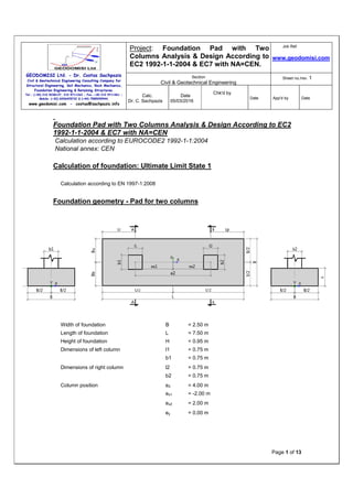
Project: Foundation Pad with Two
Columns Analysis & Design According to
EC2 1992-1-1-2004 & EC7 with NA=CEN.
Job Ref.
www.geodomisi.com
Section
Civil & Geotechnical Engineering
Sheet no./rev. 1
Calc.
Dr. C. Sachpazis
Date
05/03/2016
Chk'd by
Date App'd by Date
Page 2 of 13
Soil input
Nr Name Z
[m]
H
[m]
γsoil
[kN/m
3
]
γs
[kN/m
3
]
γd
[kN/m
3
]
φ'
[deg]
C'
[kPa]
Cu
[kPa]
MOi
[kPa]
Mi
[kPa]
1 poorly
graded
gravels
-4.90 4.90 20.50 26.00 20.50 0.70 0.00 0.00 19200.00 19200.00
2 clayey sands -11.00 6.00 11.09 26.80 20.00 0.40 0.00 74.00 36000.00 36000.00
3 silty clays -14.50 3.50 7.12 26.80 17.00 0.44 25.00 86.00 24000.00 24000.00
4 sand - silt
mixtures
-15.50 1.00 12.18 26.50 21.00 0.47 35.00 50.00 22800.00 22800.00
Foundation formation level zFL = -2.50 m
Ground water level zWL = -5.50 m
Foundation cast-in-situ
Depth of unplanned excavation hsoil = 1.00 m
Bearing pressure check Critical ULS1 qmax / qult = 76% Pass
Sliding check Critical ULS1 Hxd / Rxres = 11% Pass
Sliding check Critical ULS1 Hyd / Ryres = 0% Pass
Uplift check (UPL) Critical SLS1 Vdst,d / Gstb,d = 0% Pass
Loads
Design load combinations:
Name Limit
state
VA
[kN]
VB
[kN]
HxA
[kN]
HxB
[kN]
HyA
[kN]
HyB
[kN]
MxA
[kNm]
MxB
[kNm]
MyA
[kNm]
MyB
[kNm]
q
[kPa]
ULS1 ULS 1150.0
0
1035.0
0
250.00 75.00 25.00 -35.00 185.00 -105.00 245.00 155.00 15.00
Bearing pressure check
Critical ULS1 qmax / qult = 76% Pass](data:image/gif;base64,R0lGODlhAQABAIAAAAAAAP///yH5BAEAAAAALAAAAAABAAEAAAIBRAA7)
Recommended
More Related Content
What's hot
What's hot (20)
Viewers also liked
Viewers also liked (18)
Similar to Sachpazis Foundation Pad with Two Columns Analysis & Design According to EC2 1992-1-1-2004 & EC7 with NA=CEN
Similar to Sachpazis Foundation Pad with Two Columns Analysis & Design According to EC2 1992-1-1-2004 & EC7 with NA=CEN (16)
More from Dr.Costas Sachpazis
More from Dr.Costas Sachpazis (20)
Recently uploaded
Recently uploaded (20)
Sachpazis Foundation Pad with Two Columns Analysis & Design According to EC2 1992-1-1-2004 & EC7 with NA=CEN
- 1. GEODOMISI Ltd. - Dr. Costas Sachpazis Civil & Geotechnical Engineering Consulting Company for Structural Engineering, Soil Mechanics, Rock Mechanics, Foundation Engineering & Retaining Structures. Tel.: (+30) 210 5238127, 210 5711263 - Fax.:+30 210 5711461 - Mobile: (+30) 6936425722 & (+44) 7585939944, www.geodomisi.com - costas@sachpazis.info Project: Foundation Pad with Two Columns Analysis & Design According to EC2 1992-1-1-2004 & EC7 with NA=CEN. Job Ref. www.geodomisi.com Section Civil & Geotechnical Engineering Sheet no./rev. 1 Calc. Dr. C. Sachpazis Date 05/03/2016 Chk'd by Date App'd by Date Page 1 of 13 Foundation Pad with Two Columns Analysis & Design According to EC2 1992-1-1-2004 & EC7 with NA=CEN Calculation according to EUROCODE2 1992-1-1:2004 National annex: CEN Calculation of foundation: Ultimate Limit State 1 Calculation according to EN 1997-1:2008 Foundation geometry - Pad for two columns Width of foundation B = 2.50 m Length of foundation L = 7.50 m Height of foundation H = 0.95 m Dimensions of left column l1 = 0.75 m b1 = 0.75 m Dimensions of right column l2 = 0.75 m b2 = 0.75 m Column position e2 = 4.00 m ex1 = -2.00 m ex2 = 2.00 m ey = 0.00 m
- 2. GEODOMISI Ltd. - Dr. Costas Sachpazis Civil & Geotechnical Engineering Consulting Company for Structural Engineering, Soil Mechanics, Rock Mechanics, Foundation Engineering & Retaining Structures. Tel.: (+30) 210 5238127, 210 5711263 - Fax.:+30 210 5711461 - Mobile: (+30) 6936425722 & (+44) 7585939944, www.geodomisi.com - costas@sachpazis.info Project: Foundation Pad with Two Columns Analysis & Design According to EC2 1992-1-1-2004 & EC7 with NA=CEN. Job Ref. www.geodomisi.com Section Civil & Geotechnical Engineering Sheet no./rev. 1 Calc. Dr. C. Sachpazis Date 05/03/2016 Chk'd by Date App'd by Date Page 2 of 13 Soil input Nr Name Z [m] H [m] γsoil [kN/m 3 ] γs [kN/m 3 ] γd [kN/m 3 ] φ' [deg] C' [kPa] Cu [kPa] MOi [kPa] Mi [kPa] 1 poorly graded gravels -4.90 4.90 20.50 26.00 20.50 0.70 0.00 0.00 19200.00 19200.00 2 clayey sands -11.00 6.00 11.09 26.80 20.00 0.40 0.00 74.00 36000.00 36000.00 3 silty clays -14.50 3.50 7.12 26.80 17.00 0.44 25.00 86.00 24000.00 24000.00 4 sand - silt mixtures -15.50 1.00 12.18 26.50 21.00 0.47 35.00 50.00 22800.00 22800.00 Foundation formation level zFL = -2.50 m Ground water level zWL = -5.50 m Foundation cast-in-situ Depth of unplanned excavation hsoil = 1.00 m Bearing pressure check Critical ULS1 qmax / qult = 76% Pass Sliding check Critical ULS1 Hxd / Rxres = 11% Pass Sliding check Critical ULS1 Hyd / Ryres = 0% Pass Uplift check (UPL) Critical SLS1 Vdst,d / Gstb,d = 0% Pass Loads Design load combinations: Name Limit state VA [kN] VB [kN] HxA [kN] HxB [kN] HyA [kN] HyB [kN] MxA [kNm] MxB [kNm] MyA [kNm] MyB [kNm] q [kPa] ULS1 ULS 1150.0 0 1035.0 0 250.00 75.00 25.00 -35.00 185.00 -105.00 245.00 155.00 15.00 Bearing pressure check Critical ULS1 qmax / qult = 76% Pass
- 3. GEODOMISI Ltd. - Dr. Costas Sachpazis Civil & Geotechnical Engineering Consulting Company for Structural Engineering, Soil Mechanics, Rock Mechanics, Foundation Engineering & Retaining Structures. Tel.: (+30) 210 5238127, 210 5711263 - Fax.:+30 210 5711461 - Mobile: (+30) 6936425722 & (+44) 7585939944, www.geodomisi.com - costas@sachpazis.info Project: Foundation Pad with Two Columns Analysis & Design According to EC2 1992-1-1-2004 & EC7 with NA=CEN. Job Ref. www.geodomisi.com Section Civil & Geotechnical Engineering Sheet no./rev. 1 Calc. Dr. C. Sachpazis Date 05/03/2016 Chk'd by Date App'd by Date Page 3 of 13 q1= 192.79 kN/m 2 q2= 210.84 kN/m 2 q3= 233.64 kN/m 2 q4= 251.69 kN/m 2 Maximum pressure qmax = 251.69 kN/m 2 Minimum pressure qmin = 192.79 kN/m 2 A = B * L = 18.75 m2 V = VA + VB + F = 4167.04 kN eTx=(VA * ex1 + VB * ex2 + MxA + MxB + (HxA + HxB) * H) / V = 0.11 m eTy=(VA * ey + VB * ey + MyA + MyB + (HyA + HyB) * H) / V = 0.02 m Base reaction acts within combined middle third of base abs(eTy) / B < 1/3 abs(eTx) / L < 1/3 B' = min(B - 2 * abs(eTy), L - 2 * abs(eTx)) = 6.50 m L' = max(B - 2 * abs(eTy), L - 2 * abs(eTx)) = 11.06 m Bearing pressure for drained conditions Soil layer - sand - silt mixtures
- 4. GEODOMISI Ltd. - Dr. Costas Sachpazis Civil & Geotechnical Engineering Consulting Company for Structural Engineering, Soil Mechanics, Rock Mechanics, Foundation Engineering & Retaining Structures. Tel.: (+30) 210 5238127, 210 5711263 - Fax.:+30 210 5711461 - Mobile: (+30) 6936425722 & (+44) 7585939944, www.geodomisi.com - costas@sachpazis.info Project: Foundation Pad with Two Columns Analysis & Design According to EC2 1992-1-1-2004 & EC7 with NA=CEN. Job Ref. www.geodomisi.com Section Civil & Geotechnical Engineering Sheet no./rev. 1 Calc. Dr. C. Sachpazis Date 05/03/2016 Chk'd by Date App'd by Date Page 4 of 13 Nq = e π*tan(φ') *tan 2 (45 + φ' / 2) = 13.20 Nc = (Nq - 1) * ctg(φ') = 23.94 Ny = 2 * (Nq - 1) * tan(φ') = 12.43 bq = by = (1 - α * tan(φ')) 2 = 1.00 bc = bq - (1 - bq) / (Nc * tan(φ')) = 1.00 sq = 1 + (B' / L') * sin(φ') = 1.27 sy = 1 - 0.3 * (B' / L') = 0.82 sc = (sq * Nq - 1) / (Nq - 1) = 1.29 mB = [2 + (B' / L')] / [1 + (B' / L')] = 1.63 mL = [2 + (L' / B')] / [1 + (L' / B')] = 1.37 θ = atan(Hx / Hy) = -1.54 m = mL * cos 2 θ + mB * sin 2 θ = 1.63 iq = [1 - H / (V + A' * c' * ctg(φ'))] m = 0.99 ic = iq - (1 - iq) / (Nc * tan(φ')) = 0.99 iy = [1 - H / (V + A' * c' * ctg(φ'))] m+1 = 0.98 q' = 51.25 kPa Allowable bearing pressure qultD = c' * Nc * bc * sc * ic + q' * Nq * bq * sq * iq + 0,5 * γi' * B' * Nγ * bγ * sγ * iγ = 2599.17 kN/m 2 Allowable bearing pressure qult = qultD / γR,v = 331.87 kN/m 2 Sliding check Critical ULS1 Hxd/ Rxres = 11% Pass Total horizontal load Hxd = HxA + HxB + Rxa = 325.00 kN Minimum vertical load VG,min = [VGA + VGB + A * (qGsur + qswt + qsoil)] * γFG.pos = 3226.09 kN Bearing pressure for drained conditions RdD = VG,min * tan(δk) / γR,h = 2707.01 kN Kp = (1 + sin(φ')) / (1 - sin(φ')) = 4.60 Passive resistance of soil Rpx,d = 265.16 kN Total resistance to sliding Rxres = min(RdD, RdUD) + Rxp,d + Rd.add = 2972.17 kN Critical ULS1 Hyd/ Ryres = 0% Pass Total horizontal load Hyd = HyA + HyB + Rya = -10.00 kN Minimum vertical load VG,min = [VGA + VGB + A * (qGsur + qswt + qsoil)] * γFG.pos = 3226.09 kN Bearing pressure for drained conditions RdD = VG,min * tan(δk) / γR,h = 2707.01 kN Kp = (1 + sin(φ')) / (1 - sin(φ')) = 4.60
- 5. GEODOMISI Ltd. - Dr. Costas Sachpazis Civil & Geotechnical Engineering Consulting Company for Structural Engineering, Soil Mechanics, Rock Mechanics, Foundation Engineering & Retaining Structures. Tel.: (+30) 210 5238127, 210 5711263 - Fax.:+30 210 5711461 - Mobile: (+30) 6936425722 & (+44) 7585939944, www.geodomisi.com - costas@sachpazis.info Project: Foundation Pad with Two Columns Analysis & Design According to EC2 1992-1-1-2004 & EC7 with NA=CEN. Job Ref. www.geodomisi.com Section Civil & Geotechnical Engineering Sheet no./rev. 1 Calc. Dr. C. Sachpazis Date 05/03/2016 Chk'd by Date App'd by Date Page 5 of 13 Passive resistance of soil Rpy,d = 795.47 kN Total resistance to sliding Ryres = min(RdD, RdUD) + Ryp,d + Rd.add = 3502.48 kN Uplift check (UPL) Critical SLS1 Vdst,d / Gstb,d = 0% Pass Stabilizing vertical actions Gstb,d = VG,min * γGstb = 936.98 kN Destabilizing permanent and variable vetical actions Vdst,d = max(-V + γw * min(hFL - hWL, 0) * A; γw * max(hFL - hWL, 0) * A) = 0.00 kN Calculation of foundation: Servicebility Limit State 1 Calculation according to EN 1997-1:2008 Foundation geometry - Pad for two columns Width of foundation B = 2.50 m Length of foundation L = 7.50 m Height of foundation H = 0.95 m Dimensions of left column l1 = 0.75 m b1 = 0.75 m Dimensions of right column l2 = 0.75 m b2 = 0.75 m Column position e2 = 4.00 m ex1 = -2.00 m
- 6. GEODOMISI Ltd. - Dr. Costas Sachpazis Civil & Geotechnical Engineering Consulting Company for Structural Engineering, Soil Mechanics, Rock Mechanics, Foundation Engineering & Retaining Structures. Tel.: (+30) 210 5238127, 210 5711263 - Fax.:+30 210 5711461 - Mobile: (+30) 6936425722 & (+44) 7585939944, www.geodomisi.com - costas@sachpazis.info Project: Foundation Pad with Two Columns Analysis & Design According to EC2 1992-1-1-2004 & EC7 with NA=CEN. Job Ref. www.geodomisi.com Section Civil & Geotechnical Engineering Sheet no./rev. 1 Calc. Dr. C. Sachpazis Date 05/03/2016 Chk'd by Date App'd by Date Page 6 of 13 ex2 = 2.00 m ey = 0.00 m Soil input Nr Name Z [m] H [m] γsoil [kN/m 3 ] γs [kN/m 3 ] γd [kN/m 3 ] φ' [deg] C' [kPa] Cu [kPa] MOi [kPa] Mi [kPa] 1 poorly graded gravels -4.90 4.90 20.50 26.00 20.50 0.70 0.00 0.00 19200.00 19200.00 2 clayey sands -11.00 6.10 11.09 26.80 20.00 0.40 0.00 74.00 36000.00 36000.00 3 silty clays -14.50 3.50 7.12 26.80 17.00 0.44 25.00 86.00 24000.00 24000.00 4 sand - silt mixtures -15.50 1.00 12.18 26.50 21.00 0.47 35.00 50.00 22800.00 22800.00 Foundation formation level zFL = -2.50 m Ground water level zWL = -5.50 m Foundation cast-in-situ Depth of unplanned excavation hsoil = 1.00 m Settlement check Critical SLS1 s / sallow = 73% Pass Differental settlement check Critical SLS1 smax – smin / sdiff = 4% Pass Loads Design load combinations: Name Limit state VA [kN] VB [kN] HxA [kN] HxB [kN] HyA [kN] HyB [kN] MxA [kNm] MxB [kNm] MyA [kNm] MyB [kNm] q [kPa] SLS1 SLS 1050.0 0 1035.0 0 150.00 25.00 10.00 -15.00 85.00 -85.00 145.00 105.00 15.00 Settlement check Critical SLS1 s / sallow = 73% Pass No Z [m] H [m] σzp [kN/m 2 ] σ'zp [kN/m 2 ] σzq [kN/m 2 ] σzsi [kN/m 2 ] σzdi [kN/m 2 ] si [mm] 1 -2.50 0.00 51.25 -51.25 240.66 -51.25 189.41 0.00 2 -3.13 1.25 64.06 -49.14 230.75 -49.14 181.61 15.02
- 7. GEODOMISI Ltd. - Dr. Costas Sachpazis Civil & Geotechnical Engineering Consulting Company for Structural Engineering, Soil Mechanics, Rock Mechanics, Foundation Engineering & Retaining Structures. Tel.: (+30) 210 5238127, 210 5711263 - Fax.:+30 210 5711461 - Mobile: (+30) 6936425722 & (+44) 7585939944, www.geodomisi.com - costas@sachpazis.info Project: Foundation Pad with Two Columns Analysis & Design According to EC2 1992-1-1-2004 & EC7 with NA=CEN. Job Ref. www.geodomisi.com Section Civil & Geotechnical Engineering Sheet no./rev. 1 Calc. Dr. C. Sachpazis Date 05/03/2016 Chk'd by Date App'd by Date Page 7 of 13 3 -4.33 1.15 88.66 -34.18 160.49 -34.18 126.31 9.61 4 -5.53 1.25 112.87 -22.53 105.78 -22.53 83.25 3.67 5 -6.78 1.25 133.87 -15.21 71.40 -15.21 56.20 2.48 6 -8.03 1.25 154.87 -10.72 50.34 -10.72 39.62 1.75 7 -9.28 1.25 175.87 -7.86 36.89 -7.86 29.04 1.28 8 -10.53 1.25 196.87 -5.96 27.97 -5.96 22.01 1.46 9 -11.78 1.25 217.87 -4.65 21.82 -4.65 17.17 1.20
- 8. GEODOMISI Ltd. - Dr. Costas Sachpazis Civil & Geotechnical Engineering Consulting Company for Structural Engineering, Soil Mechanics, Rock Mechanics, Foundation Engineering & Retaining Structures. Tel.: (+30) 210 5238127, 210 5711263 - Fax.:+30 210 5711461 - Mobile: (+30) 6936425722 & (+44) 7585939944, www.geodomisi.com - costas@sachpazis.info Project: Foundation Pad with Two Columns Analysis & Design According to EC2 1992-1-1-2004 & EC7 with NA=CEN. Job Ref. www.geodomisi.com Section Civil & Geotechnical Engineering Sheet no./rev. 1 Calc. Dr. C. Sachpazis Date 05/03/2016 Chk'd by Date App'd by Date Page 8 of 13 Intermediate settlement s0 = Ʃ(σzdi * hi / MOi) = 28.70 mm Consolidation settlement s1 = Ʃ(λ * σzsi * hi / Mi) = 7.77 mm Total settlement s = s0 + s1 = 36.47 mm Allowable settlement sallow = 50.00 mm Differental settlement check Critical SLS1 smax – smin / sdiff = 4% Pass Total maximum settlement smax = 13.63 mm Total minimum settlementt smin = 11.83 mm Allowable differential settlement sdiff = 50.00 mm Calculation of foundation: Reinforcement 1 Calculation according to EN 1997-1:2008 Foundation geometry - Pad for two columns Width of foundation B = 2.50 m Length of foundation L = 7.50 m Height of foundation H = 0.95 m Dimensions of left column l1 = 0.75 m
- 9. GEODOMISI Ltd. - Dr. Costas Sachpazis Civil & Geotechnical Engineering Consulting Company for Structural Engineering, Soil Mechanics, Rock Mechanics, Foundation Engineering & Retaining Structures. Tel.: (+30) 210 5238127, 210 5711263 - Fax.:+30 210 5711461 - Mobile: (+30) 6936425722 & (+44) 7585939944, www.geodomisi.com - costas@sachpazis.info Project: Foundation Pad with Two Columns Analysis & Design According to EC2 1992-1-1-2004 & EC7 with NA=CEN. Job Ref. www.geodomisi.com Section Civil & Geotechnical Engineering Sheet no./rev. 1 Calc. Dr. C. Sachpazis Date 05/03/2016 Chk'd by Date App'd by Date Page 9 of 13 b1 = 0.75 m Dimensions of right column l2 = 0.75 m b2 = 0.75 m Column position e2 = 4.00 m ex1 = -2.00 m ex2 = 2.00 m ey = 0.00 m Soil input Nr Name Z [m] H [m] γsoil [kN/m 3 ] γs [kN/m 3 ] γd [kN/m 3 ] φ' [deg] C' [kPa] Cu [kPa] MOi [kPa] Mi [kPa] 1 poorly graded gravels -4.90 4.90 20.50 26.00 20.50 0.70 0.00 0.00 19200.00 19200.00 2 clayey sands -11.00 6.10 11.09 26.80 20.00 0.40 0.00 74.00 36000.00 36000.00 3 silty clays -14.50 3.50 7.12 26.80 17.00 0.44 25.00 86.00 24000.00 24000.00 4 sand - silt mixtures -15.50 1.00 12.18 26.50 21.00 0.47 35.00 50.00 22800.00 22800.00 Foundation formation level zFL = -2.50 m Ground water level zWL = -5.50 m Foundation cast-in-situ Depth of unplanned excavation hsoil = 1.00 m Bending in direction x - Bottom reinforcement Critical SLS1 As.xreq / As.xprov = 7% Pass Bending in direction x - Top reinforcement Critical ULS1 As.xreq / As.xprov = 8% Pass Bending in direction y - Bottom reinforcement Critical ULS1 As.yreq / As.yprov = 9% Pass Bending in direction y - Top reinforcement Critical ULS1 As.yreq / As.yprov = 9% Pass Punching shear check Critical ULS1 VEd / VRd.c = 30% & VEd' / VRd.c max = 18% Pass Punching shear check Critical SLS1 VEd / VRd.c = 27% & VEd' / VRd.c max = 16% Pass Loads Design load combinations:
- 10. GEODOMISI Ltd. - Dr. Costas Sachpazis Civil & Geotechnical Engineering Consulting Company for Structural Engineering, Soil Mechanics, Rock Mechanics, Foundation Engineering & Retaining Structures. Tel.: (+30) 210 5238127, 210 5711263 - Fax.:+30 210 5711461 - Mobile: (+30) 6936425722 & (+44) 7585939944, www.geodomisi.com - costas@sachpazis.info Project: Foundation Pad with Two Columns Analysis & Design According to EC2 1992-1-1-2004 & EC7 with NA=CEN. Job Ref. www.geodomisi.com Section Civil & Geotechnical Engineering Sheet no./rev. 1 Calc. Dr. C. Sachpazis Date 05/03/2016 Chk'd by Date App'd by Date Page 10 of 13 Name Limit state VA [kN] VB [kN] HxA [kN] HxB [kN] HyA [kN] HyB [kN] MxA [kNm] MxB [kNm] MyA [kNm] MyB [kNm] q [kPa] ULS1 ULS 1150.0 0 1035.0 0 250.00 75.00 25.00 -35.00 185.00 -105.00 245.00 155.00 15.00 Foundation properties d1x = 0.099 m d2x = 0.099 m Concrete C30/37 fck = 30.00 MPa γc = 1.50 fcd = 20.00 MPa Steel B 500 A fyk = 500.00 MPa γs = 1.15 fyd = 434.78 MPa minimum reinforcement ratio ρmin = 0.12 % maximum reinforcement ratio ρmax = 4.00 % Reinforcement ratio ρ = 0.03 %
- 11. GEODOMISI Ltd. - Dr. Costas Sachpazis Civil & Geotechnical Engineering Consulting Company for Structural Engineering, Soil Mechanics, Rock Mechanics, Foundation Engineering & Retaining Structures. Tel.: (+30) 210 5238127, 210 5711263 - Fax.:+30 210 5711461 - Mobile: (+30) 6936425722 & (+44) 7585939944, www.geodomisi.com - costas@sachpazis.info Project: Foundation Pad with Two Columns Analysis & Design According to EC2 1992-1-1-2004 & EC7 with NA=CEN. Job Ref. www.geodomisi.com Section Civil & Geotechnical Engineering Sheet no./rev. 1 Calc. Dr. C. Sachpazis Date 05/03/2016 Chk'd by Date App'd by Date Page 11 of 13 Bending in direction x - Bottom reinforcement SLS1 As.xreq / As.xprov = 7% Pass Design bending moment in direction x My = 423.97 kNm Theoretical area of reinforcement in direction x As.xreq = 13.04 cm2 /m Provided area of reinforcement in direction x As.xprov = 180.96 cm 2 /m Bending in direction x - Top reinforcement ULS1 As.xreq < As.xprov = 8% Pass Design negative bending moment in direction x Myneg = -394.85 kNm Theoretical area of reinforcement for negative moment As.xneg.re q = 13.54 cm 2 /m Provided area of reinforcement for negative moment As.xneg.pr ov = 180.96 cm 2 /m Bending in direction y - Bottom reinforcement ULS1 As.yreg / As.yprov = 9% Pass Design bending moment in direction y Mx = 634.31 kNm Theoretical area of reinforcement in direction y As.yreg = 16.11 cm 2 /m Provided area of reinforcement in direction y As.yprov = 180.96 cm 2 /m Bending in direction y - Top reinforcement ULS1 As.yreg / As.yprov = 9% Pass Design bending moment in direction y Mx = 634.31 kNm Theoretical area of reinforcement in direction y As.yneg.re g = 14.73 cm 2 /m Provided area of reinforcement in direction y As.yneg.pr ov = 180.96 cm 2 /m Punching shear check SLS1 VEd VRd.c = 27% & VEd' VRd.c max = 16% Pass β = 1.97
- 12. GEODOMISI Ltd. - Dr. Costas Sachpazis Civil & Geotechnical Engineering Consulting Company for Structural Engineering, Soil Mechanics, Rock Mechanics, Foundation Engineering & Retaining Structures. Tel.: (+30) 210 5238127, 210 5711263 - Fax.:+30 210 5711461 - Mobile: (+30) 6936425722 & (+44) 7585939944, www.geodomisi.com - costas@sachpazis.info Project: Foundation Pad with Two Columns Analysis & Design According to EC2 1992-1-1-2004 & EC7 with NA=CEN. Job Ref. www.geodomisi.com Section Civil & Geotechnical Engineering Sheet no./rev. 1 Calc. Dr. C. Sachpazis Date 05/03/2016 Chk'd by Date App'd by Date Page 12 of 13 u1 = min(4 * π * d + 2 * l1 + 2 * b1, 2 * (B + L)) = 13.39 m u0 = 2 * l1 + 2 * b1 = 3.00 m Net applied force VEd = β * VEd,red / (u1 * d) = 186.47 kN VEd' = β * VEd,red / (u0 * d) = 832.42 kN CRd.c = 0.18 / γc = 0.12 k = min(1 + sqrt(200 / d), 2) = 1.49 ρL = min(sqrt(ρx * ρy), 2) = 2.00 % Vmin = 0.035 * k 3 /2 * fck 1 /2 = 285.98 kN Punching shear capacity at control perimeter at distance 2*d from column edge VRd.c = min(C Rd.c * k * (100 * ρL * f ck) 1/3 , V min) * 2 * d / a = 700.81 kN ν = 0.6 * (1 - f ck / 250 MPa) = 0.53 Maximum punching shear capacity column perimeter VRd.c max = 0.5 * ν * f cd = 5280.00 kN Punching shear check SLS1 VEd VRd.c = 27% & VEd' VRd.c max = 16% Pass β = 1.97 u1 = min(4 * π * d + 2 * l1 + 2 * b1, 2 * (B + L)) = 13.39 m u0 = 2 * l1 + 2 * b1 = 3.00 m Net applied force VEd = β * VEd,red / (u1 * d) = 186.47 kN VEd' = β * VEd,red / (u0 * d) = 832.42 kN CRd.c = 0.18 / γc = 0.12 k = min(1 + sqrt(200 / d), 2) = 1.49 ρL = min(sqrt(ρx * ρy), 2) = 2.00 % Vmin = 0.035 * k 3 /2 * fck 1 /2 = 285.98 kN Punching shear capacity at control perimeter at distance 2*d from column edge VRd.c = min(C Rd.c * k * (100 * ρL * f ck) 1/3 , V min) * 2 * d / a = 700.81 kN ν = 0.6 * (1 - f ck / 250 MPa) = 0.53 Maximum punching shear capacity column perimeter VRd.c max = 0.5 * ν * f cd = 5280.00 kN
- 13. GEODOMISI Ltd. - Dr. Costas Sachpazis Civil & Geotechnical Engineering Consulting Company for Structural Engineering, Soil Mechanics, Rock Mechanics, Foundation Engineering & Retaining Structures. Tel.: (+30) 210 5238127, 210 5711263 - Fax.:+30 210 5711461 - Mobile: (+30) 6936425722 & (+44) 7585939944, www.geodomisi.com - costas@sachpazis.info Project: Foundation Pad with Two Columns Analysis & Design According to EC2 1992-1-1-2004 & EC7 with NA=CEN. Job Ref. www.geodomisi.com Section Civil & Geotechnical Engineering Sheet no./rev. 1 Calc. Dr. C. Sachpazis Date 05/03/2016 Chk'd by Date App'd by Date Page 13 of 13 GEODOMISI Ltd. - Dr. Costas Sachpazis Civil & Geotechnical Engineering Consulting Company for Structural Engineering, Soil Mechanics, Rock Mechanics, Foundation Engineering & Retaining Structures. Tel.: (+30) 210 5238127, 210 5711263 - Fax.:+30 210 5711461 - Mobile: (+30) 6936425722 & (+44) 7585939944, www.geodomisi.com - costas@sachpazis.info