Downloaded 301 times
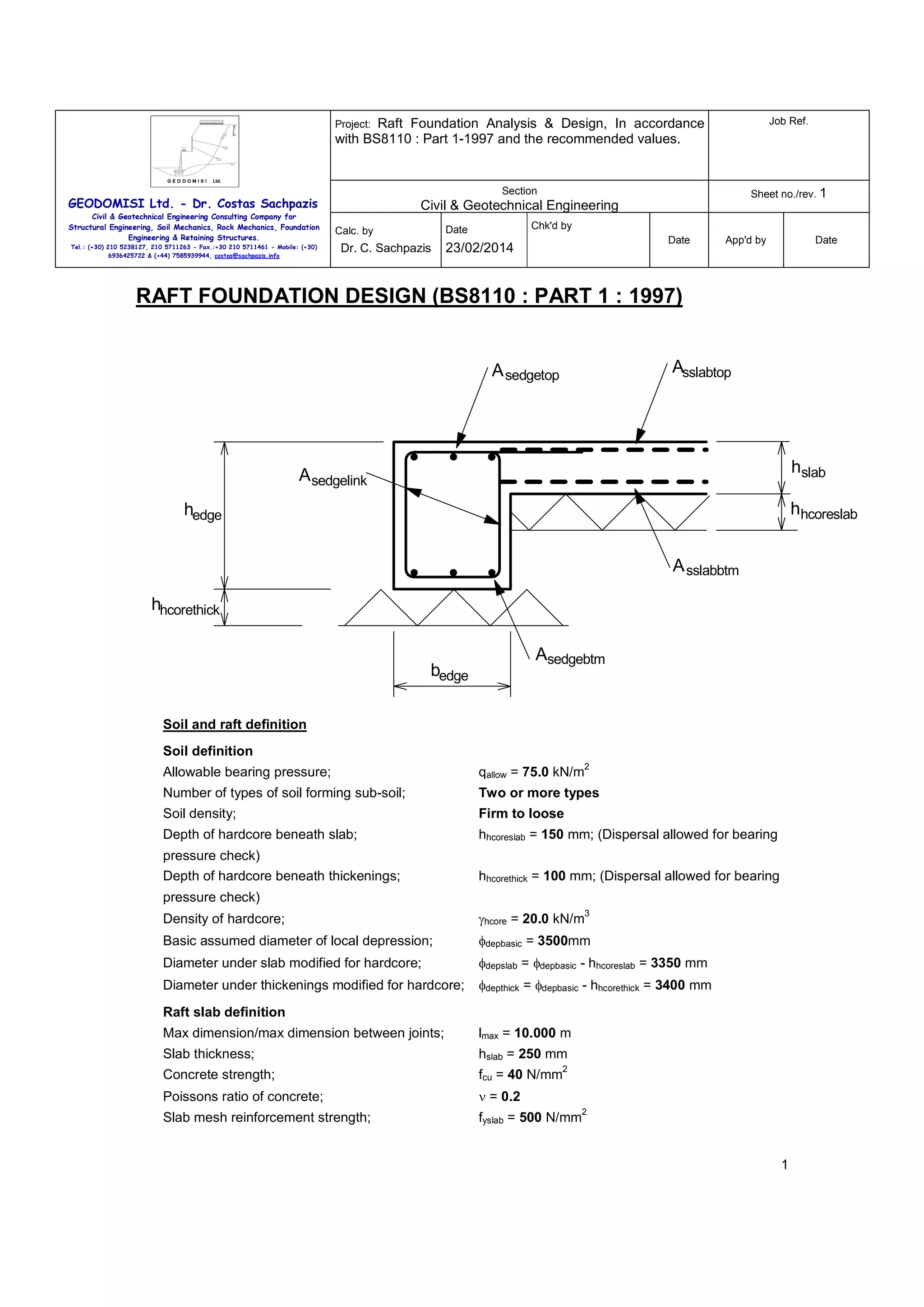
![Raft Foundation Analysis & Design, In accordance
with BS8110 : Part 1-1997 and the recommended values.
Job Ref.
Section
Sheet no./rev. 1
Project:
GEODOMISI Ltd. - Dr. Costas Sachpazis
Civil & Geotechnical Engineering
Civil & Geotechnical Engineering Consulting Company for
Structural Engineering, Soil Mechanics, Rock Mechanics, Foundation
Engineering & Retaining Structures.
Calc. by
Dr. C. Sachpazis
Tel.: (+30) 210 5238127, 210 5711263 - Fax.:+30 210 5711461 - Mobile: (+30)
6936425722 & (+44) 7585939944, costas@sachpazis.info
Chk'd by
Date
Date
23/02/2014
App'd by
Date
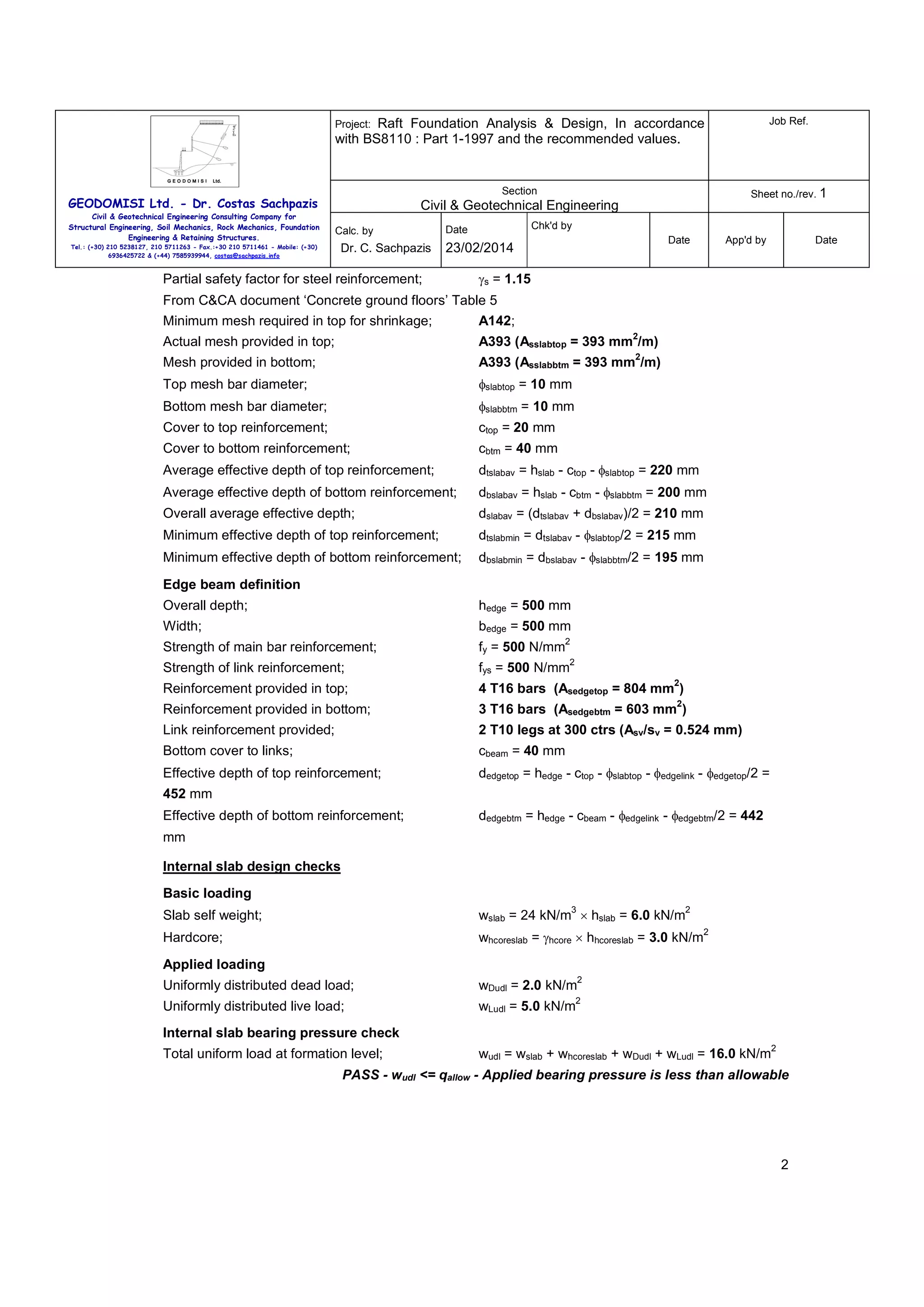
From BS8110-1:1997 - Table 3.8;
Design concrete shear strength;
vc = 0.490 N/mm
2
PASS - v <= vc - Shear capacity of the slab is adequate
Internal slab deflection check
Basic allowable span to depth ratio;
Ratiobasic = 26.0
Moment factor;
Mfactor = MΣc/dbslabav = 0.115 N/mm
Steel service stress;
fs = 2/3 × fyslab × Asslabbtmbend/Asslabbtm = 47.109
N/mm
2
2
2
2
MFslab = min(2.0, 0.55 + [(477N/mm - fs)/(120 ×
Modification factor;
2
(0.9N/mm + Mfactor))])
MFslab = 2.000
Modified allowable span to depth ratio;
Ratioallow = Ratiobasic × MFslab = 52.000
Actual span to depth ratio;
Ratioactual = lslab/ dbslabav = 17.850
PASS - Ratioactual <= Ratioallow - Slab span to depth ratio is adequate
Edge beam design checks
Basic loading
2
whcorethick = γhcore × hhcorethick = 2.0 kN/m
Hardcore;
3
wedge = 24 kN/m × hedge × bedge = 6.0 kN/m
Edge beam self weight;
Edge beam bearing pressure check
Effective bearing width of edge beam;
bbearing = bedge = 500 mm
Total uniform load at formation level;
wudledge = wDudl+wLudl+wedge/bbearing+whcorethick = 21.0
2
kN/m
PASS - wudledge <= qallow - Applied bearing pressure is less than allowable
Edge beam bending check
Divider for moments due to udl’s;
βudl = 10.0
Applied bending moments
Span of edge beam;
ledge = φdepthick + dedgetop = 3852 mm
Ultimate self weight udl;
wedgeult = 1.4 × wedge = 8.4 kN/m
Ultimate slab udl (approx);
wedgeslab = max(0 kN/m, 1.4×wslab×((φdepthick/2 × 3/4)-
bedge)) = 6.5 kN/m
2
Self weight and slab bending moment;
Medgesw = (wedgeult + wedgeslab) × ledge /βudl = 22.1 kNm
Self weight shear force;
Vedgesw = (wedgeult + wedgeslab) × ledge/2 = 28.7 kN
Moments due to applied uniformly distributed loads
Ultimate udl (approx);
wedgeudl = wudlult × φdepthick/2 × 3/4 = 13.8 kN/m
Bending moment;
Medgeudl = wedgeudl × ledge /βudl = 20.4 kNm
Shear force;
Vedgeudl = wedgeudl × ledge/2 = 26.5 kN
2
Resultant moments and shears
Total moment (hogging and sagging);
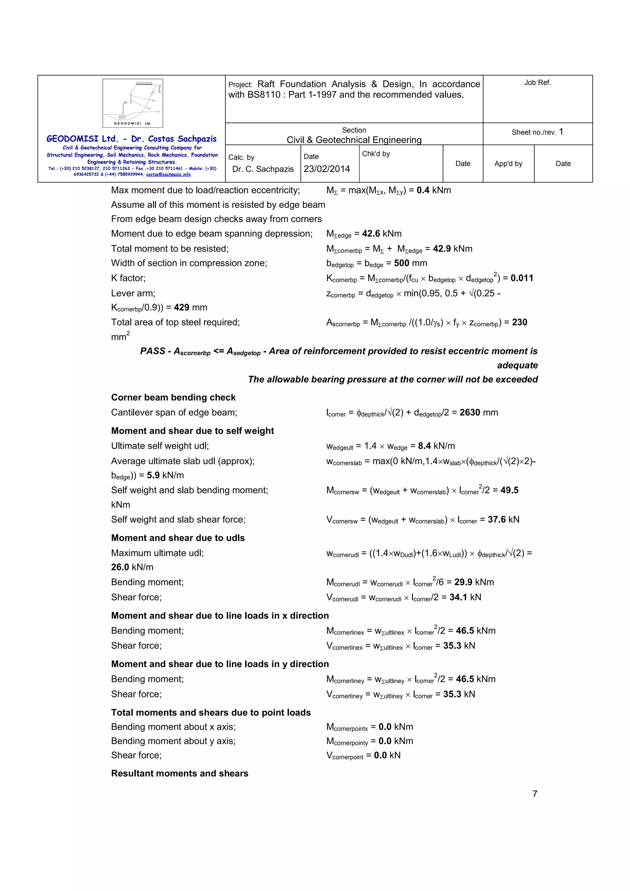
MΣedge = 42.6 kNm
4](https://image.slidesharecdn.com/sachpazisraftfoundationdesignbs8110part1-1997plainslabwithedgewallloadexample-140222155842-phpapp02/75/Sachpazis-Raft-Foundation-Analysis-Design-BS8110-part-1-1997_plain-slab-with-edge-wall-load-example-4-2048.jpg)
![Raft Foundation Analysis & Design, In accordance
with BS8110 : Part 1-1997 and the recommended values.
Job Ref.
Section
Sheet no./rev. 1
Project:
GEODOMISI Ltd. - Dr. Costas Sachpazis
Civil & Geotechnical Engineering Consulting Company for
Structural Engineering, Soil Mechanics, Rock Mechanics, Foundation
Engineering & Retaining Structures.
Tel.: (+30) 210 5238127, 210 5711263 - Fax.:+30 210 5711461 - Mobile: (+30)
6936425722 & (+44) 7585939944, costas@sachpazis.info
Civil & Geotechnical Engineering
Calc. by
Dr. C. Sachpazis
Chk'd by
Date
23/02/2014
Date
App'd by
Date
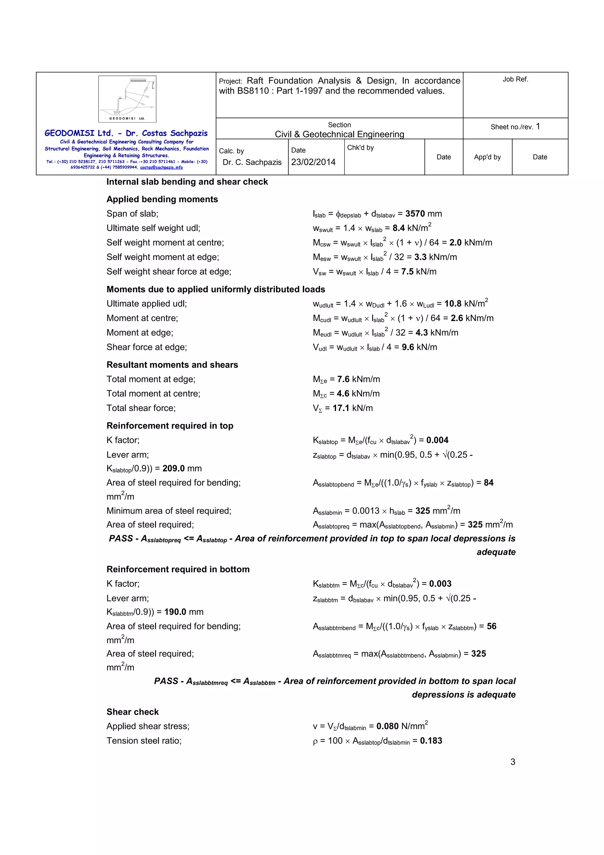
Corner design checks
Basic loading
Corner load number 1
Load type;
Line load in x direction
Dead load;
wDcorner1 = 9.6 kN/m
Live load;
wLcorner1 = 0.0 kN/m
Ultimate load;
wultcorner1 = 1.4 × wDcorner1 + 1.6 × wLcorner1 = 13.4
kN/m
Centroid of load from outside face of raft;
ycorner1 = 100 mm
Corner load number 2
Load type;
Line load in y direction
Dead load;
wDcorner2 = 9.6 kN/m
Live load;
wLcorner2 = 0.0 kN/m
Ultimate load;
wultcorner2 = 1.4 × wDcorner2 + 1.6 × wLcorner2 = 13.4
kN/m
Centroid of load from outside face of raft;
xcorner2 = 100 mm
Corner bearing pressure check
Total uniform load at formation level;
wudlcorner = wDudl+wLudl+wedge/bbearing+whcorethick = 21.0
2
kN/m
Net bearing press avail to resist line/point loads;
2
qnetcorner = qallow - wudlcorner = 54.0 kN/m
Total line/point loads
Total unfactored line load in x direction;
wΣlinex = 9.6 kN/m
Total ultimate line load in x direction;
wΣultlinex =13.4 kN/m
Total unfactored line load in y direction;
wΣliney = 9.6 kN/m
Total ultimate line load in y direction;
wΣultliney = 13.4 kN/m
Total unfactored point load;
wΣpoint = 0.0 kN
Total ultimate point load;
wΣultpoint = 0.0 kN
Length of side of sq reqd to resist line/point loads;
pcorner
2
=[wΣlinex+wΣliney+√((wΣlinex+wΣliney) +4×qnetcorner×wΣpoint)]/(2×qnetcorner)
pcorner = 356 mm
Bending moment about x-axis due to load/reaction eccentricity
Moment due to load 1 (x line);
Mx1 = max(0 kNm, wultcorner1 × pcorner × (pcorner/2 -
ycorner1)) = 0.4 kNm
Total moment about x axis;
MΣx = 0.4 kNm
Bending moment about y-axis due to load/reaction eccentricity
Moment due to load 2 (y line);
My2 = max(0 kNm, wultcorner2 × pcorner × (pcorner/2 -
xcorner2)) = 0.4 kNm
Total moment about y axis;
MΣy = 0.4 kNm
Check top reinforcement in edge beams for load/reaction eccentric moment
6](https://image.slidesharecdn.com/sachpazisraftfoundationdesignbs8110part1-1997plainslabwithedgewallloadexample-140222155842-phpapp02/75/Sachpazis-Raft-Foundation-Analysis-Design-BS8110-part-1-1997_plain-slab-with-edge-wall-load-example-6-2048.jpg)
![Raft Foundation Analysis & Design, In accordance
with BS8110 : Part 1-1997 and the recommended values.
Job Ref.
Section
Sheet no./rev. 1
Project:
GEODOMISI Ltd. - Dr. Costas Sachpazis
Civil & Geotechnical Engineering Consulting Company for
Structural Engineering, Soil Mechanics, Rock Mechanics, Foundation
Engineering & Retaining Structures.
Tel.: (+30) 210 5238127, 210 5711263 - Fax.:+30 210 5711461 - Mobile: (+30)
6936425722 & (+44) 7585939944, costas@sachpazis.info
Civil & Geotechnical Engineering
Calc. by
Dr. C. Sachpazis
23/02/2014
Date
App'd by
Date
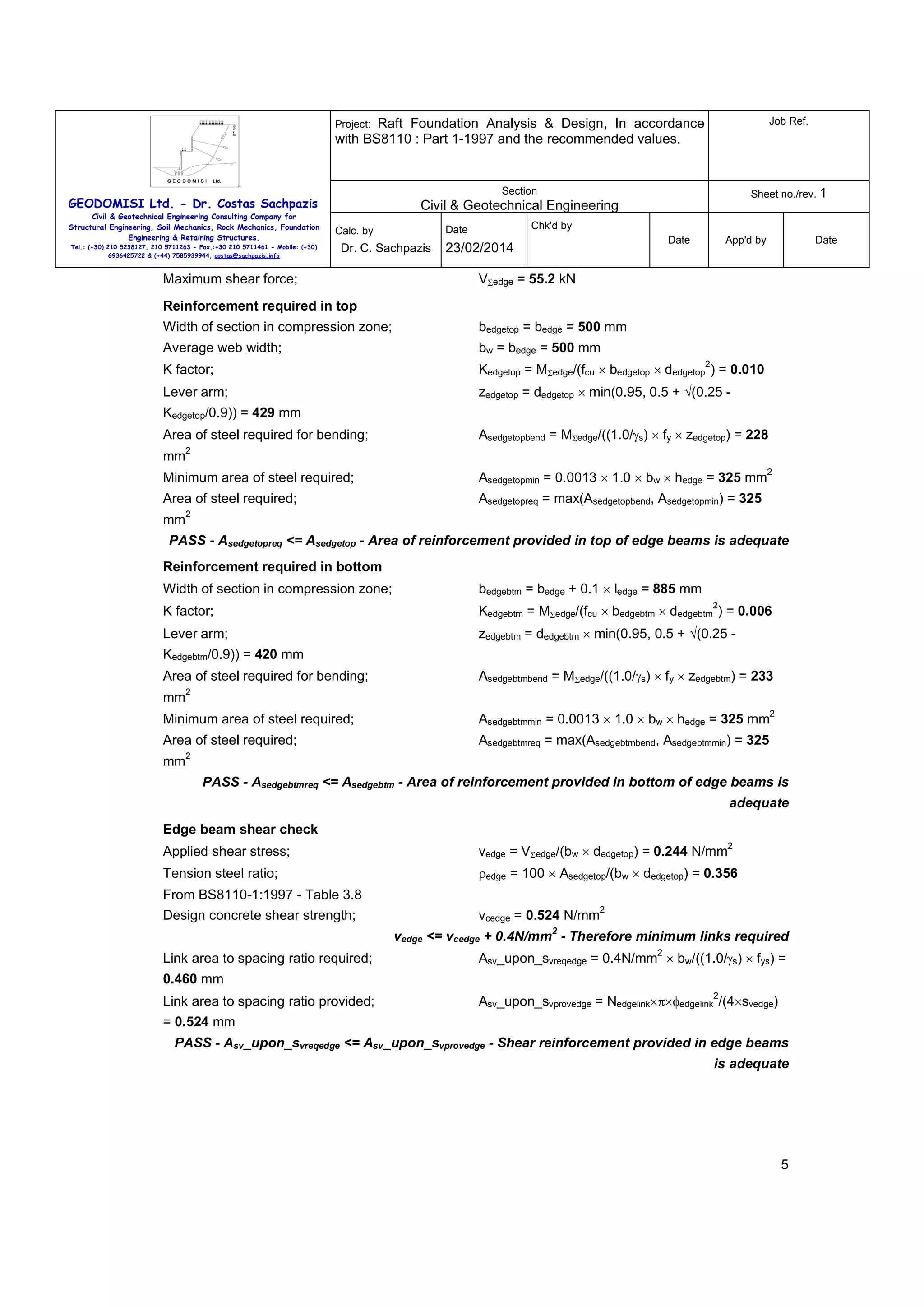
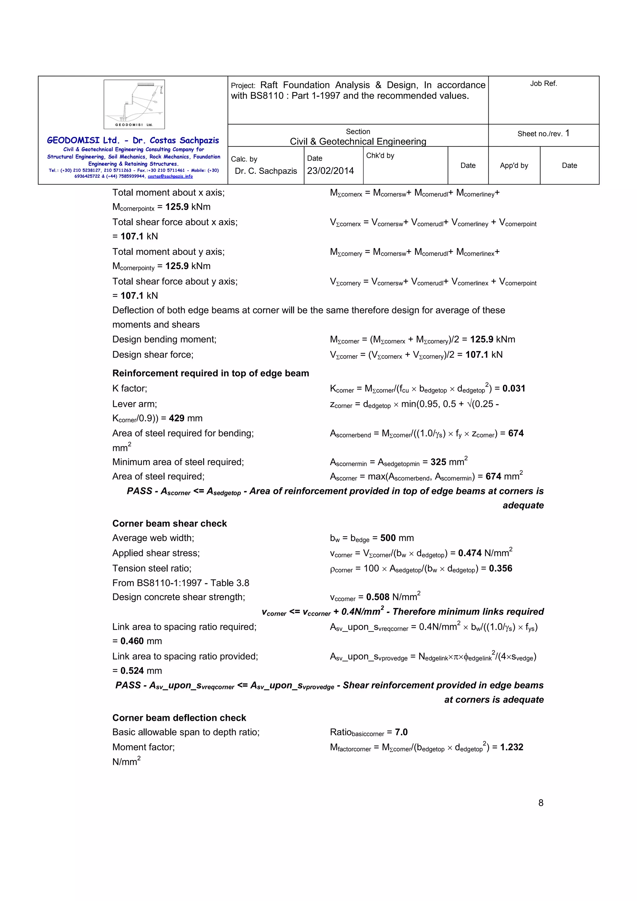
fscorner = 2/3 × fy × Ascornerbend/Asedgetop = 279.448
Steel service stress;
N/mm
Chk'd by
Date
2
2
MFcorner=min(2.0,0.55+[(477N/mm -
Modification factor;
2
fscorner)/(120×(0.9N/mm +Mfactorcorner))])
MFcorner = 1.322
Modified allowable span to depth ratio;
Ratioallowcorner = Ratiobasiccorner × MFcorner = 9.255
Actual span to depth ratio;
Ratioactualcorner = lcorner/ dedgetop = 5.819
PASS - Ratioactualcorner <= Ratioallowcorner - Edge beam span to depth ratio is adequate
9](https://image.slidesharecdn.com/sachpazisraftfoundationdesignbs8110part1-1997plainslabwithedgewallloadexample-140222155842-phpapp02/75/Sachpazis-Raft-Foundation-Analysis-Design-BS8110-part-1-1997_plain-slab-with-edge-wall-load-example-9-2048.jpg)

This document provides a raft foundation design analysis and design in accordance with BS8110 Part 1-1997. It includes definitions of the soil properties, raft geometry, material properties, and loading. It then performs checks for bearing capacity, bending, shear, and deflection for the internal slab and edge beams. Reinforcement is designed for the slab and edge beams to satisfy the various design checks.


![[BROCHURE] Italy Tour Project | @SlideON](https://cdn.slidesharecdn.com/ss_thumbnails/brochure8-251215152319-2805af68-thumbnail.jpg?width=640&height=640&fit=bounds)


