Downloaded 19 times
![Literature Review
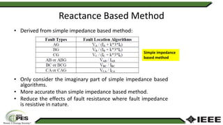
• Some wide-area methods:
References Methods
[19]-[22] Impedance based
[23]-[27] Travelling wave
[28] Fuzzy clustering analysis
[29] Fault model
[25], [30] Wavelet transform](https://image.slidesharecdn.com/presentation-muhdhafizi1-190715154906/85/Wide-Area-Fault-Location-for-Power-Transmission-Network-using-Reactance-Based-Method-5-320.jpg)
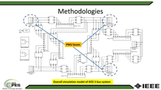
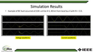


The document discusses a study on wide area fault location methods for power transmission networks, focusing on a reactance-based approach that improves fault detection accuracy. It highlights the importance of fault location in power systems, with the new method allowing for centralized data analysis from various locations using synchrophasors. Simulation results indicated that the reactance method outperforms traditional impedance methods, with plans for future enhancements to improve accuracy further.