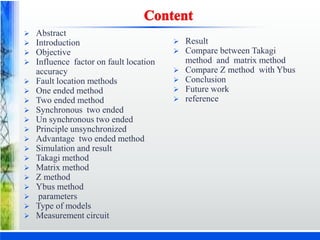
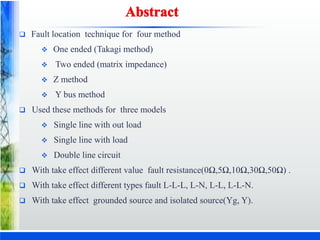
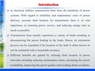
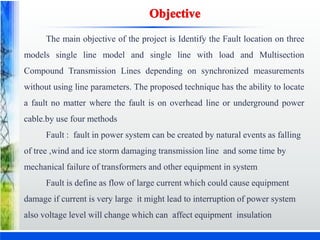
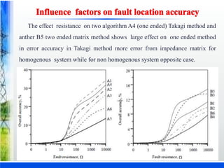
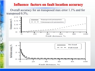
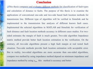
By
Mohammed Shamkhy Shareef
1005-14-743215 , M.E- PS
Under the guidance of
Mr. CH. Siva Kumar
Assistant Professor, EED, UCE, OU
DEPARTMENT OF ELECTRICAL ENGINEERING
UNIVERSITY COLLEGE OF ENGINEERING
OSMANIA UNIVERSITY, HYDERABAD- 500007
TELANGANA STATE, INDIA
2016
 Abstract
 Introduction
 Objective
 Influence factor on fault location
accuracy
 Fault location methods
 One ended method
 Two ended method
 Synchronous two ended
 Un synchronous two ended
 Principle unsynchronized
 Advantage two ended method
 Simulation and result
 Takagi method
 Matrix method
 Z method
 Ybus method
 parameters
 Type of models
 Measurement circuit
 Result
 Compare between Takagi
method and matrix method
 Compare Z method with Ybus
 Conclusion
 Future work
 reference
 Fault location technique for four method
 One ended (Takagi method)
 Two ended (matrix impedance)
 Z method
 Y bus method
 Used these methods for three models
 Single line with out load
 Single line with load
 Double line circuit
 With take effect different value fault resistance(0Ω,5Ω,10Ω,30Ω,50Ω) .
 With take effect different types fault L-L-L, L-N, L-L, L-L-N.
 With take effect grounded source and isolated source(Yg, Y).
 In electrical utilities, transmission lines form the backbone of power
systems. With regard to reliability and maintenance costs of power
delivery, accurate fault location for transmission lines is of vital
importance in restoring power service, and reducing outage time as
much as possible.
 Transmission lines usually experience a variety of faults resulting in
disconnecting the power feeding to the loads. Hence, its restoration
process can be expedited if the location of the fault is either known or
can be estimated with a reasonable accuracy.
 Different benefits are gained by utilizing fault locators in power
networks including reducing maintenance times, increasing the power
availability, improving the power quality and avoiding future accidents.
The main objective of the project is Identify the Fault location on three
models single line model and single line with load and Multisection
Compound Transmission Lines depending on synchronized measurements
without using line parameters. The proposed technique has the ability to locate
a fault no matter where the fault is on overhead line or underground power
cable.by use four methods
Fault : fault in power system can be created by natural events as falling
of tree ,wind and ice storm damaging transmission line and some time by
mechanical failure of transformers and other equipment in system
Fault is define as flow of large current which could cause equipment
damage if current is very large it might lead to interruption of power system
also voltage level will change which can affect equipment insulation
The effect resistance on two algorithm A4 (one ended) Takagi method and
anther B5 two ended matrix method shows large effect on one ended method
in error accuracy in Takagi method more error from impedance matrix for
homogenous system while for non homogenous system opposite case.
Overall accuracy for un transposed max error 1.1% and for
transposed 0.3%.
 Determine fault distance by calculated impedance of T.L as seen from
one line terminal from apparent impedance seen by looking from one
end of line.
 Advantage for this method no communication of data is needed
between line terminal and simple
 Used voltage and current data from one end of T.L only
 Affected by fault resistance
 Zs=Vs/Is assume Rf=0
 Apparent impedance equal to +Ve impedance ZL1of segment by
distance m
 Zs=m*ZLI
 Must taken account +Ve if not take ,calculated will wrong
 Vs/Is=m*ZL1
 Vs=Is*m*Zl1*Rf*If
 Then m=Vs/(Is*Zl1*Rf*If)
 where m per unit distance of fault location.
 example for one ended method:
 simple reactance method Takagi method Modified Takagi method
Wisziewski method Saha method
 Synchronous:
 Digital measurement at different line terminal
can be performed synchronous if GPS is
available other wise or in case of loss of signal
from GPS digital measurement from line
terminal as acquired unsynchronized and do
not have common time
 Synchronous pharos measurement acquired by
gaps based on relay or PMU which use
common time reference for synchronous
 Use phasor based method
 Two source VS, VR , Two part M, 1-M
 Where m fault occur ZL actual impedance for total line assume have
sample at along transmission line where change V,I that meaning
change Z
 It’s necessary find impedance at each point Zi for each variable Ii and
Vi for each point for sample, then
 Zi=Vi/Ii
 To find fault location for any point may be occur fault notes M
represents to fault location, but calculated for all sample that meaning
enter include loop but it’s possible find M by analysis circuit as
 Vf =Vs-M*ZL*Is from send side
 Vf =Vr-(l-M)*Ir*ZL from receive
 Where Vf voltage fault Vs-M*ZL*Is=Vr-(l-M)*Ir*ZL
 M= (Vs-Vr+l*ZL*Ir)/ (ZL*(Is+Ir)
 Now M is known and (1-M) also known
 For one side Vr=0,Ir=O then
 M=Vs/ZL*Is
 example for two ended method:
 Matrix impedance method
 Negative sequence method
Vf=m*z∗ 𝑰𝒔
Vf=Vr-(1-m)z∗ 𝑰𝒓
Vs-Vr+z∗ 𝑰𝒓 = 𝒎 ∗ 𝒛 ∗ (𝑰𝒔 + 𝑰𝒓)
Vs-Vr=mZL∗ 𝑰𝒔 −(1-m)ZL∗ 𝑰𝒓
By multiplying operator synchronization ej𝜹
Vs-Vr∗ 𝒆𝒋𝜹=mZL∗ 𝑰𝒔 −(1-m)ZL∗ 𝑰𝒓 ∗ 𝒆𝒋𝜹
By multplying receiving end data ej𝜽
Vs-Vr∗ 𝒆𝒋 𝜹 + 𝜽 =mK1+(m-1)K2∗ 𝒆𝒋 𝜹 + 𝜽

𝝏𝒎
𝝏𝜽
=Vr∗ 𝒔𝒊𝒏 𝜹 + 𝜽 +(m-1)K2 𝒔𝒊𝒏 𝜹 + 𝜽 /(𝐊𝟏 + 𝐊𝟐 𝐜𝐨𝐬
𝜹 + 𝜽 )
 In case of two end unsynchronized measurement the sampling instants at A
and B ends(small circles) do not coincide due to lack of GPS control
 As a result of not using GPS control a certain random shift(∆𝑇𝐵 − 𝐴) exists
between sampling instants of both ends
 Instant at which fault is detected considered time stamp Ta=0 at bus A and
tB=o at bus B we notes do not coincide
 The measurements from both ends do not have common time base
 In order to assure common base one has to take measurements from
particular end as base (terminal B)
 While for other terminal (terminal A) needs to introduce respective
alignment
 For formulation FL algorithm for phasors of measured quantities should be
done by multiplying all phasors from terminal A by synchronization
operator ej𝛿,where 𝛿 is synchronization angle.
Homogeneous and non homogeneous
 Homogeneous line:
transmission line where impedance is
distributed uniformly on the whole length
In the thesis using non homogeneous
line
 Homogenous system:
transmission system where the local and
remote source impedance have same system
angle as line impedance
In the thesis using non homogeneous
line
 Non homogenous system(different angle)
 Non homogenous line(different R,L,C)
 Un transposed
 No mutual coupling
 Load impedance constant
 Shunt capacitance is neglected
Takagi impedance based algorithm, with use pre-fault and fault data to reducing the effect
of load flow and minimizing the effect of fault resistance, fault location algorithm by Takagi
method calculates the reactance of faulty line using one- terminal voltage and current data of the
transmission line the Takagi method introduces superimposed current ( Isup) to eliminate the
effect of power flow.
Vs=m*ZL1*Is + Rf * If
𝐼𝑠𝑢𝑝 = 𝐼𝑓 − 𝐼 𝑝𝑟𝑒 If complex number (If) and (𝐼𝑠𝑢𝑝
∗
) have the same angle as (Rf) in a
homogenous system will a multiplication of (𝐼𝑠𝑢𝑝
∗
) take the imaginary part of the equation and
eliminate (If)and multiply both side of equation by complex conjugate of Isup and save
imaginary according.
𝑰𝒎 𝑽𝒔 ∗ 𝑰𝒔𝒖𝒑 = 𝒎 ∗ 𝑰𝒎 𝒁 𝑳𝟏 ∗ 𝑰 𝒔 ∗ 𝑰 𝒔𝒖𝒑
∗ + 𝑰𝒎(𝑹 𝒇 + 𝑰 𝒇 + 𝑰 𝒔𝒖𝒑
∗ )
𝒎 =
𝑰𝒎(𝑽 𝒔∗𝑰 𝒔𝒖𝒑
∗ )
𝑰𝒎 𝒁 𝑳𝟏∗𝑰 𝒔∗𝑰 𝒔𝒖𝒑
∗
Takagi method, one-terminal fault method, simply assumes that the three sequences
network distribution factors are equal can lead to undesirable error because the zero-sequence
current (I0) is not known as reliably as the positive-sequence current (I1).
In reality, the fault current is not uniformly distributed when a ground faults occurs
Takagi methods can be improved by applying the 3/2 factor in deriving superposition
current to compensated for the removal unreliable zero-sequence current
𝑰 𝒔𝒖𝒑 = 𝟑
𝟐 𝑰 𝒇 − 𝑰 𝒑𝒓𝒆
Line
Length
(KM)
Type Parameter
1 5 u/g
R=0.024 L=0.256*10-3 C=457.6*10-9
R0=0.036 L0=0.332*10-3 C0=457.6*10-9
2 5 u/g
R=0.016 L=0.268*10-3 C=456.9*10-9
R0=0.0 L0=0.206*10-3 C0=456.9*10-9
3 20 O/H
R=0.038 L=0.896*10-3 C=13.11*10 -9
R0=0.248 L0=2.686*10-3 C0=7.12*10-9
4 20 O/H
R=0.024 L=0.898*10-3 C=13.4*10-9
R0=0.380 L0=3.148*10-3 C0=7.11*10-9
5 20 O/H
R=0.024 L=0.903*10-3 C=12.6*10-9
R0=0.362 L0=3.329*10-3 C0=6.7*10-9
6 20 O/H
R=0.024 L=0.896*10-3 C=13.1*10-9
R0=0.248 L0=2.686*10-3 C0=7.1210-9
From parameters lines non homogenies for different values
for transmission line for R,L,C we use in thesis non homogenies
line and non homogenies system
XL = 2*pi*f*L, XC=1/2*pi*f*C
 Z=R + j(XL-XC)
 𝑍𝑆1 = 0.238 + j 5.72
𝑍 𝑅1 = 0.238 + j 6.19
𝐸𝑆 = 1∠10
𝐸 𝑅= 1∠0
Angle for send side 10 while for receive side 0 then system is
called non homogenies system.
The total length of the transmission line is 90 Km with 6
sections different underground and overhead transmission line,
model for line transmission line has 6 block with two source
have parameter with length 5km, block2=5km, block3=20km,
block4 =20km, block 5=20km and Block6=20km
Model double circuit line has 6 sections for each line, two
cables underground and four overhead lines different length and
different parameters with two source 132kV, 50Hz length
L1=5KM, L2=5KM, L3=20KM, L4=20KM, L5=20KM,
L6=20KMin in parallel figure.4.5 have also block for
measurement along transmission line with two source138kV can
measured voltage at location 5(70) effect from fault AN at block 5(70km) for
single line without load use grounded system Yg
Figure shows measured voltage at location 5(70) effect from fault AN at
location 5(70km) for single line without load and fault location occurred at
same point measuring fault AN dropped to zero while another phases B and C
voltage RMS increased for phase B=95KV for C=90.5kVthis cause problem
for damage equipment insulation where root mean square
voltage=Vm/√2=80kVforsinewave R.M.S=113/√2=80kV. grounded source
Yg for neutral source that meaning some impedance in neutral and for current
Ia=fault current Ib=0,Ic=0 and we can use for detection fault earth fault relay
but sensitive is very small therefore from better use over current relay.
Measured voltage at location 4(50km) effect from fault BCN at location 5(70) km
for single line without load use grounded system Yg
isolated or un grounding neutral system(Y)
For isolated system or ungrounded system the neutral is not connected to the
ground the voltage of the neutral is not fixed and may float freely if occur fault
at single line to ground fault then healthy phases will increase to line voltage
1.372 times which cause insulator breakdown in this case not use over current
protection and use earth fault relay in ideal case VA=0, VB= VC= V line if
fault occur at phase AN phase ground.
Measured voltage at location1(5km) for AN fault while point fault location at
location5 (70km)for isolated system Y.
Measured voltage at location 6(90km) effect from AN fault at location 5(70km)
with single line without load
Figure shows fault type single phase ground AN is dropped to 2.239kV while
another phases B, C increase to phase B=141.5kV and phase C=142kVthat meaning
80kV by 3 that mean VA=0 and VB=VLINE ,Vc=VLINE for ideal case ungrounded
system or called isolated system fault location and device measuring 20km after
location fault therefor dropped to 2.239kV and start from zero to 1sec as time and
where fault occur. Figure shows the voltage at location 6(90km) effect from fault AN at
location 5(70km) for single line without load may be lead to damage equipment
insulation if equipment’s are design as voltage phase where root mean square voltage
=Vm/√2=80kV for sine wave in figure we can see that 138KV phase to phase RMS,
that mean Vm=138* 2/√3 = 113kV then R.M.S=113/√2=80kV as phase voltage RMS
in line voltage RMS 80*. 3 =138kV grounded source Y for neutral source that
meaning no impedance in neutral isolated system and for current IA=fault current
ground IB=0,Ic=0at point fault location5(70) for detection fault by use earth fault relay
as protection.
Measured voltage at location 5(70km) effect from fault ABC at location 5(70km)
use isolated system Y
s
Fault resistance 0.001and 5 Ohms at 70km fault location
Type Fault Measured Location Actual Location Error%
ABC 70.0065 70 0.0072
AN 70.0001 70 6.8e-5
BC 70.0068 70 0.0075
BCN 70.0065 70 0.0072
Type Fault Measured Location Actual Location Error%
ABC 70.00130 70 0.0145
AN 70.0001 70 1.3e-4
BC 70.0135 70 0.0150
BCN 70.0131 70 0.0143
Fault resistance 0.001 and 50 Ohms at 70km fault location
Type Fault Measured Location Actual Location Error%
ABC 70.0865 70 0.0961
AN 70.003 70 0.0037
BC 70.0063 70 0.007
BCN 70.003 70 0.0037
Type Fault Measured Location Actual Location Error%
ABC 70.4323 70 0.4803
AN 70.0160 70 0.0184
BC 70.0313 70 0.0348
BCN 70.0165 70 0.0185
Type Fault Measured Location Actual Location Error%
ABC 70.4979 70 0.5532
AN 70.430 70 0.5534
BC 70.4974 70 0.5530
BCN 70.5030 70 0.5599
Fault resistance 0.001 and 5 Ohms at 70km fault location
Type Fault Measured Location Actual Location Error%
ABC 70.9957 70 1.1064
AN 70.9602 70 1.0669
BC 70.9957 70 1.10641
BCN 71.0060 70 1.1178
 Z impedance method no more different between with load
and with out load
 Y bus method different between with load and with out load
because load will change voltage so Y value will change
 Y bus method take in to account for calculated Zl,Z0 positive
impedance and negative impedance
 Positive sequence and negative sequence there get good
accuracy in Ybus
This thesis compares and evaluates different methods for classification of fault types
and calculation of distance to faults. The purpose of this thesis is to examine the
applications of conventional one-side and two-side based fault location methods for
transmission line. Different type of algorithm will be verified in Simulink and be
implemented to the transmission line analyses of different known fault cases.
Implemented the selected algorithms in MATLAB and Simulink for verification of
fault distance and fault location methods accuracy in different cases studies. For two-
sided estimates the margin of fault is much greater, Two-side algorithm Impedance
matrix method provide better fault location estimation in the verification. On the
contrary, all two-side algorithms present a high fault margin at real tested fault
situation. Two-side methods provide fault location estimation with acceptable error.
But in reality, two-sided algorithms are more accurate than one-sided algorithms,
compare two method by using impedance method depend on minimum impedance and
impedance method by using ybus this method is accuracy and better
Where increase length for transmission line will increased error and
increase fault current at point fault location
Accuracy of Takagi method is 0.5% and for matrix method 3.3% for un
homogenies system.
Accuracy of ybus method is 0.05% and for impedance method 1.4% for un
homogenies system.
Where increased resistance fault will increase voltage and decrease current
at point fault location
Used ybus method for simulation gives small error
Using grounding Yg or isolated system Y not effected at fault location as
distance while effect Y on fault ground as L-N ,L-L-N where increased value
voltage at fault for healthy phases to line voltage 1.732 times normal value
while for Yg same phase voltag
Future work
Future work
Study fault location for three model for homogenies system by use Takagi
method and matrix method with and without presence mutual coupling.
REFERENCE
 [1] A.Nagoor Kanai, “Power system analysis”, the Institute of Electrical and Electronics
Engineers”, Inc.,RBA Publications, First Edition1999.reprint July 2013.
 [2] www.mwftr.com “lecture notes on fault detection and location in distribution system”
Charles kim 2010.
 [3] Karl Zimmerman and David Costello “Impedance based fault location experience”,
Proceeding of the 58 th Annual conference for protective relay Engineers, college station
,TX,April.SEL Journal of Reliable Power, Volume 1,Nnmber 1,July 2010.
 [4]Alkm Capar,and Aysen Basa Arsoy,IEEE“valuating Accuracy of fault location Algorithms
Based on Terminal current and voltage Data”International Journal of Electrical Engineering vol
.3,No.3, June 2015.
 [5] Chih-Wen Liu, Tzu-Chiao Lin, Chi-Shan Yu, and Jun-Zhe Yang” A Fault Location
Technique for Two-Terminal Multisection Compound Transmission Lines Using Synchronized
Phasor Measurements” IEEE TRANSACTIONS ON SMART GRID, VOL. 3, NO. 1, MARCH
2012.
 [6]Nagy I.Elkalashy,Tamer A.Kawady,’Unsynchronized fault location Technique for Double –
Circuit Transmission Systems Independent of line Parameters”IEEE Tranasaction On Power
Delivery10.1109/TPWRD.2015
 [7]Adly A.Girgis and David G.Hart ,William L.”ANEW FAULT LOCATION TECHNIQUE
FOR TWO AND THREE TERMINALS”IEEE Transaction On Power Delivery,Vol.7
No.1,January 1992.
[8] D. Novosel, D.G. Hart, E. Udren, J. Garitty,” Unsynchronised two-terminal fault
location estimation”, IEEE Transaction On Power DeliveryVol.11,No.1,January 1996.
[9] Rameshkumar.C. Mishra, Muneeb Ahmad ,P.M. Deoghare and Sanjaykumar
Singh “Impedance Based Measurement Technique for Transmission Line Fault
Location” Internatinal Journal Of Recent Advancees in Engineering and
Technology(IJRAET) Vol.3,Issue.8.2015.
[10] Giovanni Manassero and Jr.Eduardo Cesar Senger “Fault Location System For
Multiterminal transmission lines” IEEE Transactions On power Delivery,vol..25, No.3
July 2010..
[11] Badri Ram and D.N.Vishwakarma ”power system protection and switch gear
“McGraw Hill Education(India)Private Limited, Seventh reprint 2013.
[12]S.SIVAAGARAJU and B.V RAMI REDDY”Electric power System
Analysis”UNIVERSITY SCIENCE PRESS,Laxmi Publication Private Limited,2013.
[13]http://nptel.ac.in/courses “symmetrical fault analysis”2014
Fault location  for transmission line

Fault location for transmission line

  • 1.
    By Mohammed Shamkhy Shareef 1005-14-743215, M.E- PS Under the guidance of Mr. CH. Siva Kumar Assistant Professor, EED, UCE, OU DEPARTMENT OF ELECTRICAL ENGINEERING UNIVERSITY COLLEGE OF ENGINEERING OSMANIA UNIVERSITY, HYDERABAD- 500007 TELANGANA STATE, INDIA 2016
  • 2.
     Abstract  Introduction Objective  Influence factor on fault location accuracy  Fault location methods  One ended method  Two ended method  Synchronous two ended  Un synchronous two ended  Principle unsynchronized  Advantage two ended method  Simulation and result  Takagi method  Matrix method  Z method  Ybus method  parameters  Type of models  Measurement circuit  Result  Compare between Takagi method and matrix method  Compare Z method with Ybus  Conclusion  Future work  reference
  • 3.
     Fault locationtechnique for four method  One ended (Takagi method)  Two ended (matrix impedance)  Z method  Y bus method  Used these methods for three models  Single line with out load  Single line with load  Double line circuit  With take effect different value fault resistance(0Ω,5Ω,10Ω,30Ω,50Ω) .  With take effect different types fault L-L-L, L-N, L-L, L-L-N.  With take effect grounded source and isolated source(Yg, Y).
  • 4.
     In electricalutilities, transmission lines form the backbone of power systems. With regard to reliability and maintenance costs of power delivery, accurate fault location for transmission lines is of vital importance in restoring power service, and reducing outage time as much as possible.  Transmission lines usually experience a variety of faults resulting in disconnecting the power feeding to the loads. Hence, its restoration process can be expedited if the location of the fault is either known or can be estimated with a reasonable accuracy.  Different benefits are gained by utilizing fault locators in power networks including reducing maintenance times, increasing the power availability, improving the power quality and avoiding future accidents.
  • 5.
    The main objectiveof the project is Identify the Fault location on three models single line model and single line with load and Multisection Compound Transmission Lines depending on synchronized measurements without using line parameters. The proposed technique has the ability to locate a fault no matter where the fault is on overhead line or underground power cable.by use four methods Fault : fault in power system can be created by natural events as falling of tree ,wind and ice storm damaging transmission line and some time by mechanical failure of transformers and other equipment in system Fault is define as flow of large current which could cause equipment damage if current is very large it might lead to interruption of power system also voltage level will change which can affect equipment insulation
  • 6.
    The effect resistanceon two algorithm A4 (one ended) Takagi method and anther B5 two ended matrix method shows large effect on one ended method in error accuracy in Takagi method more error from impedance matrix for homogenous system while for non homogenous system opposite case.
  • 7.
    Overall accuracy forun transposed max error 1.1% and for transposed 0.3%.
  • 9.
     Determine faultdistance by calculated impedance of T.L as seen from one line terminal from apparent impedance seen by looking from one end of line.  Advantage for this method no communication of data is needed between line terminal and simple  Used voltage and current data from one end of T.L only  Affected by fault resistance  Zs=Vs/Is assume Rf=0  Apparent impedance equal to +Ve impedance ZL1of segment by distance m  Zs=m*ZLI  Must taken account +Ve if not take ,calculated will wrong  Vs/Is=m*ZL1  Vs=Is*m*Zl1*Rf*If  Then m=Vs/(Is*Zl1*Rf*If)  where m per unit distance of fault location.  example for one ended method:  simple reactance method Takagi method Modified Takagi method Wisziewski method Saha method
  • 10.
     Synchronous:  Digitalmeasurement at different line terminal can be performed synchronous if GPS is available other wise or in case of loss of signal from GPS digital measurement from line terminal as acquired unsynchronized and do not have common time  Synchronous pharos measurement acquired by gaps based on relay or PMU which use common time reference for synchronous  Use phasor based method
  • 11.
     Two sourceVS, VR , Two part M, 1-M  Where m fault occur ZL actual impedance for total line assume have sample at along transmission line where change V,I that meaning change Z  It’s necessary find impedance at each point Zi for each variable Ii and Vi for each point for sample, then  Zi=Vi/Ii  To find fault location for any point may be occur fault notes M represents to fault location, but calculated for all sample that meaning enter include loop but it’s possible find M by analysis circuit as  Vf =Vs-M*ZL*Is from send side  Vf =Vr-(l-M)*Ir*ZL from receive
  • 12.
     Where Vfvoltage fault Vs-M*ZL*Is=Vr-(l-M)*Ir*ZL  M= (Vs-Vr+l*ZL*Ir)/ (ZL*(Is+Ir)  Now M is known and (1-M) also known  For one side Vr=0,Ir=O then  M=Vs/ZL*Is  example for two ended method:  Matrix impedance method  Negative sequence method
  • 13.
    Vf=m*z∗ 𝑰𝒔 Vf=Vr-(1-m)z∗ 𝑰𝒓 Vs-Vr+z∗𝑰𝒓 = 𝒎 ∗ 𝒛 ∗ (𝑰𝒔 + 𝑰𝒓) Vs-Vr=mZL∗ 𝑰𝒔 −(1-m)ZL∗ 𝑰𝒓 By multiplying operator synchronization ej𝜹 Vs-Vr∗ 𝒆𝒋𝜹=mZL∗ 𝑰𝒔 −(1-m)ZL∗ 𝑰𝒓 ∗ 𝒆𝒋𝜹 By multplying receiving end data ej𝜽 Vs-Vr∗ 𝒆𝒋 𝜹 + 𝜽 =mK1+(m-1)K2∗ 𝒆𝒋 𝜹 + 𝜽  𝝏𝒎 𝝏𝜽 =Vr∗ 𝒔𝒊𝒏 𝜹 + 𝜽 +(m-1)K2 𝒔𝒊𝒏 𝜹 + 𝜽 /(𝐊𝟏 + 𝐊𝟐 𝐜𝐨𝐬 𝜹 + 𝜽 )
  • 14.
     In caseof two end unsynchronized measurement the sampling instants at A and B ends(small circles) do not coincide due to lack of GPS control  As a result of not using GPS control a certain random shift(∆𝑇𝐵 − 𝐴) exists between sampling instants of both ends  Instant at which fault is detected considered time stamp Ta=0 at bus A and tB=o at bus B we notes do not coincide  The measurements from both ends do not have common time base  In order to assure common base one has to take measurements from particular end as base (terminal B)  While for other terminal (terminal A) needs to introduce respective alignment  For formulation FL algorithm for phasors of measured quantities should be done by multiplying all phasors from terminal A by synchronization operator ej𝛿,where 𝛿 is synchronization angle.
  • 15.
    Homogeneous and nonhomogeneous  Homogeneous line: transmission line where impedance is distributed uniformly on the whole length In the thesis using non homogeneous line  Homogenous system: transmission system where the local and remote source impedance have same system angle as line impedance In the thesis using non homogeneous line
  • 16.
     Non homogenoussystem(different angle)  Non homogenous line(different R,L,C)  Un transposed  No mutual coupling  Load impedance constant  Shunt capacitance is neglected
  • 17.
    Takagi impedance basedalgorithm, with use pre-fault and fault data to reducing the effect of load flow and minimizing the effect of fault resistance, fault location algorithm by Takagi method calculates the reactance of faulty line using one- terminal voltage and current data of the transmission line the Takagi method introduces superimposed current ( Isup) to eliminate the effect of power flow. Vs=m*ZL1*Is + Rf * If 𝐼𝑠𝑢𝑝 = 𝐼𝑓 − 𝐼 𝑝𝑟𝑒 If complex number (If) and (𝐼𝑠𝑢𝑝 ∗ ) have the same angle as (Rf) in a homogenous system will a multiplication of (𝐼𝑠𝑢𝑝 ∗ ) take the imaginary part of the equation and eliminate (If)and multiply both side of equation by complex conjugate of Isup and save imaginary according. 𝑰𝒎 𝑽𝒔 ∗ 𝑰𝒔𝒖𝒑 = 𝒎 ∗ 𝑰𝒎 𝒁 𝑳𝟏 ∗ 𝑰 𝒔 ∗ 𝑰 𝒔𝒖𝒑 ∗ + 𝑰𝒎(𝑹 𝒇 + 𝑰 𝒇 + 𝑰 𝒔𝒖𝒑 ∗ ) 𝒎 = 𝑰𝒎(𝑽 𝒔∗𝑰 𝒔𝒖𝒑 ∗ ) 𝑰𝒎 𝒁 𝑳𝟏∗𝑰 𝒔∗𝑰 𝒔𝒖𝒑 ∗ Takagi method, one-terminal fault method, simply assumes that the three sequences network distribution factors are equal can lead to undesirable error because the zero-sequence current (I0) is not known as reliably as the positive-sequence current (I1). In reality, the fault current is not uniformly distributed when a ground faults occurs Takagi methods can be improved by applying the 3/2 factor in deriving superposition current to compensated for the removal unreliable zero-sequence current 𝑰 𝒔𝒖𝒑 = 𝟑 𝟐 𝑰 𝒇 − 𝑰 𝒑𝒓𝒆
  • 18.
    Line Length (KM) Type Parameter 1 5u/g R=0.024 L=0.256*10-3 C=457.6*10-9 R0=0.036 L0=0.332*10-3 C0=457.6*10-9 2 5 u/g R=0.016 L=0.268*10-3 C=456.9*10-9 R0=0.0 L0=0.206*10-3 C0=456.9*10-9 3 20 O/H R=0.038 L=0.896*10-3 C=13.11*10 -9 R0=0.248 L0=2.686*10-3 C0=7.12*10-9 4 20 O/H R=0.024 L=0.898*10-3 C=13.4*10-9 R0=0.380 L0=3.148*10-3 C0=7.11*10-9 5 20 O/H R=0.024 L=0.903*10-3 C=12.6*10-9 R0=0.362 L0=3.329*10-3 C0=6.7*10-9 6 20 O/H R=0.024 L=0.896*10-3 C=13.1*10-9 R0=0.248 L0=2.686*10-3 C0=7.1210-9
  • 19.
    From parameters linesnon homogenies for different values for transmission line for R,L,C we use in thesis non homogenies line and non homogenies system XL = 2*pi*f*L, XC=1/2*pi*f*C  Z=R + j(XL-XC)  𝑍𝑆1 = 0.238 + j 5.72 𝑍 𝑅1 = 0.238 + j 6.19 𝐸𝑆 = 1∠10 𝐸 𝑅= 1∠0 Angle for send side 10 while for receive side 0 then system is called non homogenies system.
  • 20.
    The total lengthof the transmission line is 90 Km with 6 sections different underground and overhead transmission line, model for line transmission line has 6 block with two source have parameter with length 5km, block2=5km, block3=20km, block4 =20km, block 5=20km and Block6=20km
  • 21.
    Model double circuitline has 6 sections for each line, two cables underground and four overhead lines different length and different parameters with two source 132kV, 50Hz length L1=5KM, L2=5KM, L3=20KM, L4=20KM, L5=20KM, L6=20KMin in parallel figure.4.5 have also block for measurement along transmission line with two source138kV can
  • 22.
    measured voltage atlocation 5(70) effect from fault AN at block 5(70km) for single line without load use grounded system Yg Figure shows measured voltage at location 5(70) effect from fault AN at location 5(70km) for single line without load and fault location occurred at same point measuring fault AN dropped to zero while another phases B and C voltage RMS increased for phase B=95KV for C=90.5kVthis cause problem for damage equipment insulation where root mean square voltage=Vm/√2=80kVforsinewave R.M.S=113/√2=80kV. grounded source Yg for neutral source that meaning some impedance in neutral and for current Ia=fault current Ib=0,Ic=0 and we can use for detection fault earth fault relay but sensitive is very small therefore from better use over current relay.
  • 23.
    Measured voltage atlocation 4(50km) effect from fault BCN at location 5(70) km for single line without load use grounded system Yg
  • 24.
    isolated or ungrounding neutral system(Y) For isolated system or ungrounded system the neutral is not connected to the ground the voltage of the neutral is not fixed and may float freely if occur fault at single line to ground fault then healthy phases will increase to line voltage 1.372 times which cause insulator breakdown in this case not use over current protection and use earth fault relay in ideal case VA=0, VB= VC= V line if fault occur at phase AN phase ground.
  • 25.
    Measured voltage atlocation1(5km) for AN fault while point fault location at location5 (70km)for isolated system Y.
  • 26.
    Measured voltage atlocation 6(90km) effect from AN fault at location 5(70km) with single line without load Figure shows fault type single phase ground AN is dropped to 2.239kV while another phases B, C increase to phase B=141.5kV and phase C=142kVthat meaning 80kV by 3 that mean VA=0 and VB=VLINE ,Vc=VLINE for ideal case ungrounded system or called isolated system fault location and device measuring 20km after location fault therefor dropped to 2.239kV and start from zero to 1sec as time and where fault occur. Figure shows the voltage at location 6(90km) effect from fault AN at location 5(70km) for single line without load may be lead to damage equipment insulation if equipment’s are design as voltage phase where root mean square voltage =Vm/√2=80kV for sine wave in figure we can see that 138KV phase to phase RMS, that mean Vm=138* 2/√3 = 113kV then R.M.S=113/√2=80kV as phase voltage RMS in line voltage RMS 80*. 3 =138kV grounded source Y for neutral source that meaning no impedance in neutral isolated system and for current IA=fault current ground IB=0,Ic=0at point fault location5(70) for detection fault by use earth fault relay as protection.
  • 27.
    Measured voltage atlocation 5(70km) effect from fault ABC at location 5(70km) use isolated system Y s
  • 28.
    Fault resistance 0.001and5 Ohms at 70km fault location Type Fault Measured Location Actual Location Error% ABC 70.0065 70 0.0072 AN 70.0001 70 6.8e-5 BC 70.0068 70 0.0075 BCN 70.0065 70 0.0072 Type Fault Measured Location Actual Location Error% ABC 70.00130 70 0.0145 AN 70.0001 70 1.3e-4 BC 70.0135 70 0.0150 BCN 70.0131 70 0.0143
  • 29.
    Fault resistance 0.001and 50 Ohms at 70km fault location Type Fault Measured Location Actual Location Error% ABC 70.0865 70 0.0961 AN 70.003 70 0.0037 BC 70.0063 70 0.007 BCN 70.003 70 0.0037 Type Fault Measured Location Actual Location Error% ABC 70.4323 70 0.4803 AN 70.0160 70 0.0184 BC 70.0313 70 0.0348 BCN 70.0165 70 0.0185
  • 30.
    Type Fault MeasuredLocation Actual Location Error% ABC 70.4979 70 0.5532 AN 70.430 70 0.5534 BC 70.4974 70 0.5530 BCN 70.5030 70 0.5599 Fault resistance 0.001 and 5 Ohms at 70km fault location Type Fault Measured Location Actual Location Error% ABC 70.9957 70 1.1064 AN 70.9602 70 1.0669 BC 70.9957 70 1.10641 BCN 71.0060 70 1.1178
  • 31.
     Z impedancemethod no more different between with load and with out load  Y bus method different between with load and with out load because load will change voltage so Y value will change  Y bus method take in to account for calculated Zl,Z0 positive impedance and negative impedance  Positive sequence and negative sequence there get good accuracy in Ybus
  • 32.
    This thesis comparesand evaluates different methods for classification of fault types and calculation of distance to faults. The purpose of this thesis is to examine the applications of conventional one-side and two-side based fault location methods for transmission line. Different type of algorithm will be verified in Simulink and be implemented to the transmission line analyses of different known fault cases. Implemented the selected algorithms in MATLAB and Simulink for verification of fault distance and fault location methods accuracy in different cases studies. For two- sided estimates the margin of fault is much greater, Two-side algorithm Impedance matrix method provide better fault location estimation in the verification. On the contrary, all two-side algorithms present a high fault margin at real tested fault situation. Two-side methods provide fault location estimation with acceptable error. But in reality, two-sided algorithms are more accurate than one-sided algorithms, compare two method by using impedance method depend on minimum impedance and impedance method by using ybus this method is accuracy and better
  • 33.
    Where increase lengthfor transmission line will increased error and increase fault current at point fault location Accuracy of Takagi method is 0.5% and for matrix method 3.3% for un homogenies system. Accuracy of ybus method is 0.05% and for impedance method 1.4% for un homogenies system. Where increased resistance fault will increase voltage and decrease current at point fault location Used ybus method for simulation gives small error Using grounding Yg or isolated system Y not effected at fault location as distance while effect Y on fault ground as L-N ,L-L-N where increased value voltage at fault for healthy phases to line voltage 1.732 times normal value while for Yg same phase voltag
  • 34.
    Future work Future work Studyfault location for three model for homogenies system by use Takagi method and matrix method with and without presence mutual coupling.
  • 35.
    REFERENCE  [1] A.NagoorKanai, “Power system analysis”, the Institute of Electrical and Electronics Engineers”, Inc.,RBA Publications, First Edition1999.reprint July 2013.  [2] www.mwftr.com “lecture notes on fault detection and location in distribution system” Charles kim 2010.  [3] Karl Zimmerman and David Costello “Impedance based fault location experience”, Proceeding of the 58 th Annual conference for protective relay Engineers, college station ,TX,April.SEL Journal of Reliable Power, Volume 1,Nnmber 1,July 2010.  [4]Alkm Capar,and Aysen Basa Arsoy,IEEE“valuating Accuracy of fault location Algorithms Based on Terminal current and voltage Data”International Journal of Electrical Engineering vol .3,No.3, June 2015.  [5] Chih-Wen Liu, Tzu-Chiao Lin, Chi-Shan Yu, and Jun-Zhe Yang” A Fault Location Technique for Two-Terminal Multisection Compound Transmission Lines Using Synchronized Phasor Measurements” IEEE TRANSACTIONS ON SMART GRID, VOL. 3, NO. 1, MARCH 2012.  [6]Nagy I.Elkalashy,Tamer A.Kawady,’Unsynchronized fault location Technique for Double – Circuit Transmission Systems Independent of line Parameters”IEEE Tranasaction On Power Delivery10.1109/TPWRD.2015  [7]Adly A.Girgis and David G.Hart ,William L.”ANEW FAULT LOCATION TECHNIQUE FOR TWO AND THREE TERMINALS”IEEE Transaction On Power Delivery,Vol.7 No.1,January 1992.
  • 36.
    [8] D. Novosel,D.G. Hart, E. Udren, J. Garitty,” Unsynchronised two-terminal fault location estimation”, IEEE Transaction On Power DeliveryVol.11,No.1,January 1996. [9] Rameshkumar.C. Mishra, Muneeb Ahmad ,P.M. Deoghare and Sanjaykumar Singh “Impedance Based Measurement Technique for Transmission Line Fault Location” Internatinal Journal Of Recent Advancees in Engineering and Technology(IJRAET) Vol.3,Issue.8.2015. [10] Giovanni Manassero and Jr.Eduardo Cesar Senger “Fault Location System For Multiterminal transmission lines” IEEE Transactions On power Delivery,vol..25, No.3 July 2010.. [11] Badri Ram and D.N.Vishwakarma ”power system protection and switch gear “McGraw Hill Education(India)Private Limited, Seventh reprint 2013. [12]S.SIVAAGARAJU and B.V RAMI REDDY”Electric power System Analysis”UNIVERSITY SCIENCE PRESS,Laxmi Publication Private Limited,2013. [13]http://nptel.ac.in/courses “symmetrical fault analysis”2014