The document discusses load management using ABB's Ekip Power Controller integrated into SACE Emax 2 circuit breakers. The controller monitors total power consumption and disconnects non-priority loads to keep average power within contractual limits. It operates in 4 steps: 1) Measuring power, 2) Synchronizing to time intervals, 3) Evaluating if power is too high/low, 4) Managing loads by disconnecting/reconnecting according to priority lists and minimum connection times. This allows optimization of power consumption costs while avoiding plant overloads or inefficiencies.


![ABB | Load management with Ekip Power Controller for SACE Emax 2 5
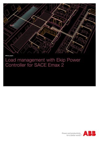
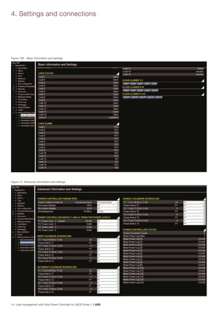
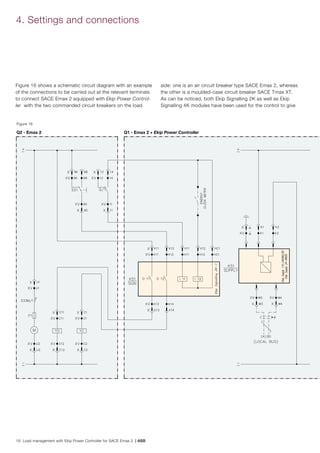
Figure 1
The month’s maximum demand will be the highest among the
demand values recorded over the month.
The smart meter registers only if the value exceeds the previ-
ous maximum demand value. Thus, although the monthly
average demand may be low, the user shall have to pay the
maximum demand charges for the highest value registered
during the month, even if it has occurred for just one record-
ing cycle duration (e.g. 30 minutes).
In an electrical system macro perspective, the growth in the
demand for electricity by the more and more diverse end user
segments along with the timing of their use, has led shortfalls
in capacity to meet demand.
As a solution, the construction of new generation power
plants, to help keep up with energy demands, can prove to
be costly as well as a long wait prospective. Better load man-
agement on the side of the user can help to minimize peak
demands on the utility infrastructures as well as to improve
the utilization of power plant capacities.
The utilities or electricity distribution companies can use
power tariff structures to influence end user consumption
utilizing measures such as: time of use tariffs, penalties on
exceeding allowed maximum demand, correct demand, night
tariffs, and concessions.
Load management is a powerful means of efficiency improve-
ment both for end Users as well as for utility companies.
It is important to keep in mind (from a user's perspective)
that since demand charges constitute a considerable portion
of the electricity bill, there is a real need for integrated load
management to effectively control the maximum demand in
the billing cycle.
T [min]
Power[kVA]
Demand
Power Curve
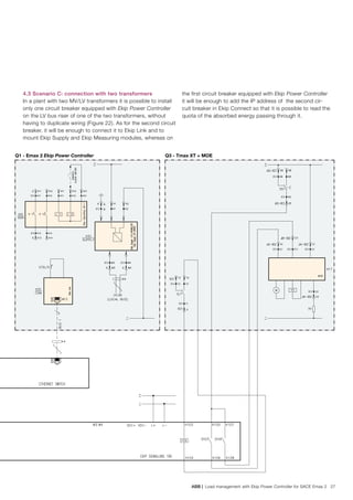
The diagram in Figure 1 illustrates the average power con-
sumed in four different time intervals over a 30-minute period
(see the above formula).
The dashed straight lines show the average power consump-
tion, whereas the continuous curved line shows the actual
power consumption.](https://image.slidesharecdn.com/eaa889f0-a3cd-46bc-af12-4ed0da8afad3-151022214957-lva1-app6892/85/White-paper-7-320.jpg)
![ABB | Load management with Ekip Power Controller for SACE Emax 2 7
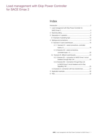
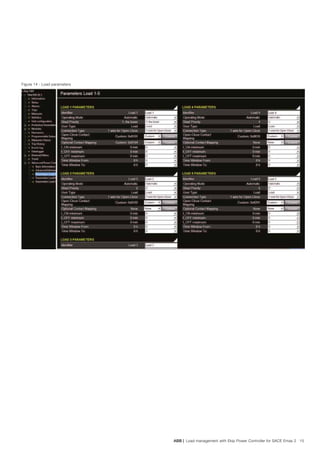
Figure 3
Figure 4
4. Load management: based on the decision resulting from
the evaluation module, the system decides which loads are
to be disconnected or reconnected, in compliance with the
following rules:
- priority – if it is necessary to disconnect a load, and
when more than one load can be chosen for this
operation, the indication and the order given by the
User in the list of the controllable loads is followed:
the first load on the list is typically the least important
for the application or that which can be temporarily
disconnected. The second load immediately follows for
importance and so on. Likewise, when a load must be
reconnected, the algorithm follows the set list in the
reverse order (starting from the last load in the list), that
is starting with the reconnection of the load with the ut-
most priority for the plant. The algorithm complies with
the priority order set by the User, in compliance with
the respected time mentioned below. It also considers
when a breaker is open due to a trip, or if it has been
purposely opened by the user (e.g. maintenance or
shut down).
- respect times – every load may have minimum times in
which it must remain connected (or disconnected) to
avoid damage. Therefore, when choosing the load to
be connected or disconnected, the algorithm will not
consider any load that has just been switched. When
this is the case it jumps to the following load on the list.
- reordering – when a load becomes available again be-
cause its respect time is over, it is connected or discon-
nected according to its position in the list.
It is possible to set the same priority for two or more loads:
this means that they are of the same importance for the plant
and therefore it is not necessary to define which one has to
be disconnected first. In such case, Ekip Power Controller
shall disconnect one or more of these loads, switching the
load which has not been operated for the longest period of
time first. In occurrences when more than one load of the
same priority level is to be disconnected, the controller simply
switches them in order.
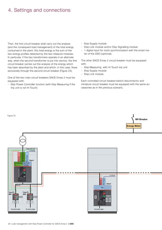
The core of Ekip Power Controller is the evaluation module. It
operates based on the energy demand with reference to the
time elapsed from the beginning of the set reference period.
By considering the two variables time t (h) and energy E (kWh)
respectively, the time elapsed from the beginning of the period
and the energy withdrawn by the plant in that interval, it is
possible to represent the actual state of the electrical installa-
tion through a point in the plane t,E.
For example, if two minutes (1/30 h) have elapsed and the
energy demand has been 12kWh, the point is represented in
Figure 3.
As time passes, the point describing the state of the system
moves towards higher values of t. Energy E is increasing or
however it can remain constant if the energy consumption
is null. Then, the total energy absorption is described by the
curve of Figure 4.
The same total value of energy can be obtained with very dif-
ferent trends; if, for example, the power value is constant, a
line going through the origin of the axes is obtained.
But the same value can be obtained also with a low con-
1/30
12
E [kWh]
t [h]
E [kWh]
t [h]](https://image.slidesharecdn.com/eaa889f0-a3cd-46bc-af12-4ed0da8afad3-151022214957-lva1-app6892/85/White-paper-9-320.jpg)
![8 Load management with Ekip Power Controller for SACE Emax 2 | ABB
3. Description of operation
sumption for a certain period, followed by a high consump-
tion for a few minutes (Figure 5).
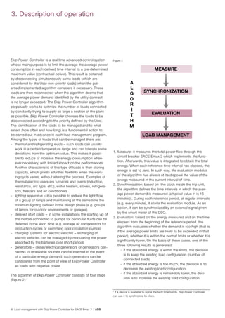
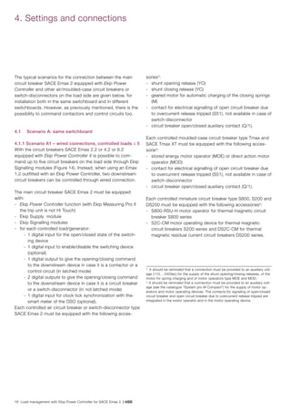
Figure 5
Figure 6
Since Ekip Power Controller is aimed at keeping the total
value of energy in the reference period below the set limit, the
software examines the trend of the curve up to the current
moment and evaluates the energy consumption at the end of
the period, verifying that the ratio between such consumption
and the predefined period does not exceed the contractual
power limit. If this limit is exceeded, the disconnection of one
or more loads is commanded.
Practically the evaluation phase divides the plane t,E in three
zones, indicative of acceptable consumption, high consump-
tion and reduced consumption.
Whenever the evaluation phase is processed, the software
finds the point that describes the current situation and deter-
mines to which of the three zones it corresponds. If the point
falls in the high consumption area, the result of the evaluation
indicates that it is necessary to disconnect one of the loads
and such evaluation is transmitted to the load management
module that chooses which one. The operation described
is performed at regular intervals, every time calculating a
new forecast. In this way, if the forecast of the total power
absorbed by the plant is still too high in spite of the discon-
nection of one load, the algorithm proceeds to disconnect
another load and so on. Then the number of the controlled
loads disconnected and connected varies dynamically, with
the aim of making the power forecast coincide with the target
value.
To describe it, the algorithm tends to “guide” the energy-time
line which represents the energy absorption by the plant as
this line develops from zero (at the initial instant of the refer-
ence period) up to the arrival point (the final instant of the pe-
riod), trying to keep it always within a predefined intermediate
zone (bounded by two curves calculated by the algorithm) by
disconnecting the loads when the line enters the upper zone
or by reconnecting them when the line passes into the lower
one (Figure 6).
2
The most important measure on which Ekip Power Controller is based is the
instantaneous power flowing through the circuit breaker on which it is imple-
mented. The instantaneous power is continuously measured and integrated
during the time to obtain the measure of the energy.
In Figure 6, the thick line (orange) shows the total energy ac-
tually consumed EA
by the plant starting from time t=0.
The disconnection of a load causes a decrease in the slope of
the curve, whereas the reconnection has the opposite effect.
As can be seen, the curve never decreases as time passes (it
would be a horizontal line if there were no power consump-
tion). The dotted lines (EMIN
, EMAX
) represent the boundaries
between the three regions: whenever the curve crosses one of
such boundaries, the algorithm reacts with load connection or
disconnection.
The three zones are not separated by straight lines, but by
curves: these are polynomial curves optimized by the software
according to the number of loads and so as to permit the
consumed power to exceed the maximum allowed level (also
significantly), provided that the total energy consumed in the
period does not risk to exceed the limit (having the average
value of the power lower than the contractual limit).
Therefore if, at a given instant, the power is very high, but for
a short period only, Ekip Power Controller shall not trip. If in-
E [kWh]
t [h]
Ideal Consumption
Target
Ideal Load
Profile
t [h]
E [kWh]
EMIN
EMAX
T
EA](https://image.slidesharecdn.com/eaa889f0-a3cd-46bc-af12-4ed0da8afad3-151022214957-lva1-app6892/85/White-paper-10-320.jpg)

![10 Load management with Ekip Power Controller for SACE Emax 2 | ABB
devices installed in the plant:
- tripping of protection trip units - if one of the controlled
circuit breakers opens due to a protection trip, for safety
reasons (in particular not to reclose on a short-circuit) it
can no longer be managed by the controller as it will be
deemed "not available for control" by the algorithm. It will
remain in this state until the user has reset the breaker and
made it available again. More specifically, if a controlled
circuit breaker is tripped due to the overcurrent release, the
algorithm, after three attempts to issue an opening com-
mand, gives an alarm signal and temporarily excludes that
circuit breaker from the priority list until the trip state has
been reset: the reset operation can be carried out through
local manual command from display or through Ekip Con-
nect remotely.
- manual operation – the loads are considered “not avail-
able” also when the operator acts manually on the relevant
circuit breakers. Such loads will remain in that condition
until reactivation is commanded by the operator.
3. Description of operation
3.1 Example of operating logic
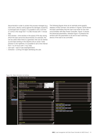
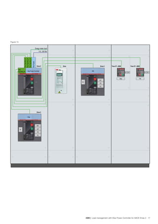
Supposing we have an electrical plant (Figure 7) which con-
sists of three big loads, one priority load (P3
) and two non-
priority ones (P1
and P2
). P1
and P2
can be managed throu-
gh the Ekip Power Controller logic in compliance with the
principle described below. In this example, the time interval of
action of the algorithm is set by the User to 15 minutes.
Figure 7
At the moment the synchronization signal is sent from the
DSO meter, the three loads are all connected with a total
power lower than the limit contractual power (Pc
=1500 kW).
With reference to the diagrams of Figures 8 to 11, at the in-
stant t1 there is a peak of power absorption of load P3
, but its
duration does not exceed the set limit for power demand in 15
minutes (Ea
= Pc
*0.4 [kWh]) according to the evaluation of Ekip
Power Controller algorithm. As a consequence, none of the
non-priority loads is disconnected.
At the instant t2
the power absorption of P3
increases so that
the sum of the three power demands exceeds the contractual
power and with such duration that the result of the algorithm
forecast is a value exceeding the absorbable energy. As a
consequence, Ekip Power Controller disconnects the load P1
,
which comes before P2
in the priority list for disconnection.
The load P2
must stay disconnected for a minimum time t1min_off
(i.e. up to the instant t4
). This minimum time is necessary to
avoid too frequent switching operations which can affect life of
the switching devices and proper load operation.
At t3
the power absorption of P2
increases, but since the sum
of P2
and P3
is lower than the contractual power Pc
the algo-
rithm does not intervene.
At t4
Ekip Power Controller consents to reclose P1
, also be-
cause the load P3
has reduced the absorbed power and there-
fore the total absorption of the three loads is lower than Pc
.
At t5
there is a further increase in the power absorbed by P3
such that the sum of P3
and P2
is already higher than the con-
tractual one and the duration is such that Ekip Power Control-
ler detects the risk of exceeding the absorbable energy.
As a consequence, the algorithm disconnects firstly the load
P1
in t6
(in compliance with the minimum time t1min_on
), but by
evaluating the possibility of exceeding the absorbable energy,
in t7
it disconnects also P2
.
After the minimum times t1min_off
and t2min_off
of P1
and P2
respec-
tively, since the power absorbed by P3
has decreased, the
algorithm reconnects the loads according to their connection
priority (times t1min_off
and t2min_off
permitting) and the operation
logic repeats indefinitely for each time interval defined by the
User.
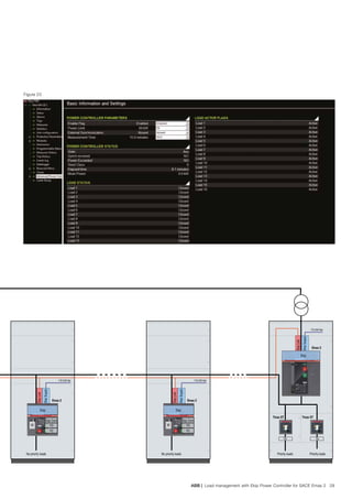
As can be noticed in the diagram which represents the total
load (Figure 11), in the considered interval of 15 minutes there
can be some power absorptions exceeding the contractual
power limit Pc
, but, thanks to the algorithm of Ekip Power
Controller, the average power Pm
absorbed always remains
under the limit contractual power Pc
.
Emax 2
P3P1 P2](https://image.slidesharecdn.com/eaa889f0-a3cd-46bc-af12-4ed0da8afad3-151022214957-lva1-app6892/85/White-paper-12-320.jpg)
![ABB | Load management with Ekip Power Controller for SACE Emax 2 11
Figure 8 - Load P1
Figure 9 - Load P2
Figure 10 - Load P3
Figure 11 - Total load
0 5 10 15
900
t[min]
P[kW]
800
700
600
500
400
300
200
100
0
20 25 30 35 40 45 50
0 5 10 15
600
500
400
300
200
100
0
20 25 30 35 40 45 50
t[min]
P[kW]
0 5 10 15
800
1000
1200
1400
600
400
200
0
20 25 30 35 40 45 50
t[min]
P[kW]
0 5 10 15
1500
2000
2500
3000
1000
500
0
20 25 30 35 40 45 50
t[min]
P[kW]
t1 t2 t3
t4
t5
t7
t6
Average power Pm
Limit contractual power Pc](https://image.slidesharecdn.com/eaa889f0-a3cd-46bc-af12-4ed0da8afad3-151022214957-lva1-app6892/85/White-paper-13-320.jpg)


![30 Load management with Ekip Power Controller for SACE Emax 2 | ABB
5. Application example
The following example illustrates a practical application of
load management in a plant in which Ekip Power Controller
is used to decrease the maximum power demand from the
network and therefore to reduce the contractual power agreed
upon with the DSO with consequent economic savings.
In particular, this example refers to a 4 star air-conditioned
hotel complex, consisting of 80 rooms (20 on each floor), con-
nected to a MV 15 kV network through its own transforma-
tion substation. The complex comprises private underground
parking, swimming pool, wellness center (spa), tennis court
and outdoor parking.
The monthly average consumption is about 150 MWh and a
power factor correction plant is installed to keep the monthly
average power factor equal to or higher than 0.9.
During high season period maximum total power absorption
of about 578 kW has been detected. The following table is the
result of a more detailed analysis of the power demand of the
different types of load:
Rooms 168000
Corridors 3600
Stairs 2880
Hall 4800
Kitchen (electric stoves/ovens, refrigerators,
freezers)
16000
Restaurant 19200
Bar 4200
Elevators 32400
Air-conditioning 208320
Laundry 8400
Swimming pools 32000
Wellness center / Spa 32000
Congress room 14400
Storage rooms and various facilities 9600
Tennis courts (night lighting) 4800
Outdoor lighting 12000
Underground car parking 6000
578600
Table 1 – Power absorbed [W] according to the type of load
Figure 24
100 - 107 108- 115
Various facilities/
Storage rooms
Tennis court Outdoor
lighting
Stairs Elevators Floor 5
Wellness
(Spa)
Swimming
pool
Air conditioning
Floor 4
Corridors Rooms
Floor 3
Air conditioning Corridors RoomsAir conditioning](https://image.slidesharecdn.com/eaa889f0-a3cd-46bc-af12-4ed0da8afad3-151022214957-lva1-app6892/85/White-paper-32-320.jpg)
![ABB | Load management with Ekip Power Controller for SACE Emax 2 31
Therefore, in order to reduce the maximum contractual power
agreed upon with the DSO, through Ekip Power Controller
function the aim is to decrease the maximum power absorp-
tion at 500 kW.
Then, it is the task of Ekip Power Controller function of SACE
Emax 2 to disconnect/reconnect the defined loads in order
not to exceed the contractual power in the hour bands.
The selected loads, which could be disconnected for some
minutes and therefore managed by Ekip Power Controller ac-
cording to the priority list defined by the User, are the follow-
ing:
- air conditioning system considered per floor
- water heating systems and swimming pool circulation pumps
- heating in sauna, turkish bath, hydromassage areas
- electric stoves/ovens
- laundry
- freezers
- refrigerators
- reduction in the lighting of the underground parking and
outdoor.
The main electrical diagram (Figure 24) showing the different
circuit breakers which command/protect the supply lines of
the various loads is given below:
Taking into consideration different countries, Table 2 shows
some examples of the annual savings that can be obtained on
the power quota thanks to Ekip Power Controller function9
.
116- 123 124- 131
Floor 2 Floor 1
Ground floor Floor -1
Kitchen
Freezer Electric
ovens
RestaurantCongress
room
Bar Laundry Car
parking
Hall
Corridors RoomsAir conditioning Corridors RoomsAir conditioning
Air conditioning
Annual costs [€] Annual
savings [€]Contractual power 580 kW 500 kW
Italy 16261.75 14018.75 2243.00
Spain 18513.60 15960.00 2553.60
China 15590.40 13440.00 2150.40
India 17748.00 15300.00 2448.00
Brazil 20949.60 18060.00 2889.60
USA (Wisconsin) 75980.00 65500.00 10480.00
Canada 87278.40 75240 12038.40
Table 2
9
Local currencies have been converted into Euros to express the annual costs.
For a thorough economic analysis on the investment return the various up-to-
date annual savings and the initial costs for equipping the circuit breakers and
for additional wiring should be taken into consideration.](https://image.slidesharecdn.com/eaa889f0-a3cd-46bc-af12-4ed0da8afad3-151022214957-lva1-app6892/85/White-paper-33-320.jpg)