A Novel Rotor Resistance Estimation Technique for Vector Controlled Induction...
Poster
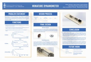
1. Miniature Dynamometer
Chilan Sethuge | Jigme Dorjee | Shariq Shahab
Supervising Professor: Matthew Mackay
Client: University of Toronto - Mechanical Eng. Dept
Problem Statement
Functions
Design Process
Final Design
The University of Toronto is searching for a new technique to increase the
learning experience of engineering students studying machine design for the
first time. The recommended solution by The University of Toronto is to design
and build a compact and flexible miniature dynamometer that is capable of
displaying its results.
It should read the varying output parameters (Rotational Speed and Torque) of
the Machine under Test (MUT).
It should quantify and display the varying parameters to the user in the form of
a RPM vs Torque curve, specific to the motor being tested.
It should simulate the intended operating conditions for the following 3
motors.
Transporting
Rotational
Motion
Sensors
Decoding
Sensor Data Housing
Visual Display
Cooling
RPM Measurement
An encoder wheel coupled with a module is used to measure the rotational speed
of the MUT. The module uses an Infrared (IR) LED to direct IR light towards the
encoder wheel. The frequency of the IR light passing through the encoder wheel
is used to quantify the rotational speed.
Torque Measurement
A sheet of metal, referred to as the Deforming Shaft, is used to measure the
torque applied by the MUT. As torque is transmitted through the system, the
optical sensors measure the relative phase shift between the encoder wheels, as
the shaft elastically deforms. In addition, this deformation is enhanced by a back
driven motor, used to apply a controlled variable load torque at the discretion of
the operator.
Conclusion
Future Work0
50
100
150
200
250
300
AC Motor Speed Torque Curve
100%90%80%70%60%50%40%30%20%10%0%
Torque
Speed
Breakaway Torque Peak Torque
Rated Load Torque
0.0
0.2
0.4
0.6
0.8
1.0
Universal Speed Torque Curve
100%80%60%40%20%0%
Torque
Speed
Torque
Speed
Stall Torque
No Load
0.0
0.2
0.4
0.6
0.8
1.0
DC Motor Speed Torque Curve
100%90%80%70%60%50%40%30%20%10%0%
DC Motor
AC Motor
Universal Motor
The design process yielded complete engineering specifications for an
operating dynamometer, fully equipped with required models, components,
codes, and assembly instructions. A prototype for this dynamometer was
constructed that measured and outputted a corresponding RPM vs. Torque
curve for a given MUT.
However, the prototype has inherent problems that contribute to inaccuracies
through its system. Imperfect machining of assembly holes lead to the
accumulation of tolerances throughout several components of the prototype,
eventually increasing the overall friction experienced by the dynamometer.
In conclusion, the dynamometer is a successful first attempt at producing a
working prototype for the problem. With a few adjustments and additions, this
model can be improved into a fully functional dynamometer able to accurately
measure and display both the RPM and Torque of a variety of electric motors.
Housing
Calibrating
Acrylic or Metal Base
Improve safety for operator
Increase accuracy of prototype
Reduce tolerances between
mounting holes, resulting in
lower friction