SlideShare a Scribd company logo
Porosity
No. Defects Remedies
1. Contamination of work piece Clean joint area.
2. Excessive moisture pickup in electrode covering Store electrodes properly. Follow manufactures recommended rebaking procedure.
3. Moisture of work surfaces Use preheating / warm up work piece.
4. High Sulphur content of base metal Use basic coated electrode.
5. a) Long arc length
b) Excessive current
c) Higher travel speed
Change welding parameters and technique.
Use preheat
6. High solidification rate Increase heat input.
Inclusions
No
.
Defects Remedies
1. Improper cleaning procedure Clean work surfaces and each weld run thoroughly. Wherever necessary use power wire brush, grinders, chisels to
ensure a through removal of slag.
2. Improper welding technique
a) Excessive weaving
b) High travel speed
c) Slag flooding ahead of welding arc.
Improve welding technique
Reposition work to prevent loss of slag control wherever possible.
Restrict weaving to a minimum.
3. Narrow, inaccessible joints Increase groove angle.
Incomplete Fusion
No
.
Defects Remedies
1. Improper joint design Increase included angle of groove joint. Change the groove design to a ‘J’ or a ‘U’ type.
2. Presence of slag or oxide flim Clean weld surfaces prior to welding
3. Incorrect electrode position and operation
current
Maintain proper electrode position and current
4. Improper manipulation of arc Use correct manipulation techniques to melt the joint faces properly.
Inadequate Penetration
No
.
Defects Remedies
1. Improper Joint preparation
a) Excessively thick root face
b) Insufficient root opening
c) Bridging of root opening
Use proper joint geometry.
Reduce root face height.
Use wider root opening.
2. Electrode diameter too large Use smaller electrode in root.
3. Inadequate current Follow correct welding current and technique
Cracks
No
.
Defects Remedies
1. High rigidity of joint Use preheating
Relieve residual stresses.
Minimize shrinkage stresses, Using back step or block
welding sequences.
2. Poor Joint fit up Adjust root opening all alignment
3. Higher carbon content of weld metal and / or
harden able base material/
Use proper electrode
Use buttering layers wherever necessary
4. Too Small a weld bead Decrease travel speed to increase cross section of bead.
5. High Sulphur content in base or Use filler with high level of weld metal sulphur fixing element like Mn.
6. Hot cracking Reduce the heat input.
7. Cracking at the crater Filling up the crator before withdrawing the electrode
Use taper power control device.
Use back step welding technique
8. Higher harden ability Preheat the job.
Post weld heat treatment without cooling to room temperature.
9. Hydrogen induced cracking /Delayed cracking Use low Hydrogen welding electrode
Use suitable preheat and post Weld heat treatment
10. Presence of brittle phases in the Micro
structure of the base Material
Soften the material before welding.
11. Low ductility of the base material Use preheat.
Anneal the base metal
Use ductile weld metal.
12. High residual stresses Redesign the weld metal and reduce restraints
Change welding sequence
Use intermediate stress-relief Heat treatment.
13. Excessive dilution Change welding current.
Use buttering technique wherever possible.
14. Under Cut Reduce Current
Use proper diameter of Electrode
Reduce weaving
15. Spatter Reduce Current
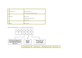
AWS CLASSIFICATION SFA 5.1 - A FOUR OR A FIVE DIGIT CODING
AWS Classification Type of covering Welding Position Type of current
E 6010 High cellulose sodium F,V,OH,H DC(+)
E 6011 High cellulose potassium F,V,OH,H AC/DC(+)
E 6012 High titania sodium F,V,OH,H AC/DC(-)
E 6013 High titania potassium F,V,OH,H AC/DC
E 6020 High iron oxide F,V,OH,H AC/DC(-)
E 6027 High iron oxide iron powder AC/DC(-)
E 7014 Iron powder, titania AC/DC
E 7015 Low hydrogen Sodium F,V,OH,H DC
E 7016 Low hydrogen potassium F,V,OH,H AC/DC(+)
E 7018 Low hydrogen Potassium F,V,OH,H AC/DC (+)
Iron powder
E 7018 M Low hydrogen iron powder F,V,OH,H DC+
E 7024 Iron powder, titania H-fillets, F AC/DC
E 7027 High iron oxide, iron powder H-fillets,F AC/DC(-)
E 7028 Low hydrogen potassium H-fillets, F AC/DC (+)
Iron powder
E 7048 Low hydrogen potassium F,V,OH,H AC/DC/(+)
Iron powder V-down
1.
 Transverse
 Crater
 Throat
 Toe
 Root
 Cold or delayed
 Underbead and Heat-affected zone
 Hot
o Misalignment (hi-lo)
o Undercut
o Underfill
o Concavity or Convexity
o Excessive reinforcement
o Improper reinforcement
o Overlap
o Burn-through
o Incomplete or Insufficient Penetration
o Incomplete Fusion
o Surface irregularity
 Overlap
o Arc Strikes
o Base Metal Discontinuities
 Lamellar tearing
 Laminations and Delaminations
 Laps and Seams
o Porosity
 Uniformly Scattered
 Cluster
 Linear
 Piping
o Heat-affected zone microstructure alteration
o Base Plate laminations
o Size or dimensions
2. Misalignment (hi-lo)
o Definition: Amount a joint is out of alignment at the root
o Cause: Carelessness. Also due to joining different thicknesses (transition thickness)
o Prevention: Workmanship. Transition angles not to exceed 2.5 to 1.
o Repair: Grinding. Careful on surface finish and direction of grind marks. Inside of Pipe /Tube difficult.
3. Misalignment
4. Undercut
o Definition: A groove cut at the toe of the weld and left unfilled.
o Cause: High amperage, electrode angle, long arc length, rust
o Prevention: Set machine on scrap metal to correct parameters. Clean metal before welding.
o Repair: Weld with smaller electrode, sometimes must be low hydrogen with preheat. Sometimes must gouge first.
5. Undercut
o Undercut typically has an allowable limit. Different codes and standards vary greatly in the allowable amount.
o Plate - the lesser of 0.8mm or 5% (norm)
o ESC EN BS288 allows up to 1mm anything deeper than this must be repaired!
6. Under Cut
7. Insufficient Fill or Under fill
o Definition: The weld surface is below the adjacent surfaces of the base metal
o Cause: Improper welding techniques
o Prevention: Apply proper welding techniques for the weld type and position. Use stripper beads before the cover pass.
o Repair: Simply weld to fill. May require preparation by grinding.
8. Under fill
9. Insufficient Fill on the Root Side (suckback)
o Definition: The weld surface is below the adjacent surfaces of the base metal at the weld root.
o Cause: Typically improper joint preparation or excessive weld pool heat.
o Prevention: Correct cause. (see next slide)
o Repair: Backweld to fill. May requireremoval of weld section by grinding for access to the joint root.
10. Cause for Insufficient Fill at the Root Some liquids, like water or molten steel, try to cover as much surface area of whatever they are in contact with as possible.
Welding a root pass too wide can also cause the bead to sag (overhead position).
11.
12.
13. Removing a root pass by grinding 1. Recreate the groove geometry as closely as possible. 2. Use a saw or die grinder and 1/16 - 1/8” cut off wheel to recreate root
opening. Remember repairs are sometimes required to be made with a smaller electrode. 3. Open the groove angle. Be careful to leave the proper root face dimension. 4.
Feather the start and stop to blend smoothly into and out of the existing weld.
14.
15. Excessive Concavity or Convexity
o Definition: Concavity or convexity of a fillet weld which exceeds the specified allowable limits
o Cause: Amperage and travel speed
o Prevention: Observe proper parameters and techniques.
o Repair: Grind off or weld on. Must blend smoothly into the base metal.
16. Concavity
17. Root Concavity
18. Convexity
19. Reinforcement
o Excessive
o Insufficient
o Improper contour
The amount of a groove weld which extends beyond the surface of the plate Face Reinforcement Root Reinforcement
20. Excessive Reinforcement
o Definition: Specifically defined by the standard. Typically, Reinforcement should be flush to 1/16”(pipe) or flush to 1/8” (plate or structural shapes).
o Cause: Travel speed too slow, amperage too low
o Prevention: Set amperage and travel speed on scrap plate.
o Repair: Remove excessive reinforcement and feather the weld toes to a smooth transition to the base plate.
21. Excessive Penetration
22.
o Definition: Specifically defined by the standard. Typically, Underfill may be up to 5% of metal thickness not to exceed 1/32” as long as the thickness is
made up in the opposite reinforcement. Not applied to fillet welds.
o Cause: On root reinforcement - Too little filler metal will cause thinning of the filler metal. In OH position, too hot or too wide will cause drooping of the
open root puddle.
o Prevention: Use proper welding technique. Use backing or consumable inserts. Use back weld or backing.
o Repair: Possibly simply increase the face reinforcement. If backwelding is not possible, must remove and reweld.
Insufficient Reinforcement
23.
o Definition: When the weld exhibits less than a 135 0 transition angle at the weld toe.
o Cause: Poor welding technique
o Prevention: Use proper techniques. A weave or whip motion can often eliminate the problem.
o Repair: The weld face must be feathered into the base plate.
135 0 Improper Weld Contour
24. Overlap
o Definition: When the face of the weld extends beyond the toe of the weld
o Cause: Improper welding technique. Typically, electrode angles and travel speed.
o Prevention: Overlap is a contour problem. Proper welding technique will prevent this problem.
o Repair: Overlap must be removed to blend smoothly into the base metal. Be careful of deep grind marks that run transverse to the load. Also be careful of
fusion discontinuities hidden by grinding. Use NDT to be sure.
25. Overlap Overlap is measured with a square edge such as a 6” rule. No amount of overlap is typically allowed.
26. Burn-through (non-standard)
o Definition: When an undesirable open hole has been completely melted through the base metal. The hole may or may not be left open.
o Cause: Excessive heat input.
o Prevention: Reduce heat input by increasing travel speed, use of a heat sink, or by reducing welding parameters.
o Repair: Will be defined by standards. Filling may suffice. Otherwise, removal and rewelding may be required. Some standards may require special filler
metal and/or PWHT.
27. Incomplete or Insufficient Penetration
o Definition: When the weld metal does not extend to the required depth into the joint root
o Cause: Low amperage, low preheat, tight root opening, fast travel speed, short arc length.
o Prevention: Correct the contributing factor(s).
o Repair: Back gouge and back weld or remove and reweld.
28. ICP
29. Incomplete Fusion
o Definition: Where weld metal does not form a cohesive bond with the base metal.
o Cause: Low amperage, steep electrode angles, fast travel speed, short arc gap, lack of preheat, electrode too small, unclean base metal, arc off seam.
o Prevention: Eliminate the potential causes.
o Repair: remove and reweld, being careful to completely remove the defective area. This is sometimes extremely difficult to find.
30. Lack of Side Wall Fusion
31. Arc Strike
o Definition: A localized coalescence outside the weld zone.
o Cause: Carelessness
o Prevention: In difficult areas, adjacent areas can be protected using fire blankets.
o Repair: Where applicable, arc strikes must be sanded smooth and tested for cracks. If found, they must be remove and repaired using a qualified repair
procedure and inspected as any other weld.
32. Arc Strike
33. Weld Spatter Causes Prevention High arc power Reduce arc power Magnetic arc blow Reduce arc length or switch to AC power Incorrect settings for GMAW process
Modify electrical settings (but be careful to maintain full fusion Damp electrodes Use dry electrodes
34. Inclusions
o Slag
o Wagontracks
o Tungsten
35.
o Definition: Slag entrapped within the weld
o Cause: Low amperage, improper technique, Trying to weld in an area that is too tight. Slow travel in Vertical Down
o Prevention: Increase amperage or preheat, grind out tight areas to gain access to bottom of joint.
o Repair: Remove by grinding. Reweld.
Slag Inclusion
36. Slag Inclusion
37.
o Definition: Slang term for a groove left at the toe of a root pass which becomes filled with slag and is trapped in the weld.
o Cause: The contour of the root pass is too high, or the weld toe is not bonded to the base metal
o Prevention: Use proper technique to deposit the weld root.
o Repair: Best repaired before applying the hot pass. Carefully grind the root pass face flat. be careful not to gouge other areas on the weldment.
Wagon Tracks (non-standard)
38.
o Definition: A tungsten particle embedded in a weld. (Typically GTAW only)
o Cause: Tungsten electrode too small, amperage too high, AC balance on +, Upslope too high, electrode tip not snipped, electrode dipped into the weld
pool or touched with the fill rod, electrode split.
o Prevention: Eliminate the cause
o Repair: Grind out and reweld
Tungsten Inclusion
39. Inclusions
o fix when you see it. otherwise grind out & fix
40. Whiskers
o Unsightly
o Inhibits material flow in piping
o Are inclusions
o Can break off in pipes and damage equipment downline
41. Spatter
o Definition: Small particles of weld metal expelled from the welding operation which adhere to the base metal surface.
o Cause: Long arc length, severe electrode angles, high amperages.
o Prevention: Correct the cause. Base metal can be protected with coverings or hi-temp paints.
o Repair: Remove by grinding or sanding. Sometimes must be tested as if it were a weld.
42. Arc Craters
o Definition: A depression left at the termination of the weld where the weld pool is left unfilled.
o Cause: Improper weld termination techniques
o Prevention:
o Repair: If no cracks exist, simply fill in the crater. Generally welding from beyond the crater back into the crater.
43. Cracks
o Longitudinal
o Transverse
o Crater
o Throat
o Toe
o Root
o Underbead and Heat-affected zone
o Hot
o Cold or delayed
44.
o Definition: A crack running in the direction of the weld axis. May be found in the weld or base metal.
o Cause: Preheat or fast cooling problem. Also caused by shrinkage stresses in high constraint areas.
o Prevention: Weld toward areas of less constraint. Also preheat to even out the cooling rates.
o Repair: Remove and reweld
Longitudinal Crack
45.
o Definition: A crack running into or inside a weld, transverse to the weld axis direction.
o Cause: Weld metal hardness problem
o Prevention: Minimize heat input and monitor interpass temperature max 200 c
o Repair: Dependant on specification and matterial
Transverse Crack
46.
o Definition: A crack, generally in the shape of an “X” which is found in a crater. Crater cracks are hot cracks.
o Cause: The center of the weld pool becomes solid before the outside of the weld pool, pulling the center apart during cooling
o Prevention: Use crater fill, fill the crater at weld termination and/or preheat to even out the cooling of the puddle
o Repair:
Crater Crack
47.
o Definition: A longitudinal crack located in the weld throat area.
o Cause: Transverse Stresses, probably from shrinkage. Indicates inadequate filler metal selection or welding procedure. May be due to crater crack
propagation.
o Prevention: Correct initial cause. Increasing preheat may prevent it. be sure not to leave a crater. Use a more ductile filler material.
o Repair: Remove and reweld using appropriate procedure. Be sure to correct initial problem first.
Throat Crack
48.
o Definition: A crack in the base metal beginning at the toe of the weld
o Cause: Transverse shrinkage stresses. Indicates a HAZ brittleness problem.
o Prevention: Increase preheat if possible, or use a more ductile filler material.
o Repair:
Toe Crack
49. Toe Crack
50.
o Definition: A crack in the weld at the weld root.
o Cause: Transverse shrinkage stresses. Same as a throat crack.
o Prevention: Same as a throat crack
o Repair:
Root Crack
51. Root Crack
52.
o Definition: A crack in the unmelted parent metal of the HAZ.
o Cause: Hydrogen embrittlement
o Prevention: Use Lo/Hi electrodes and/or preheat
o Repair: (only found using NDT). Remove and reweld.
Underbead Crack
53.
o Definition: A crack in the weld that occurs during solidification.
o Cause: Micro stresses from weld metal shrinkage pulling apart weld metal as it cools from liquid to solid temp.
o Prevention: Preheat or use a low tensil filler material.
o Repair:
Hot Crack
54.
o Definition: A crack that occurs after the metal has completely solidified
o Cause: Shrinkage, Highly restrained welds, Discontinuities
o Prevention: Preheat, weld toward areas of less constraint, use a more ductile weld metal
o Repair: Remove and reweld, correct problem first, preheat may be necessary.
Cold Crack
55. Cold Crack or Weld Metal Hydrogen Crack
56. Repairs to Cracks
o Determine the cause
o Correct the problem
o Take precautions to prevent reoccurrence
o Generally required to repair using a smaller electrode
57. Base Metal Discontinuities
o Lamellar tearing
o Laminations and Delaminations
o Laps and Seams
58. Lamellar Tearing
59. Laminations
o Base Metal Discontinuity
o May require repair prior to welding
o Formed during the milling process
60. Lamination effects can be reduced by joint design:
61. Laps and Seams A mill-induced discontinuity in which results from a lump of metal being squeezed over into the surface of the material. If beyond acceptable limits,
must be removed and repaired or discarded.
62. Porosity
o Single Pore
o Uniformly Scattered
o Cluster
o Linear
o Piping
63. Porosity
64. Single Pore
o Separated by at least their own diameter along the axis of the weld
65. Uniformly Scattered Porosity
o Typically judged by diameter and proximity to a start or stop
o often caused by low amperage or short arc gap or an unshielded weld start
66. Cluster Porosity
o Typically viewed as a single large discontinuity
67. Linear Porosity
o being linear greatly affects the severity of this discontinuity
68. Piping Porosity
o Generally has special allowable limits
69. Porosity
o preheat will help eliminate
o may need an electrode with more deoxidizers
o Use run-on/run-off taps
o restart on top of previous weld and grind off lump
70. Heat-affected zone microstructure alteration
o add drawing of HAZ of groove weld with leaders to:
 grain refinement
 grain growth
 hardened areas
 softened areas
 precipitate suseptable areas.
71. Size or dimension
o If it renders the part unusable, it is a defect.
o If it is outside the allowable limit, it renders the part unusable.
o Things don’t have to be perfect, just within the acceptable tolerance. Working to perfection is too time consuming and costly
72. Hammer marks
o Stress risers
o Unsightly
o Unnecessary
73. REPAIR TECHNIQUES
o May involve:
 different process
 different procedure
 different preheat/PWHT
 different electrode
 smaller electrode
74. Only repair defects. Discontinuities are by definition acceptable. Repair is therefore unnecessary and not cost effective.

More Related Content

What's hot

Welding Inspection
Welding InspectionWelding Inspection
Welding Inspection
Randall Stremmel
 
Weld repair raghav
Weld repair raghavWeld repair raghav
Welding technology
Welding  technologyWelding  technology
Welding technology
PRABIR DATTA
 
Defects in Materials
Defects in MaterialsDefects in Materials
Defects in Materials
Sirat Mahmood
 
9488085 welding-defects
9488085 welding-defects9488085 welding-defects
9488085 welding-defects
Rony Simeon
 
Cswip welding inspection notes and questions
Cswip welding inspection notes and questionsCswip welding inspection notes and questions
Cswip welding inspection notes and questions
Karthik Banari
 
Weld discountinuitie
Weld discountinuitieWeld discountinuitie
Weld discountinuitie
Jithu John
 
Wis5 welding defects 02
Wis5 welding defects 02Wis5 welding defects 02
Wis5 welding defects 02
Thang Do Minh
 
Weld defects, causes, and remedies
Weld defects, causes, and remediesWeld defects, causes, and remedies
Weld defects, causes, and remedies
emmanyoung
 
Welding defects
Welding defectsWelding defects
Welding defects
rammahalle
 
000043
000043000043
000043
Dantoy14
 
Welding Defects
Welding Defects Welding Defects
Welding Defects
wishmikakavindukahat
 
CSWIP Intro
CSWIP IntroCSWIP Intro
CSWIP Intro
Imran Jamil
 
Weld defects and discontinuities
Weld defects and discontinuitiesWeld defects and discontinuities
Weld defects and discontinuities
Nima Tajallipour
 
Causes and Remedies for Porosity during Welding
Causes and Remedies for Porosity during WeldingCauses and Remedies for Porosity during Welding
Causes and Remedies for Porosity during Welding
Vignesh kumar
 
Presentation on common weld dicontinuities
Presentation on common weld dicontinuitiesPresentation on common weld dicontinuities
Presentation on common weld dicontinuities
abdul khaliq siddiqui
 
Welding of pipelines
Welding of pipelinesWelding of pipelines
Welding of pipelines
kannanrajagopal
 
Me 328 welding metallurgy
Me 328 welding metallurgyMe 328 welding metallurgy
Me 328 welding metallurgy
Reandy Risky
 
Weld Defects
Weld DefectsWeld Defects
Weld Defects
adminn2
 
16 wis5 consumable
16 wis5 consumable16 wis5 consumable
16 wis5 consumable
Tori Tom
 

What's hot (20)

Welding Inspection
Welding InspectionWelding Inspection
Welding Inspection
 
Weld repair raghav
Weld repair raghavWeld repair raghav
Weld repair raghav
 
Welding technology
Welding  technologyWelding  technology
Welding technology
 
Defects in Materials
Defects in MaterialsDefects in Materials
Defects in Materials
 
9488085 welding-defects
9488085 welding-defects9488085 welding-defects
9488085 welding-defects
 
Cswip welding inspection notes and questions
Cswip welding inspection notes and questionsCswip welding inspection notes and questions
Cswip welding inspection notes and questions
 
Weld discountinuitie
Weld discountinuitieWeld discountinuitie
Weld discountinuitie
 
Wis5 welding defects 02
Wis5 welding defects 02Wis5 welding defects 02
Wis5 welding defects 02
 
Weld defects, causes, and remedies
Weld defects, causes, and remediesWeld defects, causes, and remedies
Weld defects, causes, and remedies
 
Welding defects
Welding defectsWelding defects
Welding defects
 
000043
000043000043
000043
 
Welding Defects
Welding Defects Welding Defects
Welding Defects
 
CSWIP Intro
CSWIP IntroCSWIP Intro
CSWIP Intro
 
Weld defects and discontinuities
Weld defects and discontinuitiesWeld defects and discontinuities
Weld defects and discontinuities
 
Causes and Remedies for Porosity during Welding
Causes and Remedies for Porosity during WeldingCauses and Remedies for Porosity during Welding
Causes and Remedies for Porosity during Welding
 
Presentation on common weld dicontinuities
Presentation on common weld dicontinuitiesPresentation on common weld dicontinuities
Presentation on common weld dicontinuities
 
Welding of pipelines
Welding of pipelinesWelding of pipelines
Welding of pipelines
 
Me 328 welding metallurgy
Me 328 welding metallurgyMe 328 welding metallurgy
Me 328 welding metallurgy
 
Weld Defects
Weld DefectsWeld Defects
Weld Defects
 
16 wis5 consumable
16 wis5 consumable16 wis5 consumable
16 wis5 consumable
 

Viewers also liked

PICTURES-SASOL-RLL1-LRC-KP795-RLL1-NOV-DEC-16
PICTURES-SASOL-RLL1-LRC-KP795-RLL1-NOV-DEC-16PICTURES-SASOL-RLL1-LRC-KP795-RLL1-NOV-DEC-16
PICTURES-SASOL-RLL1-LRC-KP795-RLL1-NOV-DEC-16
Edmond GOUGNARD
 
Arc Welding
Arc WeldingArc Welding
Arc Welding
sonia4v
 
Impact of metals
Impact of metalsImpact of metals
Impact of metals
PPThelperkid
 
Subsea Hyperbaric Welding for Pipeline Repair
Subsea Hyperbaric Welding for Pipeline RepairSubsea Hyperbaric Welding for Pipeline Repair
Subsea Hyperbaric Welding for Pipeline Repair
Neil Woodward
 
Cbc shielded metal arc welding nc ii
Cbc   shielded metal arc welding nc iiCbc   shielded metal arc welding nc ii
Cbc shielded metal arc welding nc ii
Lennard Charles
 
arc_welding_safety[1]
arc_welding_safety[1]arc_welding_safety[1]
arc_welding_safety[1]
HARSHAL KHODE
 
Weldingintro
WeldingintroWeldingintro
Weldingintro
kellykay08
 
introduction to engg materials
introduction to engg materialsintroduction to engg materials
introduction to engg materials
Ravish Roy
 
Arc Welding
Arc WeldingArc Welding
Arc Welding
Ankit Kumar
 
Welded Ship failures
Welded Ship failuresWelded Ship failures
Welded Ship failures
Jasper Graham-Jones
 
Manufacturing Practice 2
Manufacturing Practice 2Manufacturing Practice 2
Manufacturing Practice 2
syfadillahabu
 
1499 methods for charpy impact test
1499 methods for charpy impact test1499 methods for charpy impact test
1499 methods for charpy impact test
Subhraprakash Mondal
 
Important of engg materials
Important of engg materialsImportant of engg materials
Important of engg materials
Tanuj Parikh
 
TESTING OF THE MATERIALS
TESTING OF THE MATERIALSTESTING OF THE MATERIALS
TESTING OF THE MATERIALS
AMIT KUMAR
 
Safety note
Safety noteSafety note
Safety note
Mansoor Shar
 
1080093 634446814277798750
1080093 6344468142777987501080093 634446814277798750
1080093 634446814277798750
Tanuj Parikh
 
Seminr1
Seminr1Seminr1
Seminr1
riteshchandr
 
Safety Notes: Manual Metal Arc Welding
Safety Notes: Manual Metal Arc WeldingSafety Notes: Manual Metal Arc Welding
Safety Notes: Manual Metal Arc Welding
Jo Kay
 
Manual metal arc welding
Manual metal arc weldingManual metal arc welding
Manual metal arc welding
johnmcnelly
 
Arc welding & safty
Arc welding & saftyArc welding & safty
Arc welding & safty
illpa
 

Viewers also liked (20)

PICTURES-SASOL-RLL1-LRC-KP795-RLL1-NOV-DEC-16
PICTURES-SASOL-RLL1-LRC-KP795-RLL1-NOV-DEC-16PICTURES-SASOL-RLL1-LRC-KP795-RLL1-NOV-DEC-16
PICTURES-SASOL-RLL1-LRC-KP795-RLL1-NOV-DEC-16
 
Arc Welding
Arc WeldingArc Welding
Arc Welding
 
Impact of metals
Impact of metalsImpact of metals
Impact of metals
 
Subsea Hyperbaric Welding for Pipeline Repair
Subsea Hyperbaric Welding for Pipeline RepairSubsea Hyperbaric Welding for Pipeline Repair
Subsea Hyperbaric Welding for Pipeline Repair
 
Cbc shielded metal arc welding nc ii
Cbc   shielded metal arc welding nc iiCbc   shielded metal arc welding nc ii
Cbc shielded metal arc welding nc ii
 
arc_welding_safety[1]
arc_welding_safety[1]arc_welding_safety[1]
arc_welding_safety[1]
 
Weldingintro
WeldingintroWeldingintro
Weldingintro
 
introduction to engg materials
introduction to engg materialsintroduction to engg materials
introduction to engg materials
 
Arc Welding
Arc WeldingArc Welding
Arc Welding
 
Welded Ship failures
Welded Ship failuresWelded Ship failures
Welded Ship failures
 
Manufacturing Practice 2
Manufacturing Practice 2Manufacturing Practice 2
Manufacturing Practice 2
 
1499 methods for charpy impact test
1499 methods for charpy impact test1499 methods for charpy impact test
1499 methods for charpy impact test
 
Important of engg materials
Important of engg materialsImportant of engg materials
Important of engg materials
 
TESTING OF THE MATERIALS
TESTING OF THE MATERIALSTESTING OF THE MATERIALS
TESTING OF THE MATERIALS
 
Safety note
Safety noteSafety note
Safety note
 
1080093 634446814277798750
1080093 6344468142777987501080093 634446814277798750
1080093 634446814277798750
 
Seminr1
Seminr1Seminr1
Seminr1
 
Safety Notes: Manual Metal Arc Welding
Safety Notes: Manual Metal Arc WeldingSafety Notes: Manual Metal Arc Welding
Safety Notes: Manual Metal Arc Welding
 
Manual metal arc welding
Manual metal arc weldingManual metal arc welding
Manual metal arc welding
 
Arc welding & safty
Arc welding & saftyArc welding & safty
Arc welding & safty
 

Similar to Welding

Welding Defects (1).ppt
Welding Defects (1).pptWelding Defects (1).ppt
Welding Defects (1).ppt
vipinverma125286
 
welding defects observed during the welding
welding defects observed during the weldingwelding defects observed during the welding
welding defects observed during the welding
MuhammadUzairLiaqat
 
10Defects 1 DEMO.ppt
10Defects 1 DEMO.ppt10Defects 1 DEMO.ppt
10Defects 1 DEMO.ppt
GemDL
 
review-grade-11-3rd-quarter.pptx
review-grade-11-3rd-quarter.pptxreview-grade-11-3rd-quarter.pptx
review-grade-11-3rd-quarter.pptx
NorMayJeanHinayas1
 
WELD DEFECTS.pptx
WELD DEFECTS.pptxWELD DEFECTS.pptx
WELD DEFECTS.pptx
GemDL
 
WELDING DEFECTS
WELDING DEFECTSWELDING DEFECTS
Welding defects
Welding defectsWelding defects
Welding defects
premkumar1862
 
dokumen.tips_5-weld-defect-repair.ppt
dokumen.tips_5-weld-defect-repair.pptdokumen.tips_5-weld-defect-repair.ppt
dokumen.tips_5-weld-defect-repair.ppt
StevenConda2
 
Welded connections in steel structures - Limit State Design of Steel Structures
Welded connections in steel structures - Limit State Design of Steel StructuresWelded connections in steel structures - Limit State Design of Steel Structures
Welded connections in steel structures - Limit State Design of Steel Structures
AshishVivekSukh
 
Weld 1 (nx power lite) (nxpowerlite) (nxpowerlite)
Weld 1 (nx power lite) (nxpowerlite) (nxpowerlite)Weld 1 (nx power lite) (nxpowerlite) (nxpowerlite)
Weld 1 (nx power lite) (nxpowerlite) (nxpowerlite)
Jitesh Gaurav
 
2004_0619CA
2004_0619CA2004_0619CA
2004_0619CA
TRIC Tools
 
Soldering procedures/ orthodontic assistant training
Soldering procedures/ orthodontic assistant trainingSoldering procedures/ orthodontic assistant training
Soldering procedures/ orthodontic assistant training
Indian dental academy
 
Arc Welding process (Smaw)
Arc Welding process (Smaw)Arc Welding process (Smaw)
Arc Welding process (Smaw)
SelvaGovi
 
Welding 1
Welding   1Welding   1
Welding 1
Jithu John
 
Field Service: Problem Resolution - Feb. 2010
Field Service: Problem Resolution - Feb. 2010Field Service: Problem Resolution - Feb. 2010
Field Service: Problem Resolution - Feb. 2010
Piping Technology & Products, Inc.
 
Welding
WeldingWelding
Welding
Manoj Kumar
 
9 003
9 0039 003
9 003
yueke
 
Casting defects
Casting defectsCasting defects
Casting defects
Gulfam Hussain
 
Casting defects
Casting defectsCasting defects
Casting defects
Gulfam Hussain
 
Lead free
Lead freeLead free
Lead free
Irfan Hafeez
 

Similar to Welding (20)

Welding Defects (1).ppt
Welding Defects (1).pptWelding Defects (1).ppt
Welding Defects (1).ppt
 
welding defects observed during the welding
welding defects observed during the weldingwelding defects observed during the welding
welding defects observed during the welding
 
10Defects 1 DEMO.ppt
10Defects 1 DEMO.ppt10Defects 1 DEMO.ppt
10Defects 1 DEMO.ppt
 
review-grade-11-3rd-quarter.pptx
review-grade-11-3rd-quarter.pptxreview-grade-11-3rd-quarter.pptx
review-grade-11-3rd-quarter.pptx
 
WELD DEFECTS.pptx
WELD DEFECTS.pptxWELD DEFECTS.pptx
WELD DEFECTS.pptx
 
WELDING DEFECTS
WELDING DEFECTSWELDING DEFECTS
WELDING DEFECTS
 
Welding defects
Welding defectsWelding defects
Welding defects
 
dokumen.tips_5-weld-defect-repair.ppt
dokumen.tips_5-weld-defect-repair.pptdokumen.tips_5-weld-defect-repair.ppt
dokumen.tips_5-weld-defect-repair.ppt
 
Welded connections in steel structures - Limit State Design of Steel Structures
Welded connections in steel structures - Limit State Design of Steel StructuresWelded connections in steel structures - Limit State Design of Steel Structures
Welded connections in steel structures - Limit State Design of Steel Structures
 
Weld 1 (nx power lite) (nxpowerlite) (nxpowerlite)
Weld 1 (nx power lite) (nxpowerlite) (nxpowerlite)Weld 1 (nx power lite) (nxpowerlite) (nxpowerlite)
Weld 1 (nx power lite) (nxpowerlite) (nxpowerlite)
 
2004_0619CA
2004_0619CA2004_0619CA
2004_0619CA
 
Soldering procedures/ orthodontic assistant training
Soldering procedures/ orthodontic assistant trainingSoldering procedures/ orthodontic assistant training
Soldering procedures/ orthodontic assistant training
 
Arc Welding process (Smaw)
Arc Welding process (Smaw)Arc Welding process (Smaw)
Arc Welding process (Smaw)
 
Welding 1
Welding   1Welding   1
Welding 1
 
Field Service: Problem Resolution - Feb. 2010
Field Service: Problem Resolution - Feb. 2010Field Service: Problem Resolution - Feb. 2010
Field Service: Problem Resolution - Feb. 2010
 
Welding
WeldingWelding
Welding
 
9 003
9 0039 003
9 003
 
Casting defects
Casting defectsCasting defects
Casting defects
 
Casting defects
Casting defectsCasting defects
Casting defects
 
Lead free
Lead freeLead free
Lead free
 

Welding

  • 1. Porosity No. Defects Remedies 1. Contamination of work piece Clean joint area. 2. Excessive moisture pickup in electrode covering Store electrodes properly. Follow manufactures recommended rebaking procedure. 3. Moisture of work surfaces Use preheating / warm up work piece. 4. High Sulphur content of base metal Use basic coated electrode. 5. a) Long arc length b) Excessive current c) Higher travel speed Change welding parameters and technique. Use preheat 6. High solidification rate Increase heat input. Inclusions
  • 2. No . Defects Remedies 1. Improper cleaning procedure Clean work surfaces and each weld run thoroughly. Wherever necessary use power wire brush, grinders, chisels to ensure a through removal of slag. 2. Improper welding technique a) Excessive weaving b) High travel speed c) Slag flooding ahead of welding arc. Improve welding technique Reposition work to prevent loss of slag control wherever possible. Restrict weaving to a minimum. 3. Narrow, inaccessible joints Increase groove angle. Incomplete Fusion No . Defects Remedies 1. Improper joint design Increase included angle of groove joint. Change the groove design to a ‘J’ or a ‘U’ type.
  • 3. 2. Presence of slag or oxide flim Clean weld surfaces prior to welding 3. Incorrect electrode position and operation current Maintain proper electrode position and current 4. Improper manipulation of arc Use correct manipulation techniques to melt the joint faces properly. Inadequate Penetration No . Defects Remedies 1. Improper Joint preparation a) Excessively thick root face b) Insufficient root opening c) Bridging of root opening Use proper joint geometry. Reduce root face height. Use wider root opening. 2. Electrode diameter too large Use smaller electrode in root. 3. Inadequate current Follow correct welding current and technique
  • 4. Cracks No . Defects Remedies 1. High rigidity of joint Use preheating Relieve residual stresses. Minimize shrinkage stresses, Using back step or block welding sequences. 2. Poor Joint fit up Adjust root opening all alignment 3. Higher carbon content of weld metal and / or harden able base material/ Use proper electrode Use buttering layers wherever necessary 4. Too Small a weld bead Decrease travel speed to increase cross section of bead. 5. High Sulphur content in base or Use filler with high level of weld metal sulphur fixing element like Mn.
  • 5. 6. Hot cracking Reduce the heat input. 7. Cracking at the crater Filling up the crator before withdrawing the electrode Use taper power control device. Use back step welding technique 8. Higher harden ability Preheat the job. Post weld heat treatment without cooling to room temperature. 9. Hydrogen induced cracking /Delayed cracking Use low Hydrogen welding electrode Use suitable preheat and post Weld heat treatment 10. Presence of brittle phases in the Micro structure of the base Material Soften the material before welding. 11. Low ductility of the base material Use preheat. Anneal the base metal Use ductile weld metal. 12. High residual stresses Redesign the weld metal and reduce restraints Change welding sequence Use intermediate stress-relief Heat treatment.
  • 6. 13. Excessive dilution Change welding current. Use buttering technique wherever possible. 14. Under Cut Reduce Current Use proper diameter of Electrode Reduce weaving 15. Spatter Reduce Current AWS CLASSIFICATION SFA 5.1 - A FOUR OR A FIVE DIGIT CODING AWS Classification Type of covering Welding Position Type of current
  • 7. E 6010 High cellulose sodium F,V,OH,H DC(+) E 6011 High cellulose potassium F,V,OH,H AC/DC(+) E 6012 High titania sodium F,V,OH,H AC/DC(-) E 6013 High titania potassium F,V,OH,H AC/DC E 6020 High iron oxide F,V,OH,H AC/DC(-) E 6027 High iron oxide iron powder AC/DC(-) E 7014 Iron powder, titania AC/DC E 7015 Low hydrogen Sodium F,V,OH,H DC E 7016 Low hydrogen potassium F,V,OH,H AC/DC(+) E 7018 Low hydrogen Potassium F,V,OH,H AC/DC (+) Iron powder E 7018 M Low hydrogen iron powder F,V,OH,H DC+ E 7024 Iron powder, titania H-fillets, F AC/DC E 7027 High iron oxide, iron powder H-fillets,F AC/DC(-) E 7028 Low hydrogen potassium H-fillets, F AC/DC (+) Iron powder E 7048 Low hydrogen potassium F,V,OH,H AC/DC/(+) Iron powder V-down
  • 8.
  • 9.
  • 10. 1.  Transverse  Crater  Throat  Toe  Root  Cold or delayed  Underbead and Heat-affected zone  Hot o Misalignment (hi-lo) o Undercut o Underfill o Concavity or Convexity o Excessive reinforcement o Improper reinforcement o Overlap o Burn-through o Incomplete or Insufficient Penetration o Incomplete Fusion o Surface irregularity  Overlap
  • 11. o Arc Strikes o Base Metal Discontinuities  Lamellar tearing  Laminations and Delaminations  Laps and Seams o Porosity  Uniformly Scattered  Cluster  Linear  Piping o Heat-affected zone microstructure alteration o Base Plate laminations o Size or dimensions 2. Misalignment (hi-lo) o Definition: Amount a joint is out of alignment at the root o Cause: Carelessness. Also due to joining different thicknesses (transition thickness) o Prevention: Workmanship. Transition angles not to exceed 2.5 to 1. o Repair: Grinding. Careful on surface finish and direction of grind marks. Inside of Pipe /Tube difficult. 3. Misalignment 4. Undercut o Definition: A groove cut at the toe of the weld and left unfilled. o Cause: High amperage, electrode angle, long arc length, rust o Prevention: Set machine on scrap metal to correct parameters. Clean metal before welding. o Repair: Weld with smaller electrode, sometimes must be low hydrogen with preheat. Sometimes must gouge first. 5. Undercut o Undercut typically has an allowable limit. Different codes and standards vary greatly in the allowable amount. o Plate - the lesser of 0.8mm or 5% (norm) o ESC EN BS288 allows up to 1mm anything deeper than this must be repaired! 6. Under Cut 7. Insufficient Fill or Under fill o Definition: The weld surface is below the adjacent surfaces of the base metal o Cause: Improper welding techniques o Prevention: Apply proper welding techniques for the weld type and position. Use stripper beads before the cover pass. o Repair: Simply weld to fill. May require preparation by grinding. 8. Under fill 9. Insufficient Fill on the Root Side (suckback) o Definition: The weld surface is below the adjacent surfaces of the base metal at the weld root.
  • 12. o Cause: Typically improper joint preparation or excessive weld pool heat. o Prevention: Correct cause. (see next slide) o Repair: Backweld to fill. May requireremoval of weld section by grinding for access to the joint root. 10. Cause for Insufficient Fill at the Root Some liquids, like water or molten steel, try to cover as much surface area of whatever they are in contact with as possible. Welding a root pass too wide can also cause the bead to sag (overhead position). 11. 12. 13. Removing a root pass by grinding 1. Recreate the groove geometry as closely as possible. 2. Use a saw or die grinder and 1/16 - 1/8” cut off wheel to recreate root opening. Remember repairs are sometimes required to be made with a smaller electrode. 3. Open the groove angle. Be careful to leave the proper root face dimension. 4. Feather the start and stop to blend smoothly into and out of the existing weld. 14. 15. Excessive Concavity or Convexity o Definition: Concavity or convexity of a fillet weld which exceeds the specified allowable limits o Cause: Amperage and travel speed o Prevention: Observe proper parameters and techniques. o Repair: Grind off or weld on. Must blend smoothly into the base metal. 16. Concavity 17. Root Concavity 18. Convexity 19. Reinforcement o Excessive o Insufficient o Improper contour The amount of a groove weld which extends beyond the surface of the plate Face Reinforcement Root Reinforcement 20. Excessive Reinforcement o Definition: Specifically defined by the standard. Typically, Reinforcement should be flush to 1/16”(pipe) or flush to 1/8” (plate or structural shapes). o Cause: Travel speed too slow, amperage too low o Prevention: Set amperage and travel speed on scrap plate. o Repair: Remove excessive reinforcement and feather the weld toes to a smooth transition to the base plate. 21. Excessive Penetration 22. o Definition: Specifically defined by the standard. Typically, Underfill may be up to 5% of metal thickness not to exceed 1/32” as long as the thickness is made up in the opposite reinforcement. Not applied to fillet welds. o Cause: On root reinforcement - Too little filler metal will cause thinning of the filler metal. In OH position, too hot or too wide will cause drooping of the open root puddle. o Prevention: Use proper welding technique. Use backing or consumable inserts. Use back weld or backing. o Repair: Possibly simply increase the face reinforcement. If backwelding is not possible, must remove and reweld.
  • 13. Insufficient Reinforcement 23. o Definition: When the weld exhibits less than a 135 0 transition angle at the weld toe. o Cause: Poor welding technique o Prevention: Use proper techniques. A weave or whip motion can often eliminate the problem. o Repair: The weld face must be feathered into the base plate. 135 0 Improper Weld Contour 24. Overlap o Definition: When the face of the weld extends beyond the toe of the weld o Cause: Improper welding technique. Typically, electrode angles and travel speed. o Prevention: Overlap is a contour problem. Proper welding technique will prevent this problem. o Repair: Overlap must be removed to blend smoothly into the base metal. Be careful of deep grind marks that run transverse to the load. Also be careful of fusion discontinuities hidden by grinding. Use NDT to be sure. 25. Overlap Overlap is measured with a square edge such as a 6” rule. No amount of overlap is typically allowed. 26. Burn-through (non-standard) o Definition: When an undesirable open hole has been completely melted through the base metal. The hole may or may not be left open. o Cause: Excessive heat input. o Prevention: Reduce heat input by increasing travel speed, use of a heat sink, or by reducing welding parameters. o Repair: Will be defined by standards. Filling may suffice. Otherwise, removal and rewelding may be required. Some standards may require special filler metal and/or PWHT. 27. Incomplete or Insufficient Penetration o Definition: When the weld metal does not extend to the required depth into the joint root o Cause: Low amperage, low preheat, tight root opening, fast travel speed, short arc length. o Prevention: Correct the contributing factor(s). o Repair: Back gouge and back weld or remove and reweld. 28. ICP 29. Incomplete Fusion o Definition: Where weld metal does not form a cohesive bond with the base metal. o Cause: Low amperage, steep electrode angles, fast travel speed, short arc gap, lack of preheat, electrode too small, unclean base metal, arc off seam. o Prevention: Eliminate the potential causes. o Repair: remove and reweld, being careful to completely remove the defective area. This is sometimes extremely difficult to find. 30. Lack of Side Wall Fusion 31. Arc Strike o Definition: A localized coalescence outside the weld zone. o Cause: Carelessness
  • 14. o Prevention: In difficult areas, adjacent areas can be protected using fire blankets. o Repair: Where applicable, arc strikes must be sanded smooth and tested for cracks. If found, they must be remove and repaired using a qualified repair procedure and inspected as any other weld. 32. Arc Strike 33. Weld Spatter Causes Prevention High arc power Reduce arc power Magnetic arc blow Reduce arc length or switch to AC power Incorrect settings for GMAW process Modify electrical settings (but be careful to maintain full fusion Damp electrodes Use dry electrodes 34. Inclusions o Slag o Wagontracks o Tungsten 35. o Definition: Slag entrapped within the weld o Cause: Low amperage, improper technique, Trying to weld in an area that is too tight. Slow travel in Vertical Down o Prevention: Increase amperage or preheat, grind out tight areas to gain access to bottom of joint. o Repair: Remove by grinding. Reweld. Slag Inclusion 36. Slag Inclusion 37. o Definition: Slang term for a groove left at the toe of a root pass which becomes filled with slag and is trapped in the weld. o Cause: The contour of the root pass is too high, or the weld toe is not bonded to the base metal o Prevention: Use proper technique to deposit the weld root. o Repair: Best repaired before applying the hot pass. Carefully grind the root pass face flat. be careful not to gouge other areas on the weldment. Wagon Tracks (non-standard) 38. o Definition: A tungsten particle embedded in a weld. (Typically GTAW only) o Cause: Tungsten electrode too small, amperage too high, AC balance on +, Upslope too high, electrode tip not snipped, electrode dipped into the weld pool or touched with the fill rod, electrode split. o Prevention: Eliminate the cause o Repair: Grind out and reweld Tungsten Inclusion 39. Inclusions o fix when you see it. otherwise grind out & fix
  • 15. 40. Whiskers o Unsightly o Inhibits material flow in piping o Are inclusions o Can break off in pipes and damage equipment downline 41. Spatter o Definition: Small particles of weld metal expelled from the welding operation which adhere to the base metal surface. o Cause: Long arc length, severe electrode angles, high amperages. o Prevention: Correct the cause. Base metal can be protected with coverings or hi-temp paints. o Repair: Remove by grinding or sanding. Sometimes must be tested as if it were a weld. 42. Arc Craters o Definition: A depression left at the termination of the weld where the weld pool is left unfilled. o Cause: Improper weld termination techniques o Prevention: o Repair: If no cracks exist, simply fill in the crater. Generally welding from beyond the crater back into the crater. 43. Cracks o Longitudinal o Transverse o Crater o Throat o Toe o Root o Underbead and Heat-affected zone o Hot o Cold or delayed 44. o Definition: A crack running in the direction of the weld axis. May be found in the weld or base metal. o Cause: Preheat or fast cooling problem. Also caused by shrinkage stresses in high constraint areas. o Prevention: Weld toward areas of less constraint. Also preheat to even out the cooling rates. o Repair: Remove and reweld Longitudinal Crack 45. o Definition: A crack running into or inside a weld, transverse to the weld axis direction. o Cause: Weld metal hardness problem o Prevention: Minimize heat input and monitor interpass temperature max 200 c
  • 16. o Repair: Dependant on specification and matterial Transverse Crack 46. o Definition: A crack, generally in the shape of an “X” which is found in a crater. Crater cracks are hot cracks. o Cause: The center of the weld pool becomes solid before the outside of the weld pool, pulling the center apart during cooling o Prevention: Use crater fill, fill the crater at weld termination and/or preheat to even out the cooling of the puddle o Repair: Crater Crack 47. o Definition: A longitudinal crack located in the weld throat area. o Cause: Transverse Stresses, probably from shrinkage. Indicates inadequate filler metal selection or welding procedure. May be due to crater crack propagation. o Prevention: Correct initial cause. Increasing preheat may prevent it. be sure not to leave a crater. Use a more ductile filler material. o Repair: Remove and reweld using appropriate procedure. Be sure to correct initial problem first. Throat Crack 48. o Definition: A crack in the base metal beginning at the toe of the weld o Cause: Transverse shrinkage stresses. Indicates a HAZ brittleness problem. o Prevention: Increase preheat if possible, or use a more ductile filler material. o Repair: Toe Crack 49. Toe Crack 50. o Definition: A crack in the weld at the weld root. o Cause: Transverse shrinkage stresses. Same as a throat crack. o Prevention: Same as a throat crack o Repair:
  • 17. Root Crack 51. Root Crack 52. o Definition: A crack in the unmelted parent metal of the HAZ. o Cause: Hydrogen embrittlement o Prevention: Use Lo/Hi electrodes and/or preheat o Repair: (only found using NDT). Remove and reweld. Underbead Crack 53. o Definition: A crack in the weld that occurs during solidification. o Cause: Micro stresses from weld metal shrinkage pulling apart weld metal as it cools from liquid to solid temp. o Prevention: Preheat or use a low tensil filler material. o Repair: Hot Crack 54. o Definition: A crack that occurs after the metal has completely solidified o Cause: Shrinkage, Highly restrained welds, Discontinuities o Prevention: Preheat, weld toward areas of less constraint, use a more ductile weld metal o Repair: Remove and reweld, correct problem first, preheat may be necessary. Cold Crack 55. Cold Crack or Weld Metal Hydrogen Crack 56. Repairs to Cracks o Determine the cause o Correct the problem o Take precautions to prevent reoccurrence o Generally required to repair using a smaller electrode 57. Base Metal Discontinuities o Lamellar tearing o Laminations and Delaminations o Laps and Seams
  • 18. 58. Lamellar Tearing 59. Laminations o Base Metal Discontinuity o May require repair prior to welding o Formed during the milling process 60. Lamination effects can be reduced by joint design: 61. Laps and Seams A mill-induced discontinuity in which results from a lump of metal being squeezed over into the surface of the material. If beyond acceptable limits, must be removed and repaired or discarded. 62. Porosity o Single Pore o Uniformly Scattered o Cluster o Linear o Piping 63. Porosity 64. Single Pore o Separated by at least their own diameter along the axis of the weld 65. Uniformly Scattered Porosity o Typically judged by diameter and proximity to a start or stop o often caused by low amperage or short arc gap or an unshielded weld start 66. Cluster Porosity o Typically viewed as a single large discontinuity 67. Linear Porosity o being linear greatly affects the severity of this discontinuity 68. Piping Porosity o Generally has special allowable limits 69. Porosity o preheat will help eliminate o may need an electrode with more deoxidizers o Use run-on/run-off taps o restart on top of previous weld and grind off lump 70. Heat-affected zone microstructure alteration o add drawing of HAZ of groove weld with leaders to:  grain refinement  grain growth  hardened areas  softened areas  precipitate suseptable areas. 71. Size or dimension
  • 19. o If it renders the part unusable, it is a defect. o If it is outside the allowable limit, it renders the part unusable. o Things don’t have to be perfect, just within the acceptable tolerance. Working to perfection is too time consuming and costly 72. Hammer marks o Stress risers o Unsightly o Unnecessary 73. REPAIR TECHNIQUES o May involve:  different process  different procedure  different preheat/PWHT  different electrode  smaller electrode 74. Only repair defects. Discontinuities are by definition acceptable. Repair is therefore unnecessary and not cost effective.