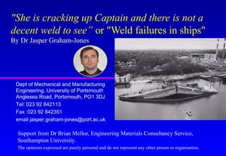
SlideShare a Scribd company logo
1 of 53
"She is cracking up Captain and there is not a
decent weld to see” or "Weld failures in ships"
By Dr Jasper Graham-Jones
Support from Dr Brian Mellor, Engineering Materials Consultancy Service,
Southampton University.
The opinions expressed are purely personal and do not represent any other person or organisation.
Dept of Mechanical and Manufacturing
Engineering, University of Portsmouth
Anglesea Road, Portsmouth, PO1 3DJ
Tel: 023 92 842113
Fax :023 92 842351
email jasper.graham-jones@port.ac.uk
Ship Failure & Loss of Life
1930’s Welded ships, Manual Metal Arc
Liberty Ship failures. WW2 +250 ships fractured or
cracked; 19 of these broke completely in two.
Fracture Mechanics comes of age!
Factors:- stress concentration, high tensile stress,
relatively low temperature, susceptible steel
•Titanic (14 April 1912) Weak rivets
and Brittle steel hull.
Esso
Manhattan
29 March
1943 at the
entrance to
New York
Harbour
John P. Gaines,
November 1943. Vessel
broke in two off Shumagin
Aleutians With the loss of
ten lives
Schenectady,
A liberty Tanker,
16 January 1943,
split in two while
moored in calm
water.
Only 24 hrs old
Post-War Ship Failures
Tyne Bridge, Kow loon Bridge, Longitudinal beam cut
and weld either side of the bulk head frame 65. Poor
welding design, laminar tearing, fractures, etc?
Derbyshire 9/10 Sept 1980, associated with poor
structural strength, and poor design of hatch covers.
(doubled skinned)
Torrey Canyon, Ran aground (19th March 1967)
Costly £ Billions: insurance and life expectancy
Many Lives, Environmental Damage: who is affected?
Welding Methods
Manual Metal Arc (Most common in ship building)
MIG (Easy to use, but not as portable)
TIG (Mix of above, but harder)
Submerged metal arc.
Gas welding
Solid phase bonding (explosive welding, Friction Stir)
Electron beam & Laser Welding
Welding Defects
Solidification cracking
Lack of fusion
Lack of penetration
Porosity (Hydrogen)
Distortion
Fatigue, Corrosion, Embrittlement, etc….
Welded Joints & Defects
Butt Joint
Lap Joint
Tee, joint
Corner Joint
Edge weld
Fillet and
Full
Penetration
Ship Failure 2
Tanker 1 Failure
Force 8 gale in the Indian Ocean, land 800 mile.
Noise & vibration at the bow
Witness:- Irish deckhand, Mast Lights
•Bow disappears???
•What would YOU do next?
•Sailed 1200 miles in reverse to destination in India.
No.1
No.2
Photo 37, Side longitudinal 27 Cracked through
(1) Fatigue crack at toe of Bracket
(2)Longitudinal detached (cracked or never connected?)
1
2
Photo 38 Bracket at side longitudinal 29, Note renewed bracket is smaller
than original. Remains of original bracket are visible
Not renewed and L26 fractured at weld
Highly corroded non-renewed longitudinal (see photo 46)
What happen?
Many experts sent to photograph and assess ship.
Design change to a fuel efficient engine thus no bow
fuel tank installed.
Fuel tank considered as a stressed member.
Corrosion Fatigue, cracks originating from the welds
on one side. Rapid crack growth, considerable
distortion, and final fracture on far side.
Tanker Failure 2
Background, Super tanker 250,000 Tonnes, 20,000 T
water ballast, Oil cargo just unloaded.
Greek owners, Japanese built, USA standards, British
Insurer (Lloyds), repaired in Singapore.
Failed in Amsterdam, Holland at Shell Oil terminal.
Loud bang and ship moved and strained on it’s ropes
from the quay side.
Ship Failures30metreFracturein
25-30mmSteelplate
Failure
Initial unexpected soft grounding
Loud bang, and ship movement caused by 20kT of
water.
Dry dock: 30m (90ft) crack through 25-30 mm thick
steel plate.
Many internal weld failures and buckled steel
members.
Repair cost £10 million, not including loss of trade
What happened?
30m brittle fracture, then escaping ballast water causes
bent steel sections and failed welds.
Material of poor quality. (low temperature brittleness,
sulfide inclusions)
Weld failures, Examine Standards, for general ships.
Fillet or Fully Penetrating welds
Fracture in bottom
plating of oil tanker
18 m fracture in 25 mm thick bottom plating.
Inside the
centre ballast
tank
Port transverse web frames.
Initial examination of ship.
Design specified fully penetration welds.
Although corrosion within standard (25% thickness).
Many welds pulled out, many crack originate from
welds.
Fillet welds not as strong, but easier and quicker to do
compared to fully penetrating.
Ship has fillet welds????
Selection of samples for laboratory
examination
Setup Metallurgical Inspection
Visit site, cut out 3/4 Tonne of samples.
Take before and after photos, detail exact locations
and record on samples. Securely pack in box for
shipping
Set up lab, dry storage, logging samples, photographs,
agree samples with all parties.
Layout in lab and agree which smaller samples to cut
from the main samples. Concentrated on fracture path.
Agree cutting method as some methods can damage
samples. (Make sure samples are not cleaned)
Laboratory
investigation
Underside of face plate on
transverse web just above
diagonal stiffener.
Transverse section at S. 16 mm gap
between transverse web and face
plate has been “filled” with weld
metal.
Laboratory
investigation
continued
Transverse section through
diagonal stiffener and upper and
lower sections of transverse web.
Results
Lack of penetration and fusion
Mix of old and new repair welds
Considerable weld build up to conceal poor fit up.
Some cracked welds not repaired (old fatigue marks)
and painted over (paint deep inside cracks).
Although outside profile good, large pores at weld
centre.
Weld details
Poor fit up “cured” by filling gap with weld metal.
Misalignment of upper and lower sections of
transverse web.
True weld leg lengths as small as 2 mm. Corrosion
reduced effective weld throat size.
Weld details continued
Weld between upper and lower sections of transverse
web should be a butt weld not a fillet weld.
This had no effect on the static strength of the joint but
the fatigue strength of a butt weld is 1.6 times that of a
well prepared fillet weld.
Welds and structural failure
Welded structures fracture
along welds so FE models
must replicate this.
Use sub-models of weld details
Load elongation on 5 mm
element corresponding to fillet
weld leg length.
Input into main FE model.
Pull off failure of fillet welded bracket.
Local Materials Properties
•Use an instrumented
microhardness technique with a
spherical indenter to derive the
stress-strain curve for local
regions of a weld.
•Modelling of complex failure
sequences in welded structures
using FE is hampered by lack of
local material properties.
Conclusions continued
The failure mode is only part of the story.
Need to answer question, “What is special about this
part?”.
Tanker 2 failure conclusions
Poor build and repair, (likely known to owner??)
Uneven loading with full ballast tanks.
Soft mud grounding. (Owners requested non-
grounding berth)
Ship unable to support own weight and that of ballast.
Longitudinal split allowing water to rush out
(10KT/min) causing further damage.
Some damage possible from dry dock.
Inspection, What happened?
One man (US) to inspect a 250,000 t Tanker, built in
Japan. Language problem?
Ship access, individual weld inspection problems?
Poor inspection in difficult conditions.
Why can’t ships be inspected like planes????
MONEY (Cost to benefit)
Overview
Ship losses are primarily caused by a number of
events, perhaps even minor when considered
individually in isolation, which conspire together in a
sequence which leads inevitably to the loss
Failures will occur, and are required to be managed
(Failure Management)
There will be the inevitable differences of opinion
depending upon particular points of view and interest.
You have to strive throughout to treat all possible
scenarios equally in terms of effort, time and depth of
analysis.
Areas of Future Research
Structural Design
– Modelling & Analysis of loading
Life Cycle Risk Management
– Corrosion rates, time variable stresses
Production Technology
– Good fit-ups & Production design detail
People Dynamics & concepts of risk assessment.
– ’Groupthink’ & ’Risky shift phenomenon'
Seacat propeller failure.
New in service, Vibration from propeller.
Dry dock, Half a blade missing (1 of 3).
Initial inspection, fatigue and brittle overload failure.
Detailed inspection, small pore, and welding heat
affected zones around fatigue initiation sites.
Cause of propeller failure
Overlay welded to repair a casting problem.
Poor finishing and NDT (Dye penetrate).
Small pore, stress concentration, leading to fatigue
initiation.
Crack growth, followed by multiple fatigue initiation
sites and rapid crack growth around welds
Possible damage or excessive wear to bearings.
Metallurgical testing methods
Eye, magnifying glass, (cracks, distortion)
Stereo low powered microscope. Cut samples, polish
smooth (stain) and examine for heat affected zones.
High power microscope, Electron beam microscope
(Fatigue striations, inclusions, etc).
Local materials properties
Use an instrumented microhardness technique with a
spherical indenter to derive the stress-strain curve for local
regions of a weld.

More Related Content

What's hot

Fabrication of metal matrix composites using stir casting method
Fabrication of metal matrix composites using stir casting methodFabrication of metal matrix composites using stir casting method
Fabrication of metal matrix composites using stir casting methodAbhishekKumarSingh252
 
Metal forming processes full
Metal forming processes fullMetal forming processes full
Metal forming processes fullNaman Dave
 
Casting Quality Control
Casting Quality ControlCasting Quality Control
Casting Quality Controlvins049
 
Ashby naturalmaterials
Ashby naturalmaterialsAshby naturalmaterials
Ashby naturalmaterialsAyuob Yahay
 
Welding technology by A.Vinoth Jebaraj
Welding technology by A.Vinoth JebarajWelding technology by A.Vinoth Jebaraj
Welding technology by A.Vinoth JebarajVinoth Jebaraj A
 
Wis5 welding consumables 18
Wis5 welding consumables 18Wis5 welding consumables 18
Wis5 welding consumables 18Thang Do Minh
 
INTERMETALLICS
INTERMETALLICSINTERMETALLICS
INTERMETALLICSN.Prakasan
 
Ductile to brittle transition
Ductile to brittle transitionDuctile to brittle transition
Ductile to brittle transitionBilal
 
Metallography material engineering
Metallography material engineeringMetallography material engineering
Metallography material engineeringsatyendraahirwar
 
Fracture mechanics
Fracture mechanicsFracture mechanics
Fracture mechanicsDeepak Samal
 
Fsw optimization for dissimilar aluminium alloys (Presentation)
Fsw optimization for dissimilar aluminium alloys (Presentation)Fsw optimization for dissimilar aluminium alloys (Presentation)
Fsw optimization for dissimilar aluminium alloys (Presentation)Dr. Bikram Jit Singh
 
Preparation of metal matrix composites by stir-casting method
Preparation of metal matrix composites by stir-casting methodPreparation of metal matrix composites by stir-casting method
Preparation of metal matrix composites by stir-casting methodIAEME Publication
 
Magneto and electro rheological fluid
Magneto and electro rheological fluid Magneto and electro rheological fluid
Magneto and electro rheological fluid explosionengineers
 
Fsw friction stir welding
Fsw friction stir weldingFsw friction stir welding
Fsw friction stir weldingVaibhav Patil
 

What's hot (20)

Fabrication of metal matrix composites using stir casting method
Fabrication of metal matrix composites using stir casting methodFabrication of metal matrix composites using stir casting method
Fabrication of metal matrix composites using stir casting method
 
Metal forming processes full
Metal forming processes fullMetal forming processes full
Metal forming processes full
 
Casting Quality Control
Casting Quality ControlCasting Quality Control
Casting Quality Control
 
Ashby naturalmaterials
Ashby naturalmaterialsAshby naturalmaterials
Ashby naturalmaterials
 
Welding technology by A.Vinoth Jebaraj
Welding technology by A.Vinoth JebarajWelding technology by A.Vinoth Jebaraj
Welding technology by A.Vinoth Jebaraj
 
Wis5 welding consumables 18
Wis5 welding consumables 18Wis5 welding consumables 18
Wis5 welding consumables 18
 
Laser_ arc hybrid welding
Laser_ arc hybrid weldingLaser_ arc hybrid welding
Laser_ arc hybrid welding
 
Welding fixtures
Welding fixturesWelding fixtures
Welding fixtures
 
Welding Inspection
Welding InspectionWelding Inspection
Welding Inspection
 
INTERMETALLICS
INTERMETALLICSINTERMETALLICS
INTERMETALLICS
 
Ductile to brittle transition
Ductile to brittle transitionDuctile to brittle transition
Ductile to brittle transition
 
Metallography material engineering
Metallography material engineeringMetallography material engineering
Metallography material engineering
 
Welding process
Welding processWelding process
Welding process
 
Fracture mechanics
Fracture mechanicsFracture mechanics
Fracture mechanics
 
Fsw optimization for dissimilar aluminium alloys (Presentation)
Fsw optimization for dissimilar aluminium alloys (Presentation)Fsw optimization for dissimilar aluminium alloys (Presentation)
Fsw optimization for dissimilar aluminium alloys (Presentation)
 
Welding of ci
Welding of ciWelding of ci
Welding of ci
 
Preparation of metal matrix composites by stir-casting method
Preparation of metal matrix composites by stir-casting methodPreparation of metal matrix composites by stir-casting method
Preparation of metal matrix composites by stir-casting method
 
Stress corrosion cracking
Stress corrosion crackingStress corrosion cracking
Stress corrosion cracking
 
Magneto and electro rheological fluid
Magneto and electro rheological fluid Magneto and electro rheological fluid
Magneto and electro rheological fluid
 
Fsw friction stir welding
Fsw friction stir weldingFsw friction stir welding
Fsw friction stir welding
 

Viewers also liked

Weld Defects and Material Properties - Paper
Weld Defects and Material Properties - PaperWeld Defects and Material Properties - Paper
Weld Defects and Material Properties - PaperBrett Leary
 
PICTURES-SASOL-RLL1-LRC-KP795-RLL1-NOV-DEC-16
PICTURES-SASOL-RLL1-LRC-KP795-RLL1-NOV-DEC-16PICTURES-SASOL-RLL1-LRC-KP795-RLL1-NOV-DEC-16
PICTURES-SASOL-RLL1-LRC-KP795-RLL1-NOV-DEC-16Edmond GOUGNARD
 
Arc Welding
Arc WeldingArc Welding
Arc Weldingsonia4v
 
Subsea Hyperbaric Welding for Pipeline Repair
Subsea Hyperbaric Welding for Pipeline RepairSubsea Hyperbaric Welding for Pipeline Repair
Subsea Hyperbaric Welding for Pipeline RepairNeil Woodward
 
Cbc shielded metal arc welding nc ii
Cbc   shielded metal arc welding nc iiCbc   shielded metal arc welding nc ii
Cbc shielded metal arc welding nc iiLennard Charles
 
Quality is a cost
Quality is a costQuality is a cost
Quality is a costbatch18
 
arc_welding_safety[1]
arc_welding_safety[1]arc_welding_safety[1]
arc_welding_safety[1]HARSHAL KHODE
 
introduction to engg materials
introduction to engg materialsintroduction to engg materials
introduction to engg materialsRavish Roy
 
Manufacturing Practice 2
Manufacturing Practice 2Manufacturing Practice 2
Manufacturing Practice 2syfadillahabu
 
1499 methods for charpy impact test
1499 methods for charpy impact test1499 methods for charpy impact test
1499 methods for charpy impact testSubhraprakash Mondal
 

Viewers also liked (20)

Welding defects
Welding defectsWelding defects
Welding defects
 
Weld Defects and Material Properties - Paper
Weld Defects and Material Properties - PaperWeld Defects and Material Properties - Paper
Weld Defects and Material Properties - Paper
 
Paper212
Paper212Paper212
Paper212
 
Defects and Discontinuities
Defects and DiscontinuitiesDefects and Discontinuities
Defects and Discontinuities
 
Fatigue Mechanics of Materials
Fatigue Mechanics of MaterialsFatigue Mechanics of Materials
Fatigue Mechanics of Materials
 
PICTURES-SASOL-RLL1-LRC-KP795-RLL1-NOV-DEC-16
PICTURES-SASOL-RLL1-LRC-KP795-RLL1-NOV-DEC-16PICTURES-SASOL-RLL1-LRC-KP795-RLL1-NOV-DEC-16
PICTURES-SASOL-RLL1-LRC-KP795-RLL1-NOV-DEC-16
 
Arc Welding
Arc WeldingArc Welding
Arc Welding
 
Welding
WeldingWelding
Welding
 
Impact of metals
Impact of metalsImpact of metals
Impact of metals
 
What is Fatigue in Mechanics Of Material .
What is Fatigue in Mechanics Of Material .What is Fatigue in Mechanics Of Material .
What is Fatigue in Mechanics Of Material .
 
Subsea Hyperbaric Welding for Pipeline Repair
Subsea Hyperbaric Welding for Pipeline RepairSubsea Hyperbaric Welding for Pipeline Repair
Subsea Hyperbaric Welding for Pipeline Repair
 
Cbc shielded metal arc welding nc ii
Cbc   shielded metal arc welding nc iiCbc   shielded metal arc welding nc ii
Cbc shielded metal arc welding nc ii
 
Quality is a cost
Quality is a costQuality is a cost
Quality is a cost
 
arc_welding_safety[1]
arc_welding_safety[1]arc_welding_safety[1]
arc_welding_safety[1]
 
Weldingintro
WeldingintroWeldingintro
Weldingintro
 
introduction to engg materials
introduction to engg materialsintroduction to engg materials
introduction to engg materials
 
Arc Welding
Arc WeldingArc Welding
Arc Welding
 
Seminar on fatigue
Seminar on fatigueSeminar on fatigue
Seminar on fatigue
 
Manufacturing Practice 2
Manufacturing Practice 2Manufacturing Practice 2
Manufacturing Practice 2
 
1499 methods for charpy impact test
1499 methods for charpy impact test1499 methods for charpy impact test
1499 methods for charpy impact test
 

Similar to Welded Ship failures

Equipment failure - a liability or an asset? - Roger Costanzi
Equipment failure - a liability or an asset? - Roger CostanziEquipment failure - a liability or an asset? - Roger Costanzi
Equipment failure - a liability or an asset? - Roger CostanziNSW Environment and Planning
 
Manufacturing Technology-I
Manufacturing Technology-I Manufacturing Technology-I
Manufacturing Technology-I nagoorvali8
 
Electroplating - Spencer Electroplating
Electroplating - Spencer ElectroplatingElectroplating - Spencer Electroplating
Electroplating - Spencer Electroplatingspencerelectroplating
 
K.Srinivasulureddy-SNIST-Metallurgy & Material Science-UNIT-2
K.Srinivasulureddy-SNIST-Metallurgy & Material Science-UNIT-2K.Srinivasulureddy-SNIST-Metallurgy & Material Science-UNIT-2
K.Srinivasulureddy-SNIST-Metallurgy & Material Science-UNIT-2Kunduru Srinivasulu Reddy
 
Billet defects
Billet defectsBillet defects
Billet defectsZiad Salem
 
How to prevent weld failure
How to prevent weld failure How to prevent weld failure
How to prevent weld failure أحمد دعبس
 
Metallography_and_Failure_Analysis.pptx
Metallography_and_Failure_Analysis.pptxMetallography_and_Failure_Analysis.pptx
Metallography_and_Failure_Analysis.pptxOswaldo Gonzales
 
Welding presentation
Welding presentationWelding presentation
Welding presentationVaradaraj Ck
 
TALAT Lecture 3208: The Finishing of Castings
TALAT Lecture 3208: The Finishing of CastingsTALAT Lecture 3208: The Finishing of Castings
TALAT Lecture 3208: The Finishing of CastingsCORE-Materials
 
Defects in rolled sheets-A paper review
Defects in rolled sheets-A paper reviewDefects in rolled sheets-A paper review
Defects in rolled sheets-A paper reviewIRJET Journal
 
TH. hill casing failures training course Presentation 2010
TH. hill  casing failures training course Presentation 2010TH. hill  casing failures training course Presentation 2010
TH. hill casing failures training course Presentation 2010Hamidreza Shobeyri
 
WELD DEFECTS.pptx
WELD DEFECTS.pptxWELD DEFECTS.pptx
WELD DEFECTS.pptxGemDL
 

Similar to Welded Ship failures (20)

Equipment failure - a liability or an asset? - Roger Costanzi
Equipment failure - a liability or an asset? - Roger CostanziEquipment failure - a liability or an asset? - Roger Costanzi
Equipment failure - a liability or an asset? - Roger Costanzi
 
Manufacturing Technology-I
Manufacturing Technology-I Manufacturing Technology-I
Manufacturing Technology-I
 
Electroplating - Spencer Electroplating
Electroplating - Spencer ElectroplatingElectroplating - Spencer Electroplating
Electroplating - Spencer Electroplating
 
K.Srinivasulureddy-SNIST-Metallurgy & Material Science-UNIT-2
K.Srinivasulureddy-SNIST-Metallurgy & Material Science-UNIT-2K.Srinivasulureddy-SNIST-Metallurgy & Material Science-UNIT-2
K.Srinivasulureddy-SNIST-Metallurgy & Material Science-UNIT-2
 
Billet defects
Billet defectsBillet defects
Billet defects
 
How to prevent weld failure
How to prevent weld failure How to prevent weld failure
How to prevent weld failure
 
Power Point Rio Tinto Western Australia
Power Point Rio Tinto Western AustraliaPower Point Rio Tinto Western Australia
Power Point Rio Tinto Western Australia
 
Metallography_and_Failure_Analysis.pptx
Metallography_and_Failure_Analysis.pptxMetallography_and_Failure_Analysis.pptx
Metallography_and_Failure_Analysis.pptx
 
Welding presentation
Welding presentationWelding presentation
Welding presentation
 
Casing defects
Casing defectsCasing defects
Casing defects
 
3208
32083208
3208
 
TALAT Lecture 3208: The Finishing of Castings
TALAT Lecture 3208: The Finishing of CastingsTALAT Lecture 3208: The Finishing of Castings
TALAT Lecture 3208: The Finishing of Castings
 
Rolling presentation
Rolling presentationRolling presentation
Rolling presentation
 
Spencer Electroplating Service
Spencer Electroplating ServiceSpencer Electroplating Service
Spencer Electroplating Service
 
Defects in rolled sheets-A paper review
Defects in rolled sheets-A paper reviewDefects in rolled sheets-A paper review
Defects in rolled sheets-A paper review
 
Defect 4 ed
Defect 4 edDefect 4 ed
Defect 4 ed
 
3497458.ppt
3497458.ppt3497458.ppt
3497458.ppt
 
TH. hill casing failures training course Presentation 2010
TH. hill  casing failures training course Presentation 2010TH. hill  casing failures training course Presentation 2010
TH. hill casing failures training course Presentation 2010
 
2015_MST15_PPT_MIC Final
2015_MST15_PPT_MIC Final2015_MST15_PPT_MIC Final
2015_MST15_PPT_MIC Final
 
WELD DEFECTS.pptx
WELD DEFECTS.pptxWELD DEFECTS.pptx
WELD DEFECTS.pptx
 

Welded Ship failures

  • 1. "She is cracking up Captain and there is not a decent weld to see” or "Weld failures in ships" By Dr Jasper Graham-Jones Support from Dr Brian Mellor, Engineering Materials Consultancy Service, Southampton University. The opinions expressed are purely personal and do not represent any other person or organisation. Dept of Mechanical and Manufacturing Engineering, University of Portsmouth Anglesea Road, Portsmouth, PO1 3DJ Tel: 023 92 842113 Fax :023 92 842351 email jasper.graham-jones@port.ac.uk
  • 2. Ship Failure & Loss of Life 1930’s Welded ships, Manual Metal Arc Liberty Ship failures. WW2 +250 ships fractured or cracked; 19 of these broke completely in two. Fracture Mechanics comes of age! Factors:- stress concentration, high tensile stress, relatively low temperature, susceptible steel •Titanic (14 April 1912) Weak rivets and Brittle steel hull.
  • 3. Esso Manhattan 29 March 1943 at the entrance to New York Harbour John P. Gaines, November 1943. Vessel broke in two off Shumagin Aleutians With the loss of ten lives
  • 4. Schenectady, A liberty Tanker, 16 January 1943, split in two while moored in calm water. Only 24 hrs old
  • 5. Post-War Ship Failures Tyne Bridge, Kow loon Bridge, Longitudinal beam cut and weld either side of the bulk head frame 65. Poor welding design, laminar tearing, fractures, etc? Derbyshire 9/10 Sept 1980, associated with poor structural strength, and poor design of hatch covers. (doubled skinned) Torrey Canyon, Ran aground (19th March 1967) Costly £ Billions: insurance and life expectancy Many Lives, Environmental Damage: who is affected?
  • 6. Welding Methods Manual Metal Arc (Most common in ship building) MIG (Easy to use, but not as portable) TIG (Mix of above, but harder) Submerged metal arc. Gas welding Solid phase bonding (explosive welding, Friction Stir) Electron beam & Laser Welding
  • 7. Welding Defects Solidification cracking Lack of fusion Lack of penetration Porosity (Hydrogen) Distortion Fatigue, Corrosion, Embrittlement, etc….
  • 8. Welded Joints & Defects Butt Joint Lap Joint Tee, joint Corner Joint Edge weld Fillet and Full Penetration
  • 10. Tanker 1 Failure Force 8 gale in the Indian Ocean, land 800 mile. Noise & vibration at the bow Witness:- Irish deckhand, Mast Lights •Bow disappears??? •What would YOU do next? •Sailed 1200 miles in reverse to destination in India.
  • 11. No.1
  • 12. No.2
  • 13.
  • 14.
  • 15.
  • 16.
  • 17. Photo 37, Side longitudinal 27 Cracked through (1) Fatigue crack at toe of Bracket (2)Longitudinal detached (cracked or never connected?) 1 2
  • 18. Photo 38 Bracket at side longitudinal 29, Note renewed bracket is smaller than original. Remains of original bracket are visible
  • 19. Not renewed and L26 fractured at weld
  • 20. Highly corroded non-renewed longitudinal (see photo 46)
  • 21. What happen? Many experts sent to photograph and assess ship. Design change to a fuel efficient engine thus no bow fuel tank installed. Fuel tank considered as a stressed member. Corrosion Fatigue, cracks originating from the welds on one side. Rapid crack growth, considerable distortion, and final fracture on far side.
  • 22. Tanker Failure 2 Background, Super tanker 250,000 Tonnes, 20,000 T water ballast, Oil cargo just unloaded. Greek owners, Japanese built, USA standards, British Insurer (Lloyds), repaired in Singapore. Failed in Amsterdam, Holland at Shell Oil terminal. Loud bang and ship moved and strained on it’s ropes from the quay side.
  • 24. Failure Initial unexpected soft grounding Loud bang, and ship movement caused by 20kT of water. Dry dock: 30m (90ft) crack through 25-30 mm thick steel plate. Many internal weld failures and buckled steel members. Repair cost £10 million, not including loss of trade
  • 25.
  • 26. What happened? 30m brittle fracture, then escaping ballast water causes bent steel sections and failed welds. Material of poor quality. (low temperature brittleness, sulfide inclusions) Weld failures, Examine Standards, for general ships. Fillet or Fully Penetrating welds
  • 27. Fracture in bottom plating of oil tanker 18 m fracture in 25 mm thick bottom plating.
  • 28.
  • 29.
  • 30. Inside the centre ballast tank Port transverse web frames.
  • 31.
  • 32. Initial examination of ship. Design specified fully penetration welds. Although corrosion within standard (25% thickness). Many welds pulled out, many crack originate from welds. Fillet welds not as strong, but easier and quicker to do compared to fully penetrating. Ship has fillet welds????
  • 33.
  • 34. Selection of samples for laboratory examination
  • 35.
  • 36. Setup Metallurgical Inspection Visit site, cut out 3/4 Tonne of samples. Take before and after photos, detail exact locations and record on samples. Securely pack in box for shipping Set up lab, dry storage, logging samples, photographs, agree samples with all parties. Layout in lab and agree which smaller samples to cut from the main samples. Concentrated on fracture path. Agree cutting method as some methods can damage samples. (Make sure samples are not cleaned)
  • 37. Laboratory investigation Underside of face plate on transverse web just above diagonal stiffener. Transverse section at S. 16 mm gap between transverse web and face plate has been “filled” with weld metal.
  • 38. Laboratory investigation continued Transverse section through diagonal stiffener and upper and lower sections of transverse web.
  • 39. Results Lack of penetration and fusion Mix of old and new repair welds Considerable weld build up to conceal poor fit up. Some cracked welds not repaired (old fatigue marks) and painted over (paint deep inside cracks). Although outside profile good, large pores at weld centre.
  • 40. Weld details Poor fit up “cured” by filling gap with weld metal. Misalignment of upper and lower sections of transverse web. True weld leg lengths as small as 2 mm. Corrosion reduced effective weld throat size.
  • 41. Weld details continued Weld between upper and lower sections of transverse web should be a butt weld not a fillet weld. This had no effect on the static strength of the joint but the fatigue strength of a butt weld is 1.6 times that of a well prepared fillet weld.
  • 42. Welds and structural failure Welded structures fracture along welds so FE models must replicate this.
  • 43. Use sub-models of weld details Load elongation on 5 mm element corresponding to fillet weld leg length. Input into main FE model. Pull off failure of fillet welded bracket.
  • 44. Local Materials Properties •Use an instrumented microhardness technique with a spherical indenter to derive the stress-strain curve for local regions of a weld. •Modelling of complex failure sequences in welded structures using FE is hampered by lack of local material properties.
  • 45. Conclusions continued The failure mode is only part of the story. Need to answer question, “What is special about this part?”.
  • 46. Tanker 2 failure conclusions Poor build and repair, (likely known to owner??) Uneven loading with full ballast tanks. Soft mud grounding. (Owners requested non- grounding berth) Ship unable to support own weight and that of ballast. Longitudinal split allowing water to rush out (10KT/min) causing further damage. Some damage possible from dry dock.
  • 47. Inspection, What happened? One man (US) to inspect a 250,000 t Tanker, built in Japan. Language problem? Ship access, individual weld inspection problems? Poor inspection in difficult conditions. Why can’t ships be inspected like planes???? MONEY (Cost to benefit)
  • 48. Overview Ship losses are primarily caused by a number of events, perhaps even minor when considered individually in isolation, which conspire together in a sequence which leads inevitably to the loss Failures will occur, and are required to be managed (Failure Management) There will be the inevitable differences of opinion depending upon particular points of view and interest. You have to strive throughout to treat all possible scenarios equally in terms of effort, time and depth of analysis.
  • 49. Areas of Future Research Structural Design – Modelling & Analysis of loading Life Cycle Risk Management – Corrosion rates, time variable stresses Production Technology – Good fit-ups & Production design detail People Dynamics & concepts of risk assessment. – ’Groupthink’ & ’Risky shift phenomenon'
  • 50. Seacat propeller failure. New in service, Vibration from propeller. Dry dock, Half a blade missing (1 of 3). Initial inspection, fatigue and brittle overload failure. Detailed inspection, small pore, and welding heat affected zones around fatigue initiation sites.
  • 51. Cause of propeller failure Overlay welded to repair a casting problem. Poor finishing and NDT (Dye penetrate). Small pore, stress concentration, leading to fatigue initiation. Crack growth, followed by multiple fatigue initiation sites and rapid crack growth around welds Possible damage or excessive wear to bearings.
  • 52. Metallurgical testing methods Eye, magnifying glass, (cracks, distortion) Stereo low powered microscope. Cut samples, polish smooth (stain) and examine for heat affected zones. High power microscope, Electron beam microscope (Fatigue striations, inclusions, etc).
  • 53. Local materials properties Use an instrumented microhardness technique with a spherical indenter to derive the stress-strain curve for local regions of a weld.