This document provides information on the various auxiliary systems used in hydro power plants, including:
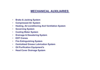
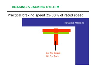
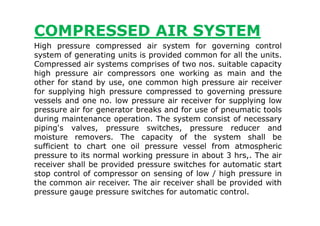
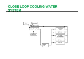
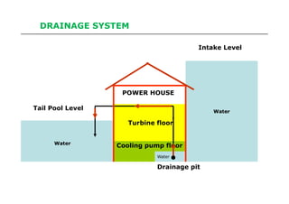
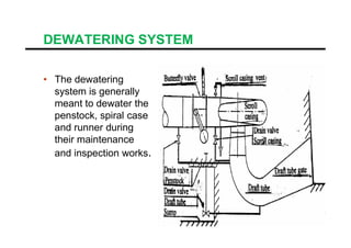
- Braking and jacking, compressed air, heating/cooling, governing, cooling water, drainage, and mechanical auxiliary systems.
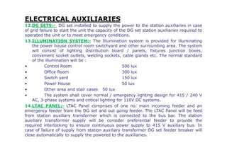
- Electrical auxiliary systems like bus ducts, transformers, cables, switchgear, protection systems, and control/monitoring panels.
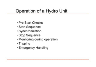
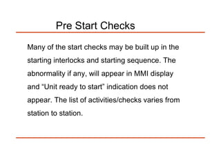
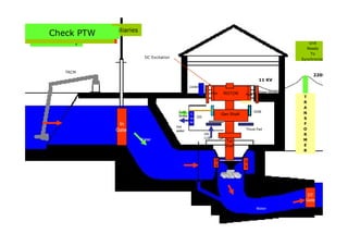
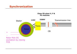
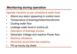
- Operation procedures including pre-start checks, normal start/stop sequences, synchronization, and emergency handling.
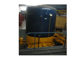
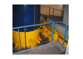
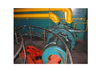
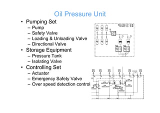
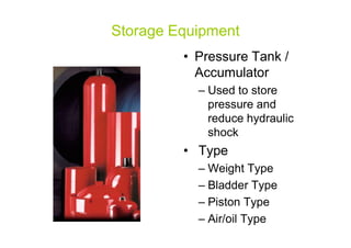
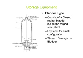
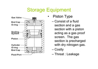
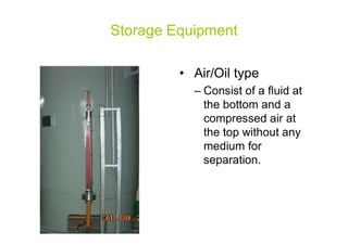
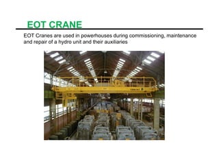
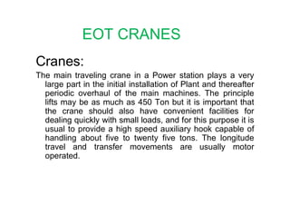
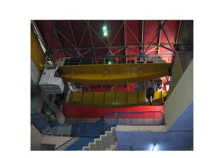
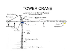
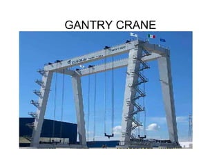
- Key components of sub-systems like pressure tanks, compressors, pumps, valves and details of lubrication, ventilation, fire protection and crane systems.