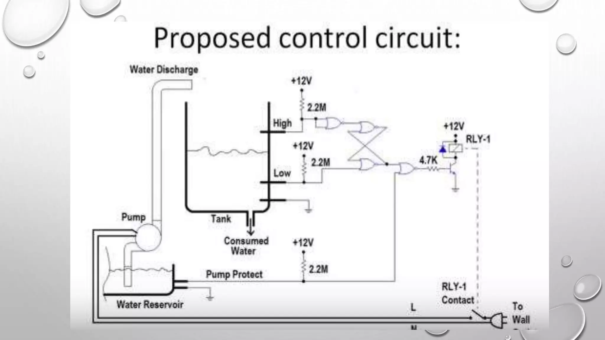
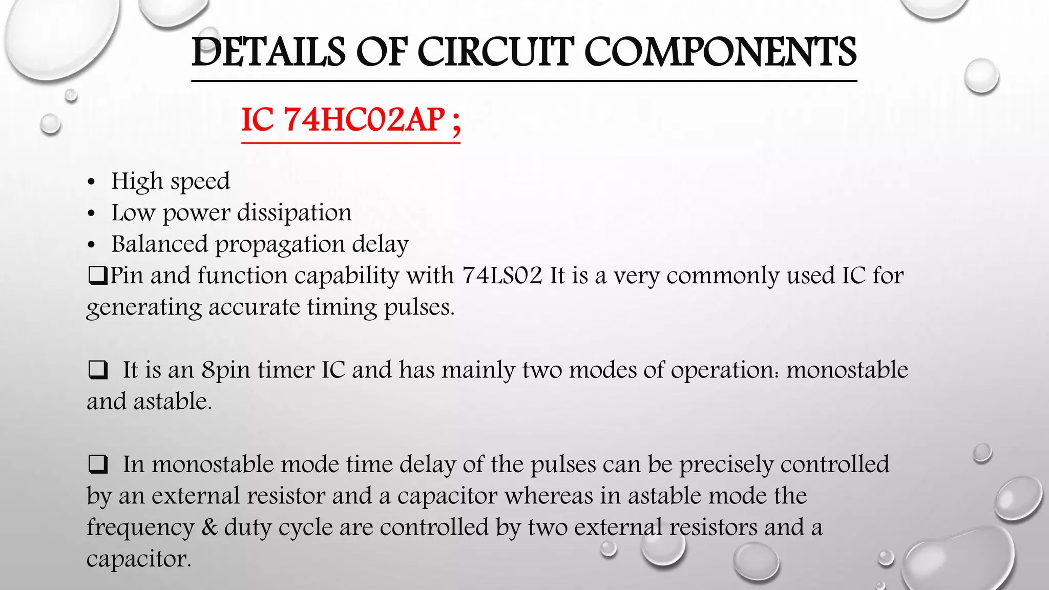
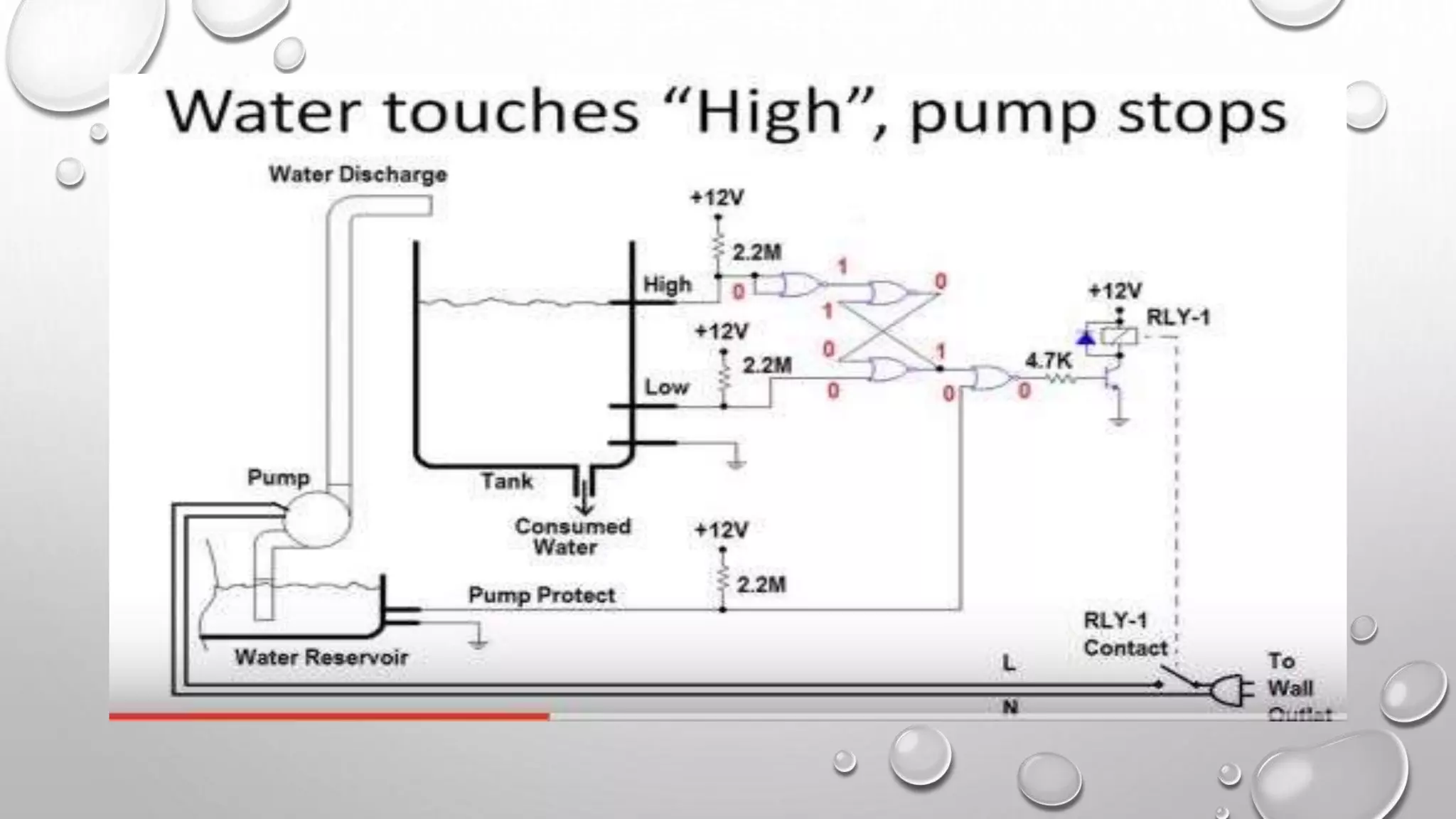
This document describes a water level control circuit designed by a group of students. It discusses both manual and automatic methods for controlling water level in a tank. The automatic method uses a float sensor to detect the water level and feeds this information to a controller, which then compares it to the desired level and controls an output valve accordingly. This provides more accurate and reliable control than the manual method, which relies on human observation. The document also provides details of the circuit components used, including resistors, IC timer chips, LEDs, and a diagram of pin connections for the IC. It discusses applications and advantages of a water level indicator circuit.