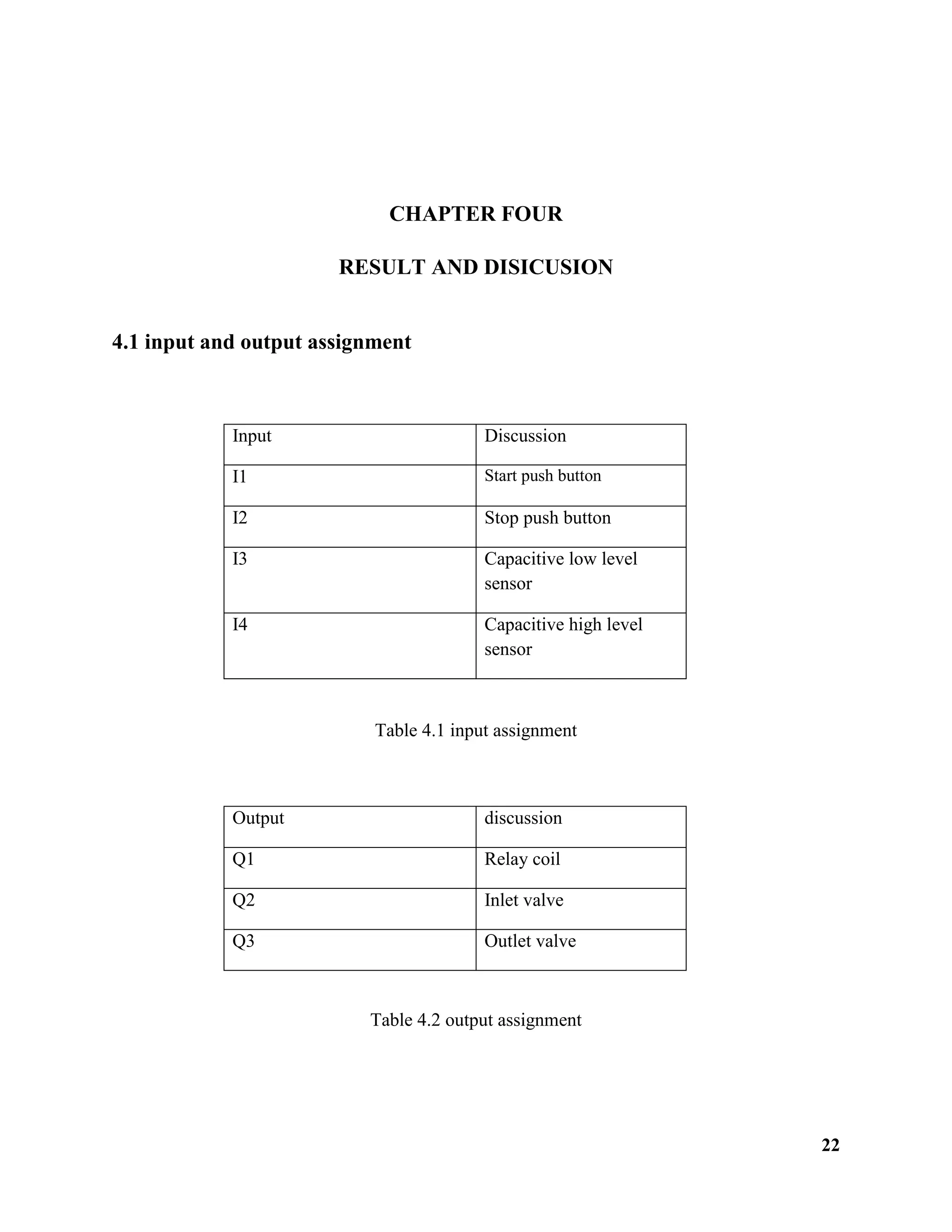
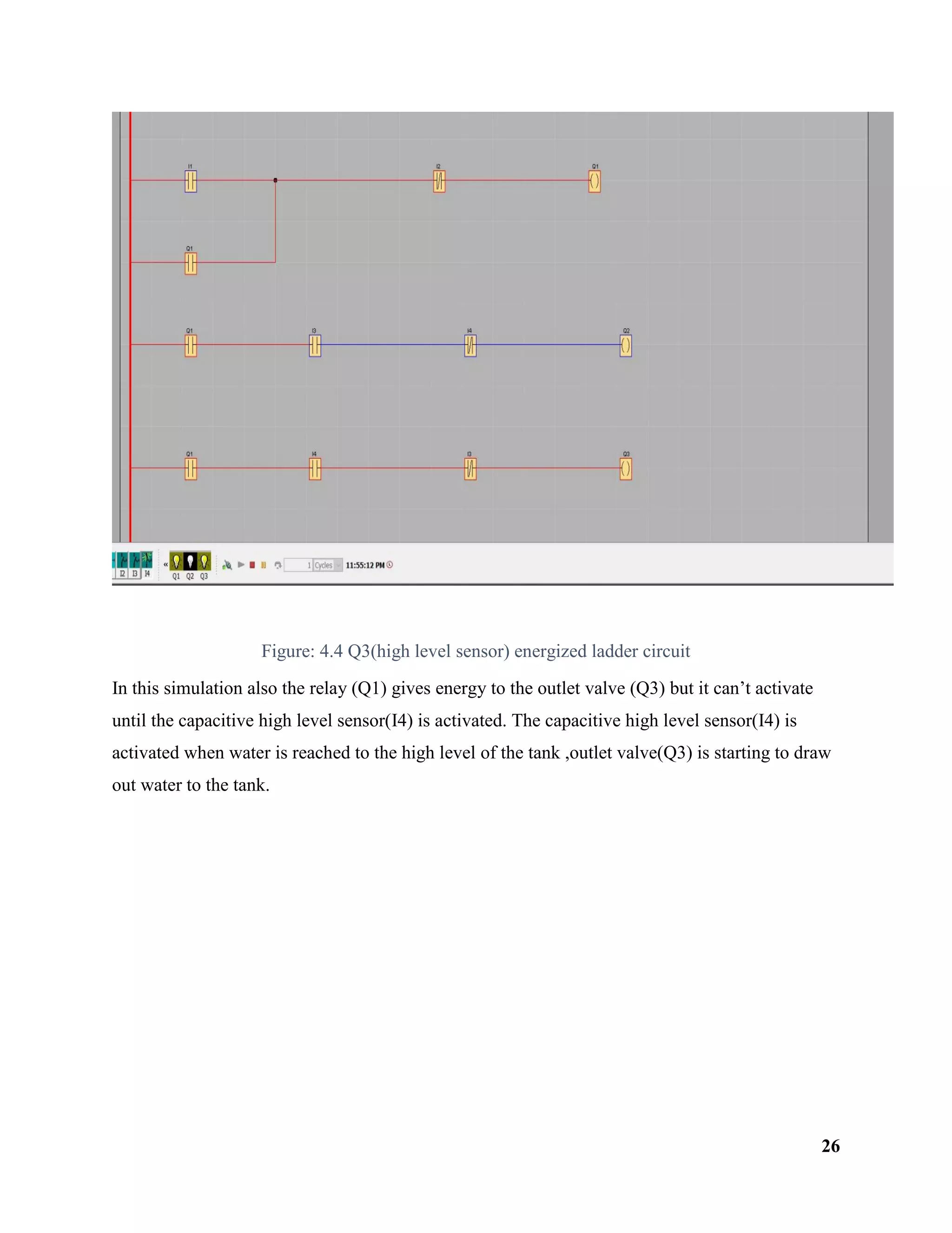
MEKELLE UNIVERSITY
Ethiopian Institute Technology Mekelle (Eit-m)
Schools of Electrical and Computer Engineering
Stream of Industrial Control and Instrumentation
Project Title:- Automatic Water Level Controller Using
Programmable Logic Control
NAMES IDNUMBERS
1. ASNAKE MOGES-----------------------------------------EIT-M/UR96814/08
2. BIRHANU HAGOS -----------------------------------------EIT-M/96902/08
3. HILUF HAFTU ------------------------------------------EIT-M/UR122025/ 09
SUBMITTED TO: INS. KINFE LEAKE(MSC.)
SUBMITIONDATE:09/11/2011E.C
Mekelle, Tigray, Ethiopia
i
ACKNOWLEDGEMENT
First of all, we would like to express our gratitude for our GOD to help us the accomplishment of
this project work. Secondly, thanks to our respected advisor KINFE L. (M.sc), for the guidance
and support that, he has provided throughout the project of this work. We would like to thank all
our friends and faculty members, Department of Electrical and Computer engineering, for their
extreme help and advise us.
ii
ABSTRACT
Automatic Water Level Controller is a project that has been proposed to maintain the water level
at the certain point. The project has two actuators and two capacitive sensors to control the water
level, which are pump and valve. The pump draws water to the tank and the valve can enable or
disable the outflow from the tank. When the water is higher from the capacitive high level
sensor, then the valve will automatically on and the water will decrease to the capacitive low
level sensor. But when the water reaches capacitive low level sensor, then the valve will off and
the pump will draw the water until reach the capacitive high level sensor. This project uses the
PLC as the controller to control the water in and water out
iii
Contents
ACKNOWLEDGEMENT .............................................................................................................................i
ABSTRACT.................................................................................................................................................. ii
List of figures............................................................................................................................................... iv
List of Acronyms ........................................................................................................................................ v
Key Words:............................................................................................................................................... v
1.1 Problem Statement..................................................................................................................................3
1.2 Objective.................................................................................................................................................3
1.2.1 General objective .............................................................................................................................3
1.2.2 Specific objective.............................................................................................................................3
1.3 Scope of the project ................................................................................................................................3
1.4 Methodology...........................................................................................................................................4
3.1 Block diagram of water level controller .................................................................................................7
3.2 Working principle of block diagram.......................................................................................................7
3.3 Block diagram Explanation.....................................................................................................................8
3.3.1 Rectifier and Filter...........................................................................................................................8
3.3.2 SMPS (switch mode power supply).................................................................................................8
3.3.3 Liquid level sensor...........................................................................................................................9
3.3.4 Programmable logic controller.........................................................................................................9
3.3.5 Relay unit.........................................................................................................................................9
3.4 Introduction to PLC ................................................................................................................................9
3.5 The Advantages and applications of PLC.............................................................................................10
3.6 The applications of PLC .......................................................................................................................10
3.7 Basic elements of PLC..........................................................................................................................11
3.7.1 CPU operating system....................................................................................................................11
3.7.2 S7-200 micro PLC .........................................................................................................................11
3.7.3 Input/output....................................................................................................................................12
3.7.4 Output module ...............................................................................................................................12
3.7.5 Input module..................................................................................................................................12
3.7.6 Memory..........................................................................................................................................12
3.7.7 Power supply..................................................................................................................................13
iv
3.8 Normally closed and normally open contactor .....................................................................................13
3.8.1 Normally closed (NC) contact .......................................................................................................13
3.8.2 Normally Open (NO) Contact........................................................................................................13
3.9 Sensor....................................................................................................................................................14
3.9.1 Level sensor ...................................................................................................................................15
3.9.2 classification of level sensor based on sensing points ...................................................................15
3.9.3 Capacitive level sensor...................................................................................................................16
3.10 solenoid valve .....................................................................................................................................17
3.10.1 Working principle of solenoid valve............................................................................................18
3.11 Flow chart for water level controller...................................................................................................19
3.12 Disadvantage of PLC..........................................................................................................................21
4.1 input and output assignment .................................................................................................................22
4.2 Simulation of the ladder diagram and Discussion.................................................................................23
CHAPTER FIVE ....................................................................................................................................27
5.1 Conclusion ............................................................................................................................................27
5.2 Recommendation ..................................................................................................................................27
REFERENCE..........................................................................................................................................28
List of figures
figure1.1 overfilling water of the tank ............................................................................................ 1
figure3.1 block diagram of water level controller .......................................................................... 7
figure3.2 block diagram.................................................................................................................. 8
figure3. 3 normal closed ............................................................................................................... 13
figure3.4 normal open................................................................................................................... 13
v
figure3.5 single point level sensor ................................................................................................ 15
figure3.6 multi-point level sensor................................................................................................. 16
figure3. 7 continuous level sensor ................................................................................................ 16
figure3.8 capacitance between the plates...................................................................................... 17
figure3.9solenoid valve................................................................................................................. 18
figure3.10flow chart...................................................................................................................... 19
figure:4.1 un-energized ladder circuit........................................................................................... 23
figure:4.2 Q1(coil) energized ladder circuit.................................................................................. 24
figure:4.3 Q2(low level sensor) energized ladder circuit.............................................................. 25
figure:4.4 Q3(high level sensor) energized ladder circuit ............................................................ 26
List of Acronyms
PLC……………………………………………Programmable logic controller
AC……………………………………………...Alternative current
DC………………………………………………. Direct current
NO………………………………………………Normal open
NC………………………………………………...Norma close
CPU………………………………………………. Central processing unit
C.L.L………………………………………………Capacitive low level sensor
C.H.L………………………………………………Capacitive high level sensor
FLC………………………………………………...fuzzy logic controller
PID………………………………………………….proportional, integral, derivative
SMPS………………………………………………switch mode power supply
Key Words: PLC, control system, Tankers, solenoid valve, PLC controller.
1
CHAPTER ONE
INTRODUCTION
Peoples have to drink water every day in order to rehydrate. In addition, drinking moderate
amount of water has several advantages, which have already been demonstrated, such as
maintain the balance of body fluids, controlling calories, maintaining good skin quality for
washing activity, industrial process, preparing food etc….
In this paper the controlling of water level tank is crucial mechanism in our day activity .in
Mekelle University overhead tanks it is common to observe that useful water is over flowing
from the tank.
Figure1.1 Overfilling water of the tank
2
Automation is utilized in many processes of today’s manufacturing sector. Many factories that
are creating components and parts for a variety of industries have some type of the process
automated. Robots are often used in more hazardous applications or in extremely repetitive
actions that can be economically problematic for human workers.
Some of the advantageous of automation system are:
 Decreased Overhead Costs
 Increased Productivity
 Consistency, Reliability, and Accuracy
 High Volume Production
 Increase in Safety
Controller system is a system of device or set of device, that manages, commands, directs or
regulates the behavior of other device or systems to achieve desired results. Industrial control
systems are used in industrial production for controlling equipment or machines.
PLC is a solid state or computerized industrial controller which performs discrete or sequential
logic in factory environment.
PLC based Automatic water level Controller aims to control the level of water automatically so
that water going waste due to over flow of tank can be saved easily. In this project, two liquid
level sensors are provided for overhead tank. These water level sensors are low level sensor and
high level sensor that senses the level of water and operate relays and serves inputs to
programmable logic controller. PLC is programed to control liquid level and maintain it at
specific level in over head tanks automatically so management of water is very important to
avoid its wasted.
Automatic water level controller is introduced to help the human being to manage the water in
their life. It has a few most important controllers as to control the main process of water flow so
that controller will control the process of water level which are pump and valve.
The pump draws water to the tank and the valve can enable or disable the outflow from the tank.
When the water reaches at high level sensor, then the valve will automatically on and the water
will decrease to the low level. But when the valve is open; the water will decrease to the low
level then the pump will keep running, until the valve is off. Then, the pump will automatically
off when it reaches the manual level. This project uses the PLC as the controller to control the
water in and water out.
3
1.1 Problem Statement
The traditional water tank had many disadvantages such as:
1) Traditional water level must draw the water manually to the tank when there is no water in
the tank.
2) The problem of manual control is sometimes people forget to turn off or turn on the valve.
3) To avoid the overfilling of the open container in industrial.
1.2 Objective
1.2.1 General objective
 To design an automatic water level Controller using PLC
1.2.2 Specific objective
 To simulate the water level controller using ladder diagram
 To control valve automatically
 To demystification advantage of PLC
 To draw the block diagram and flow chart of the water level controller
 To select sensor type
1.3 Scope of the project
The scope of this project is in software development:
The scope of the design was keep concise and simple to simulate with PLC.
In other words, it is not to introduce unnecessary and complexities program.
Generally, in this project analysis comfortable and well-built automatic water level controller in
the tank.
To develop a software using ladder logic diagram and FBD program
To simulate the control system using LOGO SIEMENS COMFORT SOFTWARE
In this project the control system should be study to control the overfilling of water rate in
the tank.
4
1.4 Methodology
There are a few methods that must be following to complete this project. The methods are as
follows below:
Figure 1.2 general methodologies
Literature
review
Statement
problems
Block
diagram and
flow chart
Result and
discussio
n
Conclusion and
recommendation
Problem
justification
Data
collection
Data
analysis
5
CHAPTER TWO
LITERATURE REVIEW
Tank Water Level Indicator and Controller Using Arduino by Amrit Kumar Panigrahi, Chandan
Kumar Singh, Diwesh Kumar, Nemisha Hota [13]. This paper gave the idea of using echo
method. It also helped us in making the system’s mechanism simpler. When the sound waves are
transmitted in the environment, they are reflected back as ECHO. Waves generated by the
ultrasonic sensors is sent to the water tank and their time of travelling and coming back is noted
and after few calculations we can estimate the level of water in the tank. The motor pump is
automatically turned ON when the water level becomes low and turned OFF when the tank is
full. But this project is some limitations on its complexity during installation, costly, and when
the medium which wave signal transmitted is varied the ultrasonic sensor is not measure
properly.
Yuriy H. [1] designed a PLC based system to control liquid level by using Radar sensor
remotely. This system measures the liquid level, volume, temperature, and pressure and controls
these measurements remotely. The system consists of the Radar sensor, temperature sensors,
discrete level sensors and a programmable logic controller. The PLC is programmed by the FBD
programming language. To transfer data between all the components, the communication method
that the authors choose is RS 485 bus with an ASCII based protocol. The authors state that
communication protocol actually reduces or eliminates interference during the process of data
transmission. In order to monitor the system, the authors also design a human machine interface
(HMI). Finally, the experimental result corroborates the exactitude and reliability of their system.
Pooja A. [2] carried a test on a PLC based single water tank control system using PID controller.
In their system, an HMI which is programmed on NI-Lab VIEW is connected to an Allen
Bradley Micro830 PLC through the Modbus RTU communication protocol. According to Pooja
A., this system is designed for training purpose in order to have a complete understanding of
PLC based process control system design. In their literature, some necessary modeling is
introduced, such as the water tank modeling, transducer modeling, and the control valve
modeling. Some parameters, such as the resistance of the control valve, and current to pressure
(I/P) converter, are estimated depending on the experimental data by using the method of least
squares. Furthermore, Pooja et al. applied PID algorithm into the PLC to achieve a better result.
6
The PID parameters are calculated by using Ziegler Nicholas (Z-N) method. Finally, the authors
conclude that the experimental result is matched with their prediction. These authors they had a
drawback in some cases. These are:
 They use more sensors then using more sensors cost will be increased
 They use more difficult PLC program language
 And according to Pooja A. he used PLC based PID controller to control the liquid
level
 And also according to Yuriy H. he used radar sensor remotely to control the liquid
level.
 According to Amrit Kumar Panigrahi, Chandan Kumar Singh, Diwesh Kumar,
Nemisha Hota echo is complexity during installation.Then we modify the above
drawback to:
 Two level sensors then we reduce the cost
 We use a simple PLC program language which is ladder diagram method
 We control the liquid level automatically not remotely
 We reduce the complexity as much as possible
7
CHAPTER THREE
PROJECT DESIGN
3.1 Block diagram of water level controller
Figure3.1 block diagram of water level controller
3.2 Working principle of block diagram
A full wave rectifier circuit produces an output voltage or current which is purely DC or has
some specified DC component. Full wave rectifier has some fundamental advantage over half
wave rectifier that is the average DC output voltage is higher than for half wave, the output of
full wave rectifier has much less ripple than that of the half wave rectifier producing a smoother
output wave form Electronic power supply that incorporates a switching regulator to convert
electrical power efficiently. Like other power supplies, an SMPS transfer’s power from a source
like the electrical power grid to a load. The liquid level sensors are the probe type sensors which
senses the level of liquid in the thank. Whenever the liquid lever sensors are touching the probes,
the relay coil is energized. PLC(Programmable logic controller) is a controller for our project it
has inputs as we as output ports. All liquid level sensors serve as inputs to PLC. As the liquid
sensors senses the liquid level, relay coil is energized reaches to PLC through input module. As
we have already loaded a program in PLC that controls the relay and the output of relay control
Liquid level
sensor
Transformer
Rectifier
Filter
AC supply
SMPS
PLC
Relay unit Output
device
8
its output according to user program and hence the output devices are like motor, solenoid
valves, pump are controlled through output ports.
3.3 Block diagram Explanation
Figure3.2 block diagram
3.3.1 Rectifier and Filter
A full wave rectifier circuit produces an output voltage or current which is purely DC or has
some specified DC component. Full wave rectifier has some fundamental advantage over half
wave rectifier that is the average DC output voltage is higher than for half wave, the output of
full wave rectifier has much less ripple than that of the half wave rectifier producing a smoother
output wave form.
3.3.2 SMPS (switch mode power supply)
Electronic power supply that incorporates a switching regulator to convert electrical power
efficiently. Like other power supplies, an SMPS transfer’s power from a source like the electrical
power grid to a load.
Transformer
Rectifier Bridge
VAC
Input
Regulator
Vdc
Output
Filter
9
3.3.3 Liquid level sensor
The liquid level sensors are the probe type sensor which senses the level of liquid in the tank.
Whenever the liquid lever sensors are touching the probes, the relay coil is energized. As the
working voltage of liquid sensor is 12V DC, 12V dc supply is provided through step down
transformer, then full wave rectifier and filter circuit. This serves as input to PLC; 24V DC
terminal is connected to the common terminals of relay. Hence, it gives +24V DC at the output
which is further connected to the input parts of the PLC.
3.3.4 Programmable logic controller
Programmable logic controller is a controller for this projects it has inputs as well as output
ports. All liquid level sensors serve as inputs to PLC. As the liquid sensors senses the liquid
level, relay coil is energized and +24VDC reaches to PLC through input module. As we have
already loaded program in PLC, it gives output according to user program and hence the output
devices are like indicators, solenoid valves, pump are controlled through output ports.
3.3.5 Relay unit
Due to high price of PLC, it is very important to protect PLC from various abnormal conditions.
Relay unit is mainly used for over current, overheating and short circuit protection so that no
damage will occur to PLC.
3.4 Introduction to PLC
A programmable logic controller, which is usually called PLC. More commonly it is known as
programmable controller (PC). It is an electronic device operates on digital signal. It is designed
and developed for industrial application, hence also known as industrial computer. A human
being programming a PLC literally draws the diagram on the screen, using relay-contact symbols
to represent instructions to read data bits in the PLC’s memory, and relay-coil symbols to
represent instructions writing data bits to the PLC’s memory. This style of programming
developed to make it easier for industrial electricians to adapt to the new technology of PLCs.
While Ladder Diagram programming definitely has limitations compared to other computer
programming languages, it is relatively easy to learn and diagnose, which is why it remains
popular as a PLC programming language today. Typical devices connecting to a PLC’s inputs
include hand switches, process switches, sensors and typical devices connecting to a PLC’s
10
outputs include electric lamps, solenoids, relay coils, motor contactors. PLC is simply
constructing a set of instructions.
There are several ways to look at a program such as:
 Ladder logic
 statement lists
 Functional block diagrams.
But the project is used as a ladder logic diagram (LAD) is one programming language used with
PLC. Ladder logic uses components that resemble elements used in a line diagram format to
describe hard-wired control. The left vertical line of a ladder logic diagram represents the power
or energized conductor. The output element or instruction represents the neutral or return path of
the circuit. The right vertical line, which represents the return path on a hard-wired control line
diagram, is omitted.
3.5 The Advantages and applications of PLC
The advantages of PLC are:
Rugged construction
Increased Reliability
Lower Cost
Faster Response
Easier interfacing
Remote control capability
Reprogrammed easily
Correcting errors easily and precisely
Small size
3.6 The applications of PLC
PLCs have been widely used for many applications
11
 Pumping systems
 Motor control
 System monitoring
 Energy research and etc.
3.7 Basic elements of PLC
All programmable controllers contain a CPU, memory, power supply, I/O modules, and
programmable devices.
Basic parts of the PLC are follows: -
 Processor
 Memory
 Input/output devices
 Programming panel or unit
 Power supply
The central processing unit or CPU is the brain of PLC. The size an available type of CPU will
determine thing like: the programming functions available size of the application logic
Available, amount of memory available and processing speed. Understanding the CPU can
be a complex subject and will tackle that in other articles. The central processing unit
accepts input data from various sensing devices, executes the stored user program and sends
appropriate output commands to control devices.
3.7.1 CPU operating system
The CPU has three parts
 Processor
 Memory system
 Power supply
3.7.2 S7-200 micro PLC
The S7-200 micro PLC is the smallest member of the sematic S7 family
of programmable controllers. The central processing unit (CPU) is internal to the plc. Inputs
12
and outputs are the system control points. Inputs monitor field and pumps the programming part
is the connection to the programming device. S7.200 models there are five s7-200 CPU types:
CPU 221, CPU 222, CPU 224, CPU 224XP, and CPU 226 and two power supply configurations
for each type.
3.7.3 Input/output
Input output interface is the communication link between field devices and the controllers.
Through these interfaces the processor can sense and measure physical quantities regarding a
machine or process, such as, proximity, position, motion, level, temperature, pressure, IR sensor,
limit switch sensor, etc. Based on status sensed, the CPU issues command to output devices such
as pneumatically valves, motors, -s, conveyor, etc.
The input and output section consists of:
 Input module
 Output module
3.7.4 Output module
Serves the link between PLC and field output device. The main function of output module is to
take the CPU’s control signal, electrically isolate it, and energized or de energized the module
switching device to turn on or turnoff the output field device. Example; relays, motor starter,
valves, indicator light, LED display, etc.
3.7.5 Input module
Input modules serves as the link between fields input device and the PLC’s CPU. The main
function of an input modules is to take the field device input signal, and convert it to a signal
level that the CPU can work with, and electrically isolate it, and send the signal by the way of the
back plane board to the input modules is an electronic circuit, which interfaces the field input
devices to PLC’s CPU.
Example push buttons, limit switch, selector switch, relay contact and analog sensor etc.
3.7.6 Memory
Is the storage device in the programmable logic controller there is various type of memory unit.
13
It is the area that holds the operating system and user memory. The operating system is actually
a system software that co-ordinates the PLC. Ladder program, timer and counter values are
stored in the user memory.
3.7.7 Power supply
A PLC's power supply provides all the voltage levels required for operation. The power supply
Provides internal DC current to operate the processor logic circuitry and input/output assemblies.
Common power levels used are 24V DC or 120V AC. The PLC operates on +5 and -5 dc.
Therefore, the power supply must be capable of rectifying the stepping-down of the ac input
voltage to a usable level of dc voltage.
3.8 Normally closed and normally open contactor
3.8.1 Normally closed (NC) contact
A contactor that is closed when the coil of the contactor is de energized and opened when the
coil is energized.
=> Off = Open = False = 0
Figure3. 3 normal closed
3.8.2 Normally Open (NO) Contact
A contact that is open under normal operating conditions and closes when an action is initiated
in its controller. For a contact that is part of a relay, the contact remains open when the relay is
de energized and closes when the relay is energized.
Figure3.4 normal open
14
=> On = Closed = True = 1
3.9 Sensor
A sensor is a device that detects events or changes in quantities and provides a corresponding
output, generally as an electrical or optical signal. A sensor's sensitivity indicates how much the
sensor's output changes when the input quantity being measured changes. A sensor is a device
that converts a physical condition into an electrical signal for use by the PLC. Sensors are
connected to the input of a PLC. A pushbutton is one example of a sensor that is connected to the
PLC input. An electrical signal is sent from the pushbutton to the PLC indicating the condition
(open/closed) of the pushbutton contacts. Sensor is referred to in terms of controlling the
operation of something. A sensor’s main function is to measure a controlled variable in an
accurate and continuous manner. In the manufacture industry we are typically measuring and
controlling temperature, pressure, and humidity. The information measured by the sensor must
be gathered and processed, so that appropriate actions can be taken on the controlled variable.
They are electronic devices that report to the plc the status of the system to be controlled and if
necessary, non-electrical signals are converted to electrical signals in order that they may be
accepted by the input module.
Sensor includes:
 Limit switches
 Cylinder switches
 Inductive sensor
 Capacitive sensor
 Ultrasonic sensor
 Float sensor
 Resistive sensor
 Radar sensor
 Position sensor
 Humidity sensor
 Pressure sensor
 Others
15
3.9.1 Level sensor
Sensors are classified based on the specific application of the sensor. Sensor used for measuring
humidity is termed as humidity sensor. The one used for measurement of pressure is called
pressure sensor. Sensor used for measurement of displacement is called position sensor.
In similar fashion, the sensor used for measurement of fluid levels is called a level sensor.
Level sensor detect the level of liquids and other fluids fluidized solids including slurries
granular materials and powders that exhibit an upper free surface the level measurement can be
either continuous or values. Continuous level sensors indicate whether the substance is above or
below the sensing point there are two types of level sensor.
 Liquid level sensor
 Solid level sensor
Examples of level sensors are:-Capacitive level sensor, float sensor, conductive probe, ultrasonic
sensor, radar level sensor and optical sensor etc.
Figure3.5 single point level sensor
3.9.2 classification of level sensor based on sensing points
1. Single Point Level Sensors
These sensors are used where fluid level is to be sensed only at single location.
2. Multi-point Level Sensor
These sensors are used where fluid level is to be sensed at number of locations single location.
16
Figure3.6 multi -point level sensor
3. Continuous Level Sensors
These sensors are used where fluid level at all locations is to be sensed
Figure3. 7 continuous level sensor
 From all described above the ones used in this project are capacitive level sensor.
3.9.3 Capacitive level sensor
The operation of these level sensors is based on a dielectric measuring method. All media which
are surround the sensors measuring electrode, built into the tip of the probe, change the state of
dielectric balance between the measuring electrode and the surrounding space. This disturbance
in the balance triggers a switching command inside the device. The balance can be adjusted with
a built in potentiometer so that materials with different bulk densities and correspondingly
different dielectric constant can be measured optimally. Metallic or metal clad vessels should be
earthed. In this case of plastic vessels filled with electrically conductive materials, the later
17
should be earthed. In this case of plastic vessels filled with non-conducting materials, an earthed
material band applied on the outside the vessel maybe used as counter electrode. The capacitive
level sensor works by the principle based on change of capacitive. There are two low plates in
capacitive sensor, one plate acts as insulated electrode and the other plate acts as a tank well the
Figure3.8 Capacitance between the plates
capacitance depends on the liquid level an empty tank has low capacitance while a filled tank has
higher capacitance. This change in capacitance can be measured by using an AC bridge. Main
advantages of this capacitance system include easy installation, broad application range, and
good accuracy suitable for variety of application and highly recognized and well- proven
technology.
3.10 solenoid valve
It is a combination of two functional units.
 A solenoid operator essentially consisting of a coil, core, core tube, shading coil and
springs.
 A valve body containing orifices in which a disc, diaphragm or piston Positioned
according to the type of technology used. The valve is opened or closed by movement of
the magnetic core which is drawn into a solenoid when the coil is energized which
controls the raw material and mixed material.
18
3.10.1 Working principle of solenoid valve
Solenoid converts electrical energy to mechanical energy and this energy is used to operate a
mechanical valve that is to open, close or to adjust in a position. The solenoid consists of a coil
of wire with an iron plunger that is allowed to move through the center of the coil. Below figure
shows the solenoid in the un-energized state.
Figure3.9solenoid valve
I. Energized
When the coil is energized, the resulting magnetic field pulls the plunger to the middle of the
coil.
II. Un-energized
Notice that the plunger is being held about halfway out of the coil by a spring. When the coil is
energized, the resulting magnetic field pulls the plunger to the middle of the coil. The magnetic
force is unidirectional a spring is required to return the plunger to its un-energized position. Most
applications use the solenoid as a on or off device that is, the coil is either completely energized
or switched off. However, variable-position control is possible by varying the input voltage.
19
3.11 Flow chart for water level controller
YES
NO
N YES
NO
Figure3.10 flow chart
Start
Tanker
Is L.l.s
A
Is
HLS
ACTI
End
Outlet
valve
energized
Inlet valve de
energized
Inlet valve
energized
Outlet valve
de energized
20
Advantage of Ladder Programming’s
 Lower power consumption
 Simple construction
 High efficiency
 Save water
 Save motor from dry running and increase its life
 Makes the system accurate
 Less maintenance
 Easily installed
 No man power
 It gives faster response
Disadvantage of Ladder Programming
 Moisture can affect the sensitivity
 Cleaning of probes is required due to oxidation problems
It cannot be used for uncovered Advantage of Ladder Programming
 Lower power consumption
 Simple construction
 High efficiency
 Save water
 Save motor from dry running and increase its life
 Makes the system accurate
 Less maintenance
 Easily installed
 No man power
 It gives faster response
 Tanks during rainy season
21
Disadvantage of Ladder Programming
 In industries for liquid level sensing and controlling
 Batch mixing system, and in hotels, apartments, hospitals, and office
 Speed control of dc motor
 The automatic frequency control of the supply
 Electromechanical processes in industry
3.12 Disadvantage of PLC
 Moisture can affect the sensitivity
 Cleaning of probes is required due to oxidation problem
 It cannot be used for uncovered tanks during rainy season
 It cannot handle complex situation
22
CHAPTER FOUR
RESULT AND DISICUSION
4.1 input and output assignment
Input Discussion
I1 Start push button
I2 Stop push button
I3 Capacitive low level
sensor
I4 Capacitive high level
sensor
Table 4.1 input assignment
Output discussion
Q1 Relay coil
Q2 Inlet valve
Q3 Outlet valve
Table 4.2 output assignment
23
4.2 Simulation of the ladder diagram and Discussion
The simulation of this project is by using ladder diagram of PLC (program logic control) and the
simulation of ladder diagram energized by the left vertical line and grounded by the right vertical
line.
Figure: 4. 1 un-energized ladder circuit
This ladder diagram shows in the first time after installation is fished in the tank, at this time on
energy is supplied to the controller.
24
Figure:4.2 Q1 (coil) energized ladder circuit
In this simulation the PLC activates to the relay (Q1) by dc trigger signal. After this relay (Q1) is
used to energize the whole ladder circuit and controls the futures of output device.
25
Figure: 4. 3 Q2 (low level sensor) energized ladder circuit
In this simulation the relay (Q1) gives energy to the inlet valve(Q2) but it can’t activate until the
capacitive low level sensor(I3) is activated. The capacitive low level sensor(I3) is activated when
water is reached to the low level of the tank, inlet valve(Q2) is starting to draw water to the tank.
26
Figure: 4.4 Q3(high level sensor) energized ladder circuit
In this simulation also the relay (Q1) gives energy to the outlet valve (Q3) but it can’t activate
until the capacitive high level sensor(I4) is activated. The capacitive high level sensor(I4) is
activated when water is reached to the high level of the tank ,outlet valve(Q3) is starting to draw
out water to the tank.
27
CHAPTER FIVE
CONCLUSION AND RECOMMENDATION
5.1 Conclusion
Automation of the various components around us has been widely increased to reduce human
intervention and save time. It is known that improper water management can have harmful
effects on both the system and the environment. The main objective of this project is not only to
reduce manual labor but also help save water in an efficient manner. Finally, a conclusion can
draw that this project can definitely be useful on a large scale basis due to its minimum
requirement of man power and also the installation process being easier making it more
compatible for everyone to use.
5.2 Recommendation
We are done this project using PLC (programmable logic controller) using ladder diagram then
we want to recommend for others to do this project by other software, for example using
microcontroller, FLC, PID etc. Because PLC cannot handle complex situation so in order to
reduce cost use the above example or other software’s.
The project can also be installed with ph. sensors which will help to regulate the acidity or
alkalinity of the water.
28
REFERENCE
[1] Yuri H. “PLC based system to control liquid level by using Radar sensor remotely”, 2015.
[2] Pooja A. “PLC based single water tank control system using PID controller”, 2015.
[3] V.R Jadhav “Programmable logic controller”, 2016.
[4] Pty Ltd. Rota-Loo “Environmental Equipment Composting Toilet Brochure”, 2006.
[5] L.A. Bryan and E. A. Bryan “Programmable controller Theory and implementation.”
[6] Joon Heo.A. “Security Mechanism for Automation Control in PLC-based Networks.”
[7] Jon S. Wilson “Google Books Sensor Technology Handbook.”
[8] M Gauger “automation applications that integrate wireless sensor networks.”
[9] M .varchola. Zigbee “Automation wireless sensor network.” 2007.
[10] Prof. Hesham Khairy “Automation Technology”.
[11]Crispin A.J. “Programmable logic controller and their engineering application”, first
Edition, books Britain, 1996.
[12] Stevenson J. “Fundamentals of programmable logic controller”, first edition, prentice hall,
1998.
[13] Amrit Kumar Panigrahi, Chandan Kumar Singh, Diwesh Kumar, Nemisha Hota “Tank
Water Level Indicator and Controller Using Arduino.” And al et.

power.pfd

  • 1.
    MEKELLE UNIVERSITY Ethiopian InstituteTechnology Mekelle (Eit-m) Schools of Electrical and Computer Engineering Stream of Industrial Control and Instrumentation Project Title:- Automatic Water Level Controller Using Programmable Logic Control NAMES IDNUMBERS 1. ASNAKE MOGES-----------------------------------------EIT-M/UR96814/08 2. BIRHANU HAGOS -----------------------------------------EIT-M/96902/08 3. HILUF HAFTU ------------------------------------------EIT-M/UR122025/ 09 SUBMITTED TO: INS. KINFE LEAKE(MSC.) SUBMITIONDATE:09/11/2011E.C Mekelle, Tigray, Ethiopia
  • 2.
    i ACKNOWLEDGEMENT First of all,we would like to express our gratitude for our GOD to help us the accomplishment of this project work. Secondly, thanks to our respected advisor KINFE L. (M.sc), for the guidance and support that, he has provided throughout the project of this work. We would like to thank all our friends and faculty members, Department of Electrical and Computer engineering, for their extreme help and advise us.
  • 3.
    ii ABSTRACT Automatic Water LevelController is a project that has been proposed to maintain the water level at the certain point. The project has two actuators and two capacitive sensors to control the water level, which are pump and valve. The pump draws water to the tank and the valve can enable or disable the outflow from the tank. When the water is higher from the capacitive high level sensor, then the valve will automatically on and the water will decrease to the capacitive low level sensor. But when the water reaches capacitive low level sensor, then the valve will off and the pump will draw the water until reach the capacitive high level sensor. This project uses the PLC as the controller to control the water in and water out
  • 4.
    iii Contents ACKNOWLEDGEMENT .............................................................................................................................i ABSTRACT.................................................................................................................................................. ii Listof figures............................................................................................................................................... iv List of Acronyms ........................................................................................................................................ v Key Words:............................................................................................................................................... v 1.1 Problem Statement..................................................................................................................................3 1.2 Objective.................................................................................................................................................3 1.2.1 General objective .............................................................................................................................3 1.2.2 Specific objective.............................................................................................................................3 1.3 Scope of the project ................................................................................................................................3 1.4 Methodology...........................................................................................................................................4 3.1 Block diagram of water level controller .................................................................................................7 3.2 Working principle of block diagram.......................................................................................................7 3.3 Block diagram Explanation.....................................................................................................................8 3.3.1 Rectifier and Filter...........................................................................................................................8 3.3.2 SMPS (switch mode power supply).................................................................................................8 3.3.3 Liquid level sensor...........................................................................................................................9 3.3.4 Programmable logic controller.........................................................................................................9 3.3.5 Relay unit.........................................................................................................................................9 3.4 Introduction to PLC ................................................................................................................................9 3.5 The Advantages and applications of PLC.............................................................................................10 3.6 The applications of PLC .......................................................................................................................10 3.7 Basic elements of PLC..........................................................................................................................11 3.7.1 CPU operating system....................................................................................................................11 3.7.2 S7-200 micro PLC .........................................................................................................................11 3.7.3 Input/output....................................................................................................................................12 3.7.4 Output module ...............................................................................................................................12 3.7.5 Input module..................................................................................................................................12 3.7.6 Memory..........................................................................................................................................12 3.7.7 Power supply..................................................................................................................................13
  • 5.
    iv 3.8 Normally closedand normally open contactor .....................................................................................13 3.8.1 Normally closed (NC) contact .......................................................................................................13 3.8.2 Normally Open (NO) Contact........................................................................................................13 3.9 Sensor....................................................................................................................................................14 3.9.1 Level sensor ...................................................................................................................................15 3.9.2 classification of level sensor based on sensing points ...................................................................15 3.9.3 Capacitive level sensor...................................................................................................................16 3.10 solenoid valve .....................................................................................................................................17 3.10.1 Working principle of solenoid valve............................................................................................18 3.11 Flow chart for water level controller...................................................................................................19 3.12 Disadvantage of PLC..........................................................................................................................21 4.1 input and output assignment .................................................................................................................22 4.2 Simulation of the ladder diagram and Discussion.................................................................................23 CHAPTER FIVE ....................................................................................................................................27 5.1 Conclusion ............................................................................................................................................27 5.2 Recommendation ..................................................................................................................................27 REFERENCE..........................................................................................................................................28 List of figures figure1.1 overfilling water of the tank ............................................................................................ 1 figure3.1 block diagram of water level controller .......................................................................... 7 figure3.2 block diagram.................................................................................................................. 8 figure3. 3 normal closed ............................................................................................................... 13 figure3.4 normal open................................................................................................................... 13
  • 6.
    v figure3.5 single pointlevel sensor ................................................................................................ 15 figure3.6 multi-point level sensor................................................................................................. 16 figure3. 7 continuous level sensor ................................................................................................ 16 figure3.8 capacitance between the plates...................................................................................... 17 figure3.9solenoid valve................................................................................................................. 18 figure3.10flow chart...................................................................................................................... 19 figure:4.1 un-energized ladder circuit........................................................................................... 23 figure:4.2 Q1(coil) energized ladder circuit.................................................................................. 24 figure:4.3 Q2(low level sensor) energized ladder circuit.............................................................. 25 figure:4.4 Q3(high level sensor) energized ladder circuit ............................................................ 26 List of Acronyms PLC……………………………………………Programmable logic controller AC……………………………………………...Alternative current DC………………………………………………. Direct current NO………………………………………………Normal open NC………………………………………………...Norma close CPU………………………………………………. Central processing unit C.L.L………………………………………………Capacitive low level sensor C.H.L………………………………………………Capacitive high level sensor FLC………………………………………………...fuzzy logic controller PID………………………………………………….proportional, integral, derivative SMPS………………………………………………switch mode power supply Key Words: PLC, control system, Tankers, solenoid valve, PLC controller.
  • 7.
    1 CHAPTER ONE INTRODUCTION Peoples haveto drink water every day in order to rehydrate. In addition, drinking moderate amount of water has several advantages, which have already been demonstrated, such as maintain the balance of body fluids, controlling calories, maintaining good skin quality for washing activity, industrial process, preparing food etc…. In this paper the controlling of water level tank is crucial mechanism in our day activity .in Mekelle University overhead tanks it is common to observe that useful water is over flowing from the tank. Figure1.1 Overfilling water of the tank
  • 8.
    2 Automation is utilizedin many processes of today’s manufacturing sector. Many factories that are creating components and parts for a variety of industries have some type of the process automated. Robots are often used in more hazardous applications or in extremely repetitive actions that can be economically problematic for human workers. Some of the advantageous of automation system are:  Decreased Overhead Costs  Increased Productivity  Consistency, Reliability, and Accuracy  High Volume Production  Increase in Safety Controller system is a system of device or set of device, that manages, commands, directs or regulates the behavior of other device or systems to achieve desired results. Industrial control systems are used in industrial production for controlling equipment or machines. PLC is a solid state or computerized industrial controller which performs discrete or sequential logic in factory environment. PLC based Automatic water level Controller aims to control the level of water automatically so that water going waste due to over flow of tank can be saved easily. In this project, two liquid level sensors are provided for overhead tank. These water level sensors are low level sensor and high level sensor that senses the level of water and operate relays and serves inputs to programmable logic controller. PLC is programed to control liquid level and maintain it at specific level in over head tanks automatically so management of water is very important to avoid its wasted. Automatic water level controller is introduced to help the human being to manage the water in their life. It has a few most important controllers as to control the main process of water flow so that controller will control the process of water level which are pump and valve. The pump draws water to the tank and the valve can enable or disable the outflow from the tank. When the water reaches at high level sensor, then the valve will automatically on and the water will decrease to the low level. But when the valve is open; the water will decrease to the low level then the pump will keep running, until the valve is off. Then, the pump will automatically off when it reaches the manual level. This project uses the PLC as the controller to control the water in and water out.
  • 9.
    3 1.1 Problem Statement Thetraditional water tank had many disadvantages such as: 1) Traditional water level must draw the water manually to the tank when there is no water in the tank. 2) The problem of manual control is sometimes people forget to turn off or turn on the valve. 3) To avoid the overfilling of the open container in industrial. 1.2 Objective 1.2.1 General objective  To design an automatic water level Controller using PLC 1.2.2 Specific objective  To simulate the water level controller using ladder diagram  To control valve automatically  To demystification advantage of PLC  To draw the block diagram and flow chart of the water level controller  To select sensor type 1.3 Scope of the project The scope of this project is in software development: The scope of the design was keep concise and simple to simulate with PLC. In other words, it is not to introduce unnecessary and complexities program. Generally, in this project analysis comfortable and well-built automatic water level controller in the tank. To develop a software using ladder logic diagram and FBD program To simulate the control system using LOGO SIEMENS COMFORT SOFTWARE In this project the control system should be study to control the overfilling of water rate in the tank.
  • 10.
    4 1.4 Methodology There area few methods that must be following to complete this project. The methods are as follows below: Figure 1.2 general methodologies Literature review Statement problems Block diagram and flow chart Result and discussio n Conclusion and recommendation Problem justification Data collection Data analysis
  • 11.
    5 CHAPTER TWO LITERATURE REVIEW TankWater Level Indicator and Controller Using Arduino by Amrit Kumar Panigrahi, Chandan Kumar Singh, Diwesh Kumar, Nemisha Hota [13]. This paper gave the idea of using echo method. It also helped us in making the system’s mechanism simpler. When the sound waves are transmitted in the environment, they are reflected back as ECHO. Waves generated by the ultrasonic sensors is sent to the water tank and their time of travelling and coming back is noted and after few calculations we can estimate the level of water in the tank. The motor pump is automatically turned ON when the water level becomes low and turned OFF when the tank is full. But this project is some limitations on its complexity during installation, costly, and when the medium which wave signal transmitted is varied the ultrasonic sensor is not measure properly. Yuriy H. [1] designed a PLC based system to control liquid level by using Radar sensor remotely. This system measures the liquid level, volume, temperature, and pressure and controls these measurements remotely. The system consists of the Radar sensor, temperature sensors, discrete level sensors and a programmable logic controller. The PLC is programmed by the FBD programming language. To transfer data between all the components, the communication method that the authors choose is RS 485 bus with an ASCII based protocol. The authors state that communication protocol actually reduces or eliminates interference during the process of data transmission. In order to monitor the system, the authors also design a human machine interface (HMI). Finally, the experimental result corroborates the exactitude and reliability of their system. Pooja A. [2] carried a test on a PLC based single water tank control system using PID controller. In their system, an HMI which is programmed on NI-Lab VIEW is connected to an Allen Bradley Micro830 PLC through the Modbus RTU communication protocol. According to Pooja A., this system is designed for training purpose in order to have a complete understanding of PLC based process control system design. In their literature, some necessary modeling is introduced, such as the water tank modeling, transducer modeling, and the control valve modeling. Some parameters, such as the resistance of the control valve, and current to pressure (I/P) converter, are estimated depending on the experimental data by using the method of least squares. Furthermore, Pooja et al. applied PID algorithm into the PLC to achieve a better result.
  • 12.
    6 The PID parametersare calculated by using Ziegler Nicholas (Z-N) method. Finally, the authors conclude that the experimental result is matched with their prediction. These authors they had a drawback in some cases. These are:  They use more sensors then using more sensors cost will be increased  They use more difficult PLC program language  And according to Pooja A. he used PLC based PID controller to control the liquid level  And also according to Yuriy H. he used radar sensor remotely to control the liquid level.  According to Amrit Kumar Panigrahi, Chandan Kumar Singh, Diwesh Kumar, Nemisha Hota echo is complexity during installation.Then we modify the above drawback to:  Two level sensors then we reduce the cost  We use a simple PLC program language which is ladder diagram method  We control the liquid level automatically not remotely  We reduce the complexity as much as possible
  • 13.
    7 CHAPTER THREE PROJECT DESIGN 3.1Block diagram of water level controller Figure3.1 block diagram of water level controller 3.2 Working principle of block diagram A full wave rectifier circuit produces an output voltage or current which is purely DC or has some specified DC component. Full wave rectifier has some fundamental advantage over half wave rectifier that is the average DC output voltage is higher than for half wave, the output of full wave rectifier has much less ripple than that of the half wave rectifier producing a smoother output wave form Electronic power supply that incorporates a switching regulator to convert electrical power efficiently. Like other power supplies, an SMPS transfer’s power from a source like the electrical power grid to a load. The liquid level sensors are the probe type sensors which senses the level of liquid in the thank. Whenever the liquid lever sensors are touching the probes, the relay coil is energized. PLC(Programmable logic controller) is a controller for our project it has inputs as we as output ports. All liquid level sensors serve as inputs to PLC. As the liquid sensors senses the liquid level, relay coil is energized reaches to PLC through input module. As we have already loaded a program in PLC that controls the relay and the output of relay control Liquid level sensor Transformer Rectifier Filter AC supply SMPS PLC Relay unit Output device
  • 14.
    8 its output accordingto user program and hence the output devices are like motor, solenoid valves, pump are controlled through output ports. 3.3 Block diagram Explanation Figure3.2 block diagram 3.3.1 Rectifier and Filter A full wave rectifier circuit produces an output voltage or current which is purely DC or has some specified DC component. Full wave rectifier has some fundamental advantage over half wave rectifier that is the average DC output voltage is higher than for half wave, the output of full wave rectifier has much less ripple than that of the half wave rectifier producing a smoother output wave form. 3.3.2 SMPS (switch mode power supply) Electronic power supply that incorporates a switching regulator to convert electrical power efficiently. Like other power supplies, an SMPS transfer’s power from a source like the electrical power grid to a load. Transformer Rectifier Bridge VAC Input Regulator Vdc Output Filter
  • 15.
    9 3.3.3 Liquid levelsensor The liquid level sensors are the probe type sensor which senses the level of liquid in the tank. Whenever the liquid lever sensors are touching the probes, the relay coil is energized. As the working voltage of liquid sensor is 12V DC, 12V dc supply is provided through step down transformer, then full wave rectifier and filter circuit. This serves as input to PLC; 24V DC terminal is connected to the common terminals of relay. Hence, it gives +24V DC at the output which is further connected to the input parts of the PLC. 3.3.4 Programmable logic controller Programmable logic controller is a controller for this projects it has inputs as well as output ports. All liquid level sensors serve as inputs to PLC. As the liquid sensors senses the liquid level, relay coil is energized and +24VDC reaches to PLC through input module. As we have already loaded program in PLC, it gives output according to user program and hence the output devices are like indicators, solenoid valves, pump are controlled through output ports. 3.3.5 Relay unit Due to high price of PLC, it is very important to protect PLC from various abnormal conditions. Relay unit is mainly used for over current, overheating and short circuit protection so that no damage will occur to PLC. 3.4 Introduction to PLC A programmable logic controller, which is usually called PLC. More commonly it is known as programmable controller (PC). It is an electronic device operates on digital signal. It is designed and developed for industrial application, hence also known as industrial computer. A human being programming a PLC literally draws the diagram on the screen, using relay-contact symbols to represent instructions to read data bits in the PLC’s memory, and relay-coil symbols to represent instructions writing data bits to the PLC’s memory. This style of programming developed to make it easier for industrial electricians to adapt to the new technology of PLCs. While Ladder Diagram programming definitely has limitations compared to other computer programming languages, it is relatively easy to learn and diagnose, which is why it remains popular as a PLC programming language today. Typical devices connecting to a PLC’s inputs include hand switches, process switches, sensors and typical devices connecting to a PLC’s
  • 16.
    10 outputs include electriclamps, solenoids, relay coils, motor contactors. PLC is simply constructing a set of instructions. There are several ways to look at a program such as:  Ladder logic  statement lists  Functional block diagrams. But the project is used as a ladder logic diagram (LAD) is one programming language used with PLC. Ladder logic uses components that resemble elements used in a line diagram format to describe hard-wired control. The left vertical line of a ladder logic diagram represents the power or energized conductor. The output element or instruction represents the neutral or return path of the circuit. The right vertical line, which represents the return path on a hard-wired control line diagram, is omitted. 3.5 The Advantages and applications of PLC The advantages of PLC are: Rugged construction Increased Reliability Lower Cost Faster Response Easier interfacing Remote control capability Reprogrammed easily Correcting errors easily and precisely Small size 3.6 The applications of PLC PLCs have been widely used for many applications
  • 17.
    11  Pumping systems Motor control  System monitoring  Energy research and etc. 3.7 Basic elements of PLC All programmable controllers contain a CPU, memory, power supply, I/O modules, and programmable devices. Basic parts of the PLC are follows: -  Processor  Memory  Input/output devices  Programming panel or unit  Power supply The central processing unit or CPU is the brain of PLC. The size an available type of CPU will determine thing like: the programming functions available size of the application logic Available, amount of memory available and processing speed. Understanding the CPU can be a complex subject and will tackle that in other articles. The central processing unit accepts input data from various sensing devices, executes the stored user program and sends appropriate output commands to control devices. 3.7.1 CPU operating system The CPU has three parts  Processor  Memory system  Power supply 3.7.2 S7-200 micro PLC The S7-200 micro PLC is the smallest member of the sematic S7 family of programmable controllers. The central processing unit (CPU) is internal to the plc. Inputs
  • 18.
    12 and outputs arethe system control points. Inputs monitor field and pumps the programming part is the connection to the programming device. S7.200 models there are five s7-200 CPU types: CPU 221, CPU 222, CPU 224, CPU 224XP, and CPU 226 and two power supply configurations for each type. 3.7.3 Input/output Input output interface is the communication link between field devices and the controllers. Through these interfaces the processor can sense and measure physical quantities regarding a machine or process, such as, proximity, position, motion, level, temperature, pressure, IR sensor, limit switch sensor, etc. Based on status sensed, the CPU issues command to output devices such as pneumatically valves, motors, -s, conveyor, etc. The input and output section consists of:  Input module  Output module 3.7.4 Output module Serves the link between PLC and field output device. The main function of output module is to take the CPU’s control signal, electrically isolate it, and energized or de energized the module switching device to turn on or turnoff the output field device. Example; relays, motor starter, valves, indicator light, LED display, etc. 3.7.5 Input module Input modules serves as the link between fields input device and the PLC’s CPU. The main function of an input modules is to take the field device input signal, and convert it to a signal level that the CPU can work with, and electrically isolate it, and send the signal by the way of the back plane board to the input modules is an electronic circuit, which interfaces the field input devices to PLC’s CPU. Example push buttons, limit switch, selector switch, relay contact and analog sensor etc. 3.7.6 Memory Is the storage device in the programmable logic controller there is various type of memory unit.
  • 19.
    13 It is thearea that holds the operating system and user memory. The operating system is actually a system software that co-ordinates the PLC. Ladder program, timer and counter values are stored in the user memory. 3.7.7 Power supply A PLC's power supply provides all the voltage levels required for operation. The power supply Provides internal DC current to operate the processor logic circuitry and input/output assemblies. Common power levels used are 24V DC or 120V AC. The PLC operates on +5 and -5 dc. Therefore, the power supply must be capable of rectifying the stepping-down of the ac input voltage to a usable level of dc voltage. 3.8 Normally closed and normally open contactor 3.8.1 Normally closed (NC) contact A contactor that is closed when the coil of the contactor is de energized and opened when the coil is energized. => Off = Open = False = 0 Figure3. 3 normal closed 3.8.2 Normally Open (NO) Contact A contact that is open under normal operating conditions and closes when an action is initiated in its controller. For a contact that is part of a relay, the contact remains open when the relay is de energized and closes when the relay is energized. Figure3.4 normal open
  • 20.
    14 => On =Closed = True = 1 3.9 Sensor A sensor is a device that detects events or changes in quantities and provides a corresponding output, generally as an electrical or optical signal. A sensor's sensitivity indicates how much the sensor's output changes when the input quantity being measured changes. A sensor is a device that converts a physical condition into an electrical signal for use by the PLC. Sensors are connected to the input of a PLC. A pushbutton is one example of a sensor that is connected to the PLC input. An electrical signal is sent from the pushbutton to the PLC indicating the condition (open/closed) of the pushbutton contacts. Sensor is referred to in terms of controlling the operation of something. A sensor’s main function is to measure a controlled variable in an accurate and continuous manner. In the manufacture industry we are typically measuring and controlling temperature, pressure, and humidity. The information measured by the sensor must be gathered and processed, so that appropriate actions can be taken on the controlled variable. They are electronic devices that report to the plc the status of the system to be controlled and if necessary, non-electrical signals are converted to electrical signals in order that they may be accepted by the input module. Sensor includes:  Limit switches  Cylinder switches  Inductive sensor  Capacitive sensor  Ultrasonic sensor  Float sensor  Resistive sensor  Radar sensor  Position sensor  Humidity sensor  Pressure sensor  Others
  • 21.
    15 3.9.1 Level sensor Sensorsare classified based on the specific application of the sensor. Sensor used for measuring humidity is termed as humidity sensor. The one used for measurement of pressure is called pressure sensor. Sensor used for measurement of displacement is called position sensor. In similar fashion, the sensor used for measurement of fluid levels is called a level sensor. Level sensor detect the level of liquids and other fluids fluidized solids including slurries granular materials and powders that exhibit an upper free surface the level measurement can be either continuous or values. Continuous level sensors indicate whether the substance is above or below the sensing point there are two types of level sensor.  Liquid level sensor  Solid level sensor Examples of level sensors are:-Capacitive level sensor, float sensor, conductive probe, ultrasonic sensor, radar level sensor and optical sensor etc. Figure3.5 single point level sensor 3.9.2 classification of level sensor based on sensing points 1. Single Point Level Sensors These sensors are used where fluid level is to be sensed only at single location. 2. Multi-point Level Sensor These sensors are used where fluid level is to be sensed at number of locations single location.
  • 22.
    16 Figure3.6 multi -pointlevel sensor 3. Continuous Level Sensors These sensors are used where fluid level at all locations is to be sensed Figure3. 7 continuous level sensor  From all described above the ones used in this project are capacitive level sensor. 3.9.3 Capacitive level sensor The operation of these level sensors is based on a dielectric measuring method. All media which are surround the sensors measuring electrode, built into the tip of the probe, change the state of dielectric balance between the measuring electrode and the surrounding space. This disturbance in the balance triggers a switching command inside the device. The balance can be adjusted with a built in potentiometer so that materials with different bulk densities and correspondingly different dielectric constant can be measured optimally. Metallic or metal clad vessels should be earthed. In this case of plastic vessels filled with electrically conductive materials, the later
  • 23.
    17 should be earthed.In this case of plastic vessels filled with non-conducting materials, an earthed material band applied on the outside the vessel maybe used as counter electrode. The capacitive level sensor works by the principle based on change of capacitive. There are two low plates in capacitive sensor, one plate acts as insulated electrode and the other plate acts as a tank well the Figure3.8 Capacitance between the plates capacitance depends on the liquid level an empty tank has low capacitance while a filled tank has higher capacitance. This change in capacitance can be measured by using an AC bridge. Main advantages of this capacitance system include easy installation, broad application range, and good accuracy suitable for variety of application and highly recognized and well- proven technology. 3.10 solenoid valve It is a combination of two functional units.  A solenoid operator essentially consisting of a coil, core, core tube, shading coil and springs.  A valve body containing orifices in which a disc, diaphragm or piston Positioned according to the type of technology used. The valve is opened or closed by movement of the magnetic core which is drawn into a solenoid when the coil is energized which controls the raw material and mixed material.
  • 24.
    18 3.10.1 Working principleof solenoid valve Solenoid converts electrical energy to mechanical energy and this energy is used to operate a mechanical valve that is to open, close or to adjust in a position. The solenoid consists of a coil of wire with an iron plunger that is allowed to move through the center of the coil. Below figure shows the solenoid in the un-energized state. Figure3.9solenoid valve I. Energized When the coil is energized, the resulting magnetic field pulls the plunger to the middle of the coil. II. Un-energized Notice that the plunger is being held about halfway out of the coil by a spring. When the coil is energized, the resulting magnetic field pulls the plunger to the middle of the coil. The magnetic force is unidirectional a spring is required to return the plunger to its un-energized position. Most applications use the solenoid as a on or off device that is, the coil is either completely energized or switched off. However, variable-position control is possible by varying the input voltage.
  • 25.
    19 3.11 Flow chartfor water level controller YES NO N YES NO Figure3.10 flow chart Start Tanker Is L.l.s A Is HLS ACTI End Outlet valve energized Inlet valve de energized Inlet valve energized Outlet valve de energized
  • 26.
    20 Advantage of LadderProgramming’s  Lower power consumption  Simple construction  High efficiency  Save water  Save motor from dry running and increase its life  Makes the system accurate  Less maintenance  Easily installed  No man power  It gives faster response Disadvantage of Ladder Programming  Moisture can affect the sensitivity  Cleaning of probes is required due to oxidation problems It cannot be used for uncovered Advantage of Ladder Programming  Lower power consumption  Simple construction  High efficiency  Save water  Save motor from dry running and increase its life  Makes the system accurate  Less maintenance  Easily installed  No man power  It gives faster response  Tanks during rainy season
  • 27.
    21 Disadvantage of LadderProgramming  In industries for liquid level sensing and controlling  Batch mixing system, and in hotels, apartments, hospitals, and office  Speed control of dc motor  The automatic frequency control of the supply  Electromechanical processes in industry 3.12 Disadvantage of PLC  Moisture can affect the sensitivity  Cleaning of probes is required due to oxidation problem  It cannot be used for uncovered tanks during rainy season  It cannot handle complex situation
  • 28.
    22 CHAPTER FOUR RESULT ANDDISICUSION 4.1 input and output assignment Input Discussion I1 Start push button I2 Stop push button I3 Capacitive low level sensor I4 Capacitive high level sensor Table 4.1 input assignment Output discussion Q1 Relay coil Q2 Inlet valve Q3 Outlet valve Table 4.2 output assignment
  • 29.
    23 4.2 Simulation ofthe ladder diagram and Discussion The simulation of this project is by using ladder diagram of PLC (program logic control) and the simulation of ladder diagram energized by the left vertical line and grounded by the right vertical line. Figure: 4. 1 un-energized ladder circuit This ladder diagram shows in the first time after installation is fished in the tank, at this time on energy is supplied to the controller.
  • 30.
    24 Figure:4.2 Q1 (coil)energized ladder circuit In this simulation the PLC activates to the relay (Q1) by dc trigger signal. After this relay (Q1) is used to energize the whole ladder circuit and controls the futures of output device.
  • 31.
    25 Figure: 4. 3Q2 (low level sensor) energized ladder circuit In this simulation the relay (Q1) gives energy to the inlet valve(Q2) but it can’t activate until the capacitive low level sensor(I3) is activated. The capacitive low level sensor(I3) is activated when water is reached to the low level of the tank, inlet valve(Q2) is starting to draw water to the tank.
  • 32.
    26 Figure: 4.4 Q3(highlevel sensor) energized ladder circuit In this simulation also the relay (Q1) gives energy to the outlet valve (Q3) but it can’t activate until the capacitive high level sensor(I4) is activated. The capacitive high level sensor(I4) is activated when water is reached to the high level of the tank ,outlet valve(Q3) is starting to draw out water to the tank.
  • 33.
    27 CHAPTER FIVE CONCLUSION ANDRECOMMENDATION 5.1 Conclusion Automation of the various components around us has been widely increased to reduce human intervention and save time. It is known that improper water management can have harmful effects on both the system and the environment. The main objective of this project is not only to reduce manual labor but also help save water in an efficient manner. Finally, a conclusion can draw that this project can definitely be useful on a large scale basis due to its minimum requirement of man power and also the installation process being easier making it more compatible for everyone to use. 5.2 Recommendation We are done this project using PLC (programmable logic controller) using ladder diagram then we want to recommend for others to do this project by other software, for example using microcontroller, FLC, PID etc. Because PLC cannot handle complex situation so in order to reduce cost use the above example or other software’s. The project can also be installed with ph. sensors which will help to regulate the acidity or alkalinity of the water.
  • 34.
    28 REFERENCE [1] Yuri H.“PLC based system to control liquid level by using Radar sensor remotely”, 2015. [2] Pooja A. “PLC based single water tank control system using PID controller”, 2015. [3] V.R Jadhav “Programmable logic controller”, 2016. [4] Pty Ltd. Rota-Loo “Environmental Equipment Composting Toilet Brochure”, 2006. [5] L.A. Bryan and E. A. Bryan “Programmable controller Theory and implementation.” [6] Joon Heo.A. “Security Mechanism for Automation Control in PLC-based Networks.” [7] Jon S. Wilson “Google Books Sensor Technology Handbook.” [8] M Gauger “automation applications that integrate wireless sensor networks.” [9] M .varchola. Zigbee “Automation wireless sensor network.” 2007. [10] Prof. Hesham Khairy “Automation Technology”. [11]Crispin A.J. “Programmable logic controller and their engineering application”, first Edition, books Britain, 1996. [12] Stevenson J. “Fundamentals of programmable logic controller”, first edition, prentice hall, 1998. [13] Amrit Kumar Panigrahi, Chandan Kumar Singh, Diwesh Kumar, Nemisha Hota “Tank Water Level Indicator and Controller Using Arduino.” And al et.