Download to read offline


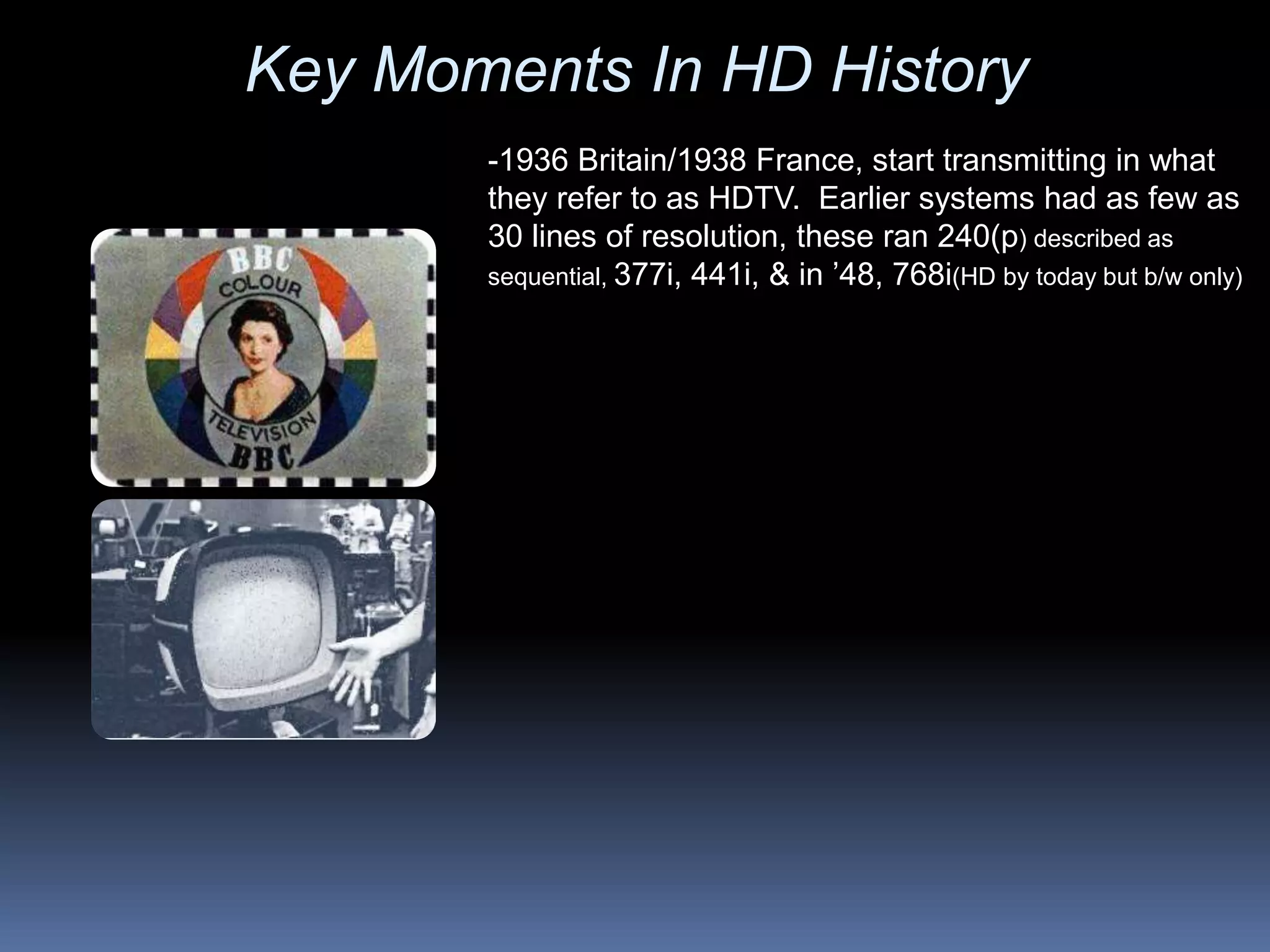

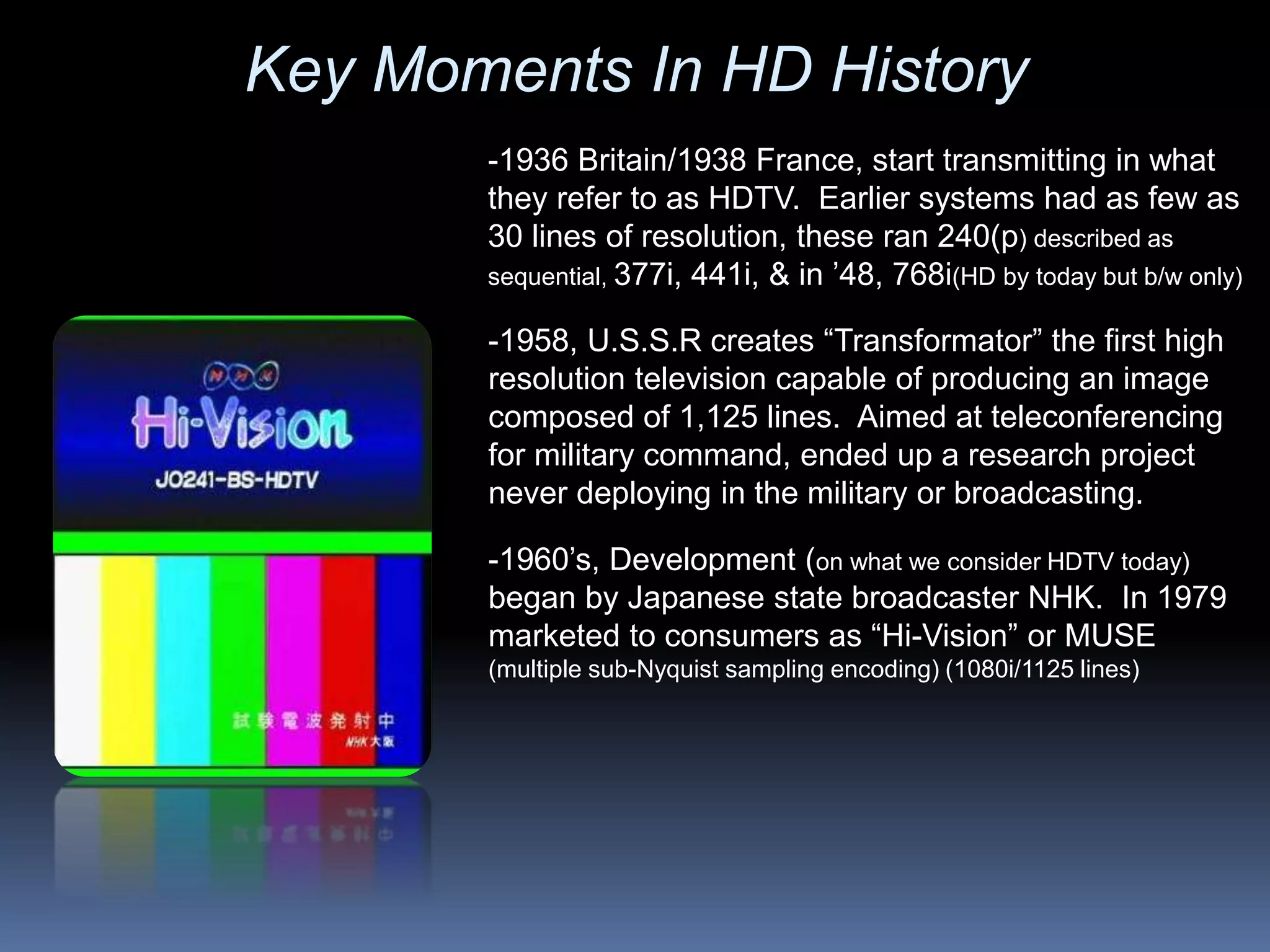


- Early experiments with high definition television transmission began in the 1930s in Britain and France, using 240 lines of resolution. - The USSR developed the first television capable of 1,125 lines of resolution in 1958 aimed at military teleconferencing. - In the 1960s, development of what we now consider HDTV began in Japan and was marketed to consumers in 1979. - Key moments in the 1980s included HDTV demonstrations in the US and the first HDTV broadcasts of the Olympic Games.