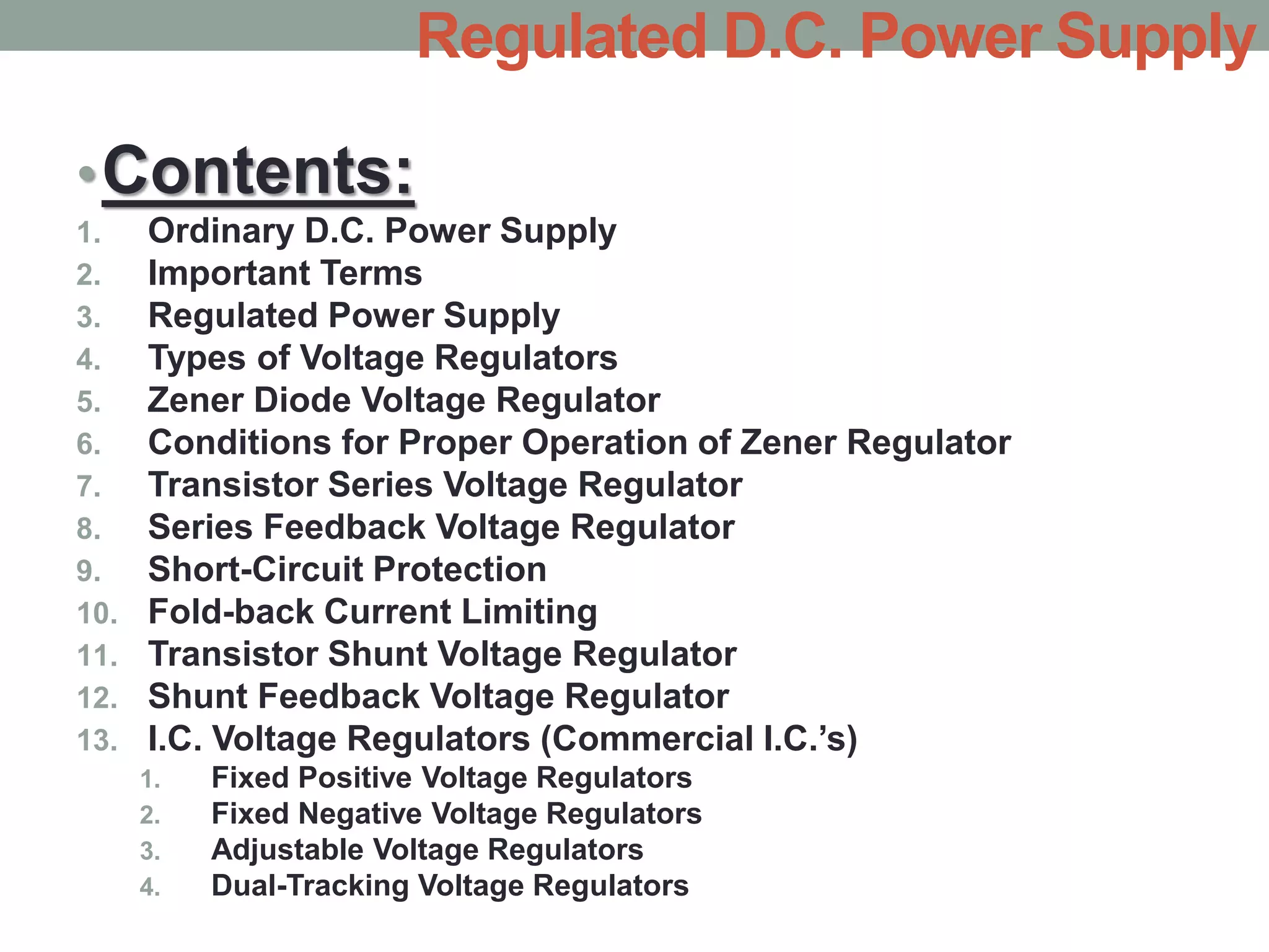
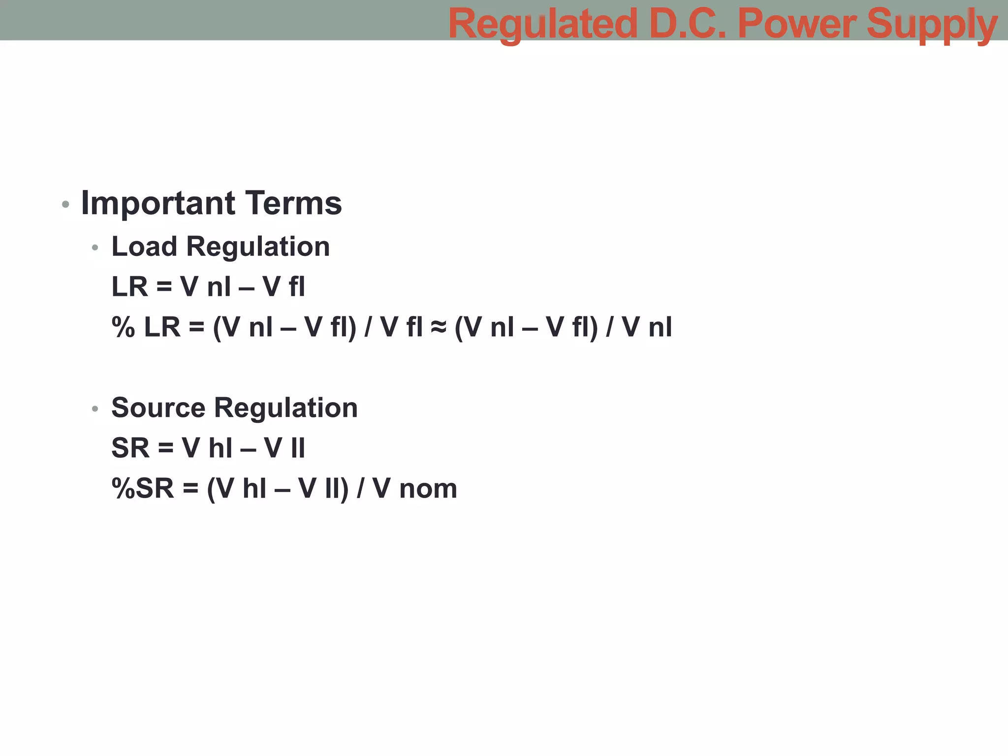
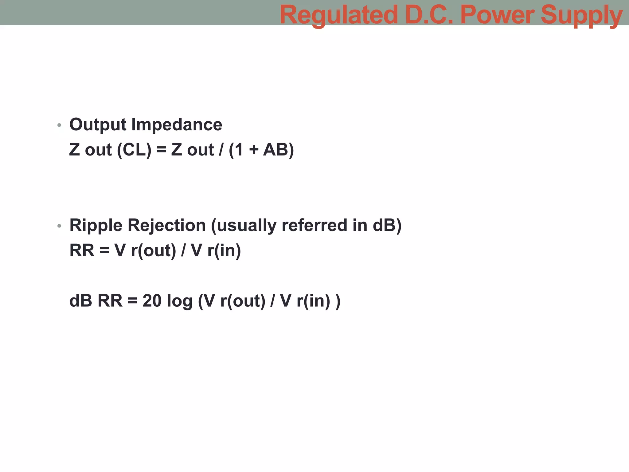
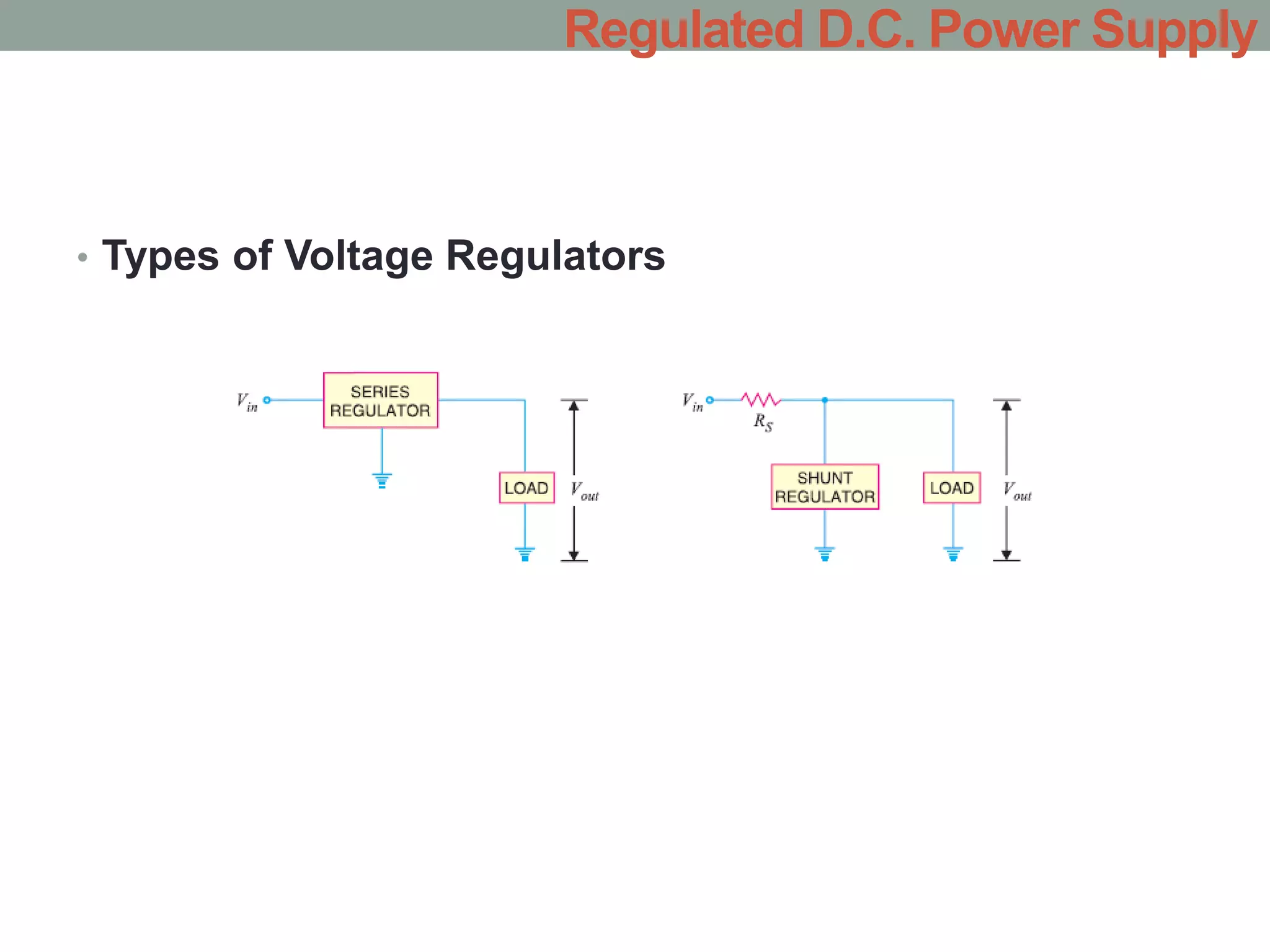
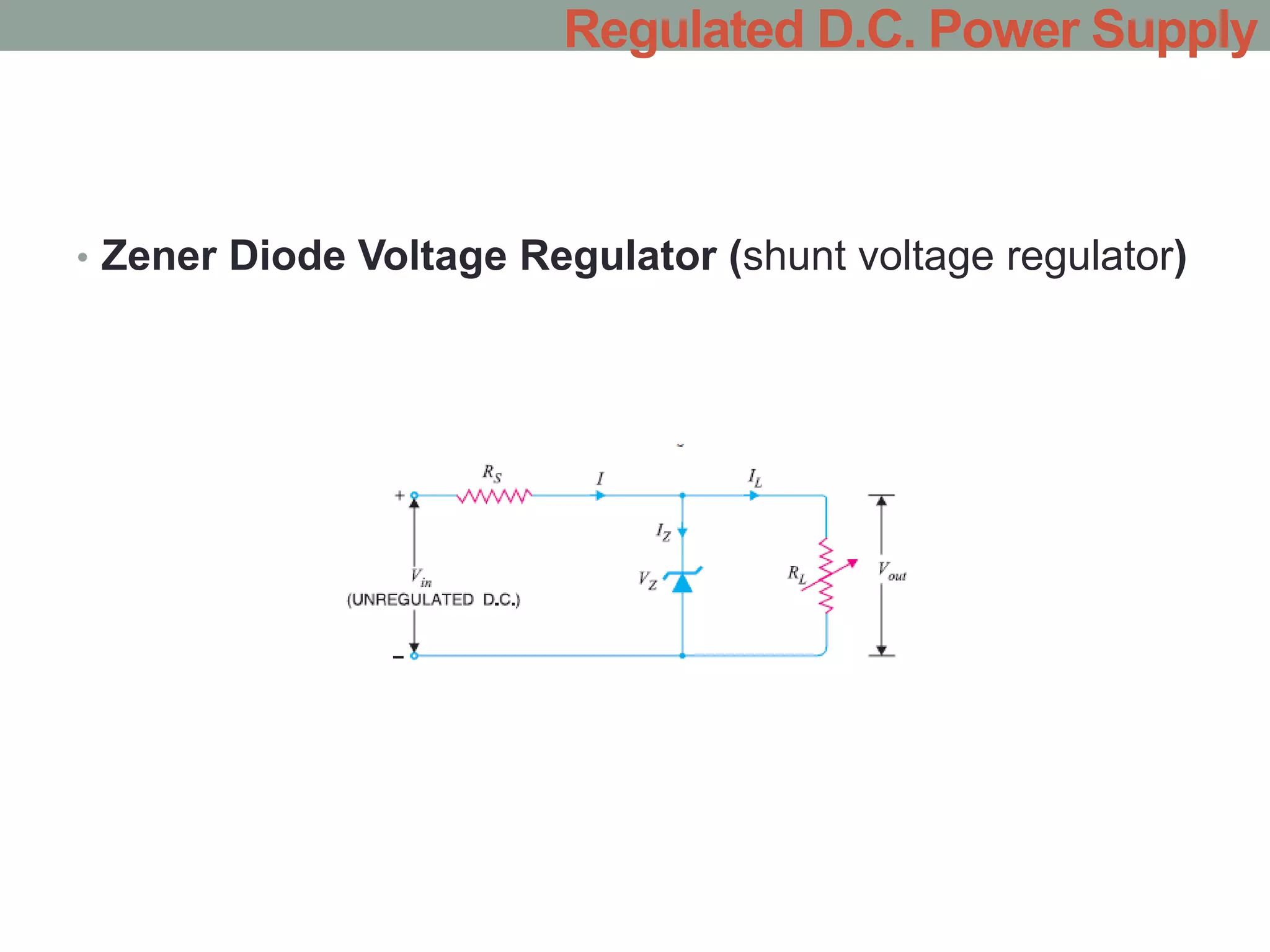
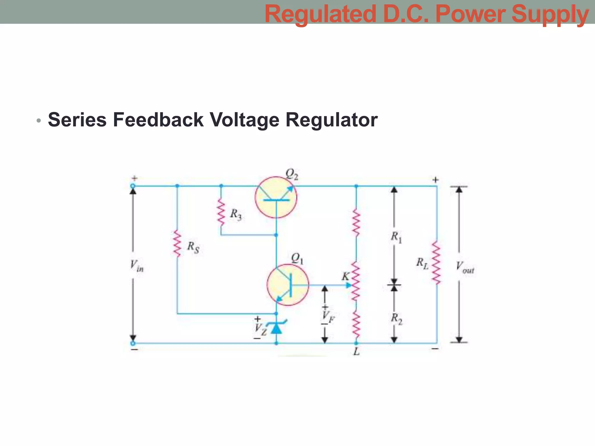
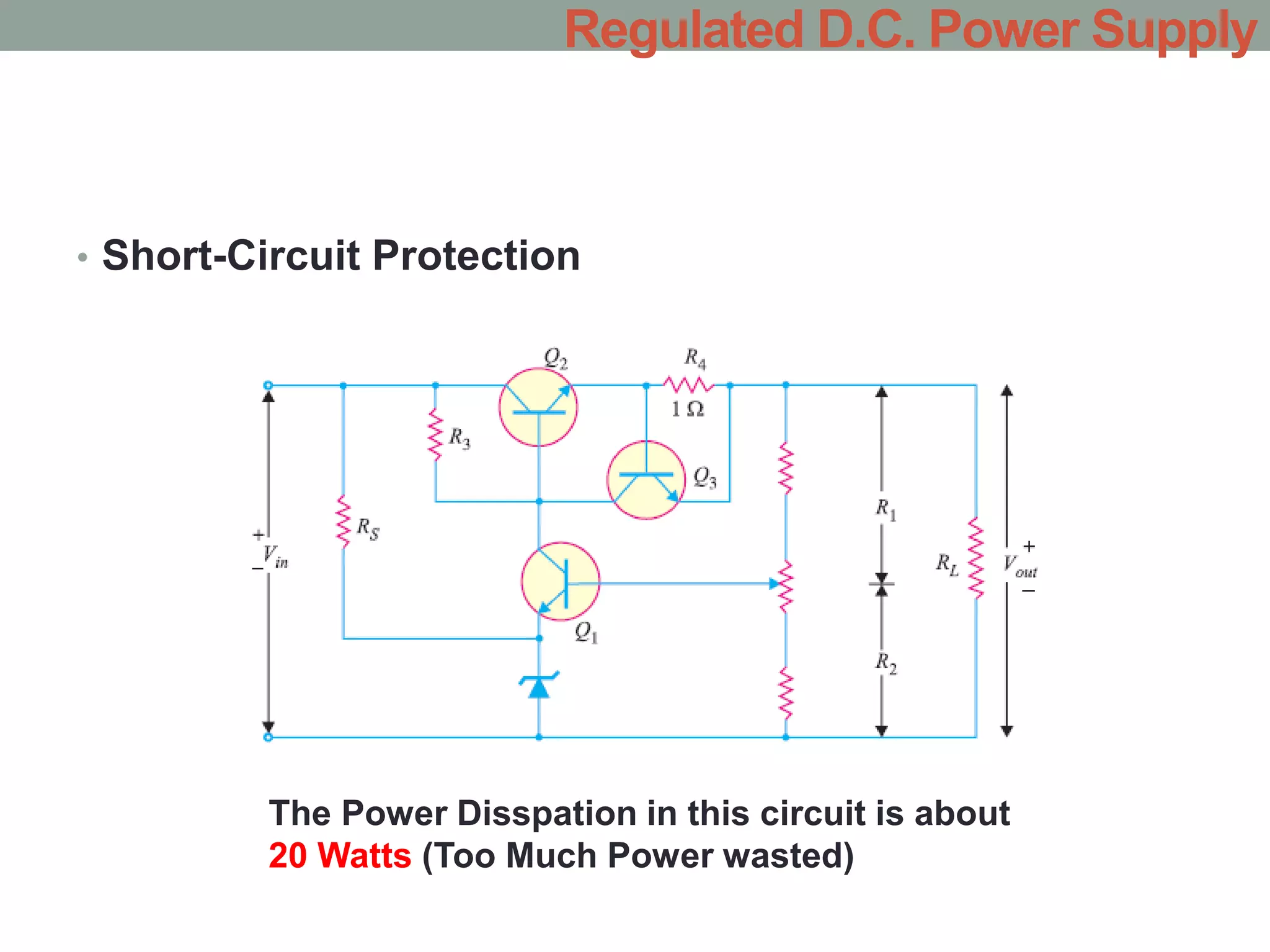
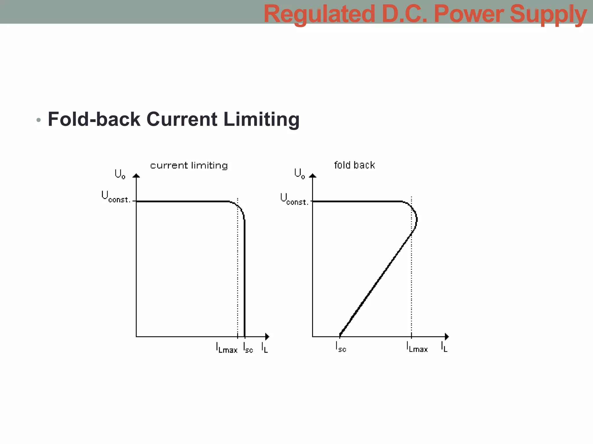
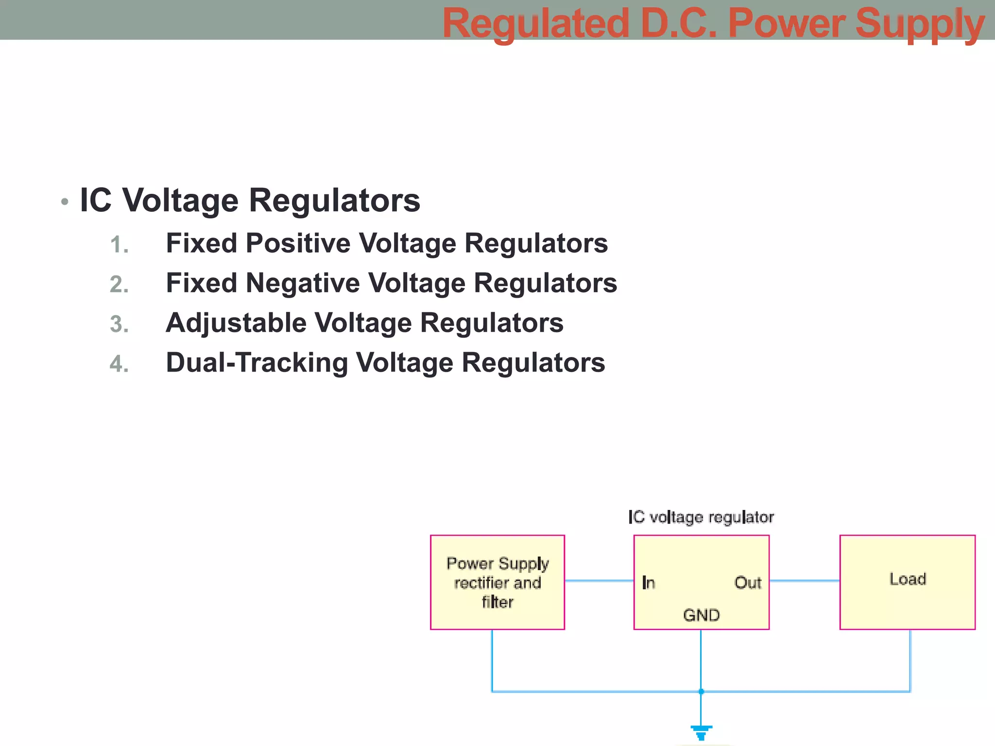
REGULATED D.C. POWER
SUPPLY
By:
Mohammed Al-Alaw
Regulated D.C. Power Supply
•Contents:
1. Ordinary D.C. Power Supply
2. Important Terms
3. Regulated Power Supply
4. Types of Voltage Regulators
5. Zener Diode Voltage Regulator
6. Conditions for Proper Operation of Zener Regulator
7. Transistor Series Voltage Regulator
8. Series Feedback Voltage Regulator
9. Short-Circuit Protection
10. Fold-back Current Limiting
11. Transistor Shunt Voltage Regulator
12. Shunt Feedback Voltage Regulator
13. I.C. Voltage Regulators (Commercial I.C.’s)
1. Fixed Positive Voltage Regulators
2. Fixed Negative Voltage Regulators
3. Adjustable Voltage Regulators
4. Dual-Tracking Voltage Regulators
• Ordinary D.C. Power Supply
Regulated D.C. Power Supply
• Important Terms
• Load Regulation
LR = V nl – V fl
% LR = (V nl – V fl) / V fl ≈ (V nl – V fl) / V nl
• Source Regulation
SR = V hl – V ll
%SR = (V hl – V ll) / V nom
Regulated D.C. Power Supply
• Output Impedance
Z out (CL) = Z out / (1 + AB)
• Ripple Rejection (usually referred in dB)
RR = V r(out) / V r(in)
dB RR = 20 log (V r(out) / V r(in) )
Regulated D.C. Power Supply
• Regulated Power Supply
Regulated D.C. Power Supply
• Limitations
A zener diode regulator has the following drawbacks :
1. It has low efficiency for heavy load currents. It is because if the
load current is large, there will be considerable power loss in the
series limiting resistance.
2. The output voltage slightly changes due to zener impedance as
Vout= Vz+ I zZ z. Changes in load current produce changes in
zener current. Consequently, the output voltage also changes.
Therefore, the use of this circuit is limited to only such applications
where variations in load current and input voltage are small.
Regulated D.C. Power Supply
• Types of Voltage Regulators
Regulated D.C. Power Supply
• Zener Diode Voltage Regulator (shunt voltage regulator)
Regulated D.C. Power Supply
• Conditions for Proper Operation of Zener Regulator
1. The zener must operate in the breakdown region or
regulating region i.e. between IZ (max) and IZ
(min). The current IZ (min) (generally 10 mA)
2. The zener should not be allowed to exceed
maximum dissipation power otherwise it will be
destroyed due to excessive heat.
3. There is a minimum value of RL to ensure that
zener diode will remain in the regulating region i.e.
breakdown region.
Regulated D.C. Power Supply
• Transistor Series Voltage Regulator
Vout = VZ − VBE
Regulated D.C. Power Supply
• Series Feedback Voltage Regulator
Regulated D.C. Power Supply
• Short-Circuit Protection
Let us consider the example as follows:
Regulated D.C. Power Supply
The input potential is
20 Volts, the output
potential is 10 Volts,
the load is 5 ohms this
would put the load
current 2 Amperes
resulting in the power
dissipated by the main
series Transistor to be
P = Vce x Ic
= (20 – 10) x 2
= 20 Watts
Which means a huge
heat sink
20 V
+
10
-
5Ω
So This valuable transistor
needs Short-Circuit Protection
• Short-Circuit Protection
Current Limitting Circuit
Regulated D.C. Power Supply
The Power Disspation in this circuit is about
20 Watts (Too Much Power wasted)
• Fold-back Current Limiting
Regulated D.C. Power Supply
•
Regulated D.C. Power Supply
In This Case we may
Make the power less to
about %50 less or even
more
• Transistor Shunt Voltage Regulator
Vout = Vz + VBE
A shunt voltage
regulator provides
regulation
by shunting (passing)
current away from the
load to regulate the
output voltage.
Regulated D.C. Power Supply
• Drawbacks. A shunt voltage regulator has the following
drawbacks :
1. A large portion of the total current through RS flows
through transistor rather than to the load resulting in a
considerable power loss in RS.
2. There are problems of overvoltage protection in this
circuit.
For these reasons, a series voltage regulator is preferred
over the shunt voltage regulator.
Regulated D.C. Power Supply
• Shunt Feedback Voltage Regulator
Regulated D.C. Power Supply
• IC Voltage Regulators
1. Fixed Positive Voltage Regulators
2. Fixed Negative Voltage Regulators
3. Adjustable Voltage Regulators
4. Dual-Tracking Voltage Regulators
Regulated D.C. Power Supply
• IC Voltage
Regulators
Regulated D.C. Power Supply
• IC Voltage Regulators
1. Fixed Positive Voltage Regulators
Regulated D.C. Power Supply
Reference Voltage
Sampling
Circuit
Comparator
Regulated D.C. Power Supply
• IC Voltage Regulators
2. Fixed Negative Voltage Regulators
Regulated D.C. Power Supply
• IC Voltage Regulators
3. Adjustable Voltage Regulators
Vout = 1.25 ( ( R2 / R1) + 1)
Regulated D.C. Power Supply
Example. In Fig. R2 is adjusted to 2.4 kΩ. Determine the regulated
D.C. output voltage for the circuit.
Solution. The regulated D.C. output voltage for the circuit is
given by ;
Regulated D.C. Power Supply
• IC Voltage Regulators
4. Dual-Tracking Voltage Regulators
Regulated D.C. Power Supply
Thank You

Regulated_Power.ppt

  • 1.
  • 2.
    Regulated D.C. PowerSupply •Contents: 1. Ordinary D.C. Power Supply 2. Important Terms 3. Regulated Power Supply 4. Types of Voltage Regulators 5. Zener Diode Voltage Regulator 6. Conditions for Proper Operation of Zener Regulator 7. Transistor Series Voltage Regulator 8. Series Feedback Voltage Regulator 9. Short-Circuit Protection 10. Fold-back Current Limiting 11. Transistor Shunt Voltage Regulator 12. Shunt Feedback Voltage Regulator 13. I.C. Voltage Regulators (Commercial I.C.’s) 1. Fixed Positive Voltage Regulators 2. Fixed Negative Voltage Regulators 3. Adjustable Voltage Regulators 4. Dual-Tracking Voltage Regulators
  • 3.
    • Ordinary D.C.Power Supply Regulated D.C. Power Supply
  • 4.
    • Important Terms •Load Regulation LR = V nl – V fl % LR = (V nl – V fl) / V fl ≈ (V nl – V fl) / V nl • Source Regulation SR = V hl – V ll %SR = (V hl – V ll) / V nom Regulated D.C. Power Supply
  • 5.
    • Output Impedance Zout (CL) = Z out / (1 + AB) • Ripple Rejection (usually referred in dB) RR = V r(out) / V r(in) dB RR = 20 log (V r(out) / V r(in) ) Regulated D.C. Power Supply
  • 6.
    • Regulated PowerSupply Regulated D.C. Power Supply
  • 7.
  • 8.
    • Limitations A zenerdiode regulator has the following drawbacks : 1. It has low efficiency for heavy load currents. It is because if the load current is large, there will be considerable power loss in the series limiting resistance. 2. The output voltage slightly changes due to zener impedance as Vout= Vz+ I zZ z. Changes in load current produce changes in zener current. Consequently, the output voltage also changes. Therefore, the use of this circuit is limited to only such applications where variations in load current and input voltage are small. Regulated D.C. Power Supply
  • 9.
    • Types ofVoltage Regulators Regulated D.C. Power Supply
  • 10.
    • Zener DiodeVoltage Regulator (shunt voltage regulator) Regulated D.C. Power Supply
  • 11.
    • Conditions forProper Operation of Zener Regulator 1. The zener must operate in the breakdown region or regulating region i.e. between IZ (max) and IZ (min). The current IZ (min) (generally 10 mA) 2. The zener should not be allowed to exceed maximum dissipation power otherwise it will be destroyed due to excessive heat. 3. There is a minimum value of RL to ensure that zener diode will remain in the regulating region i.e. breakdown region. Regulated D.C. Power Supply
  • 12.
    • Transistor SeriesVoltage Regulator Vout = VZ − VBE Regulated D.C. Power Supply
  • 13.
    • Series FeedbackVoltage Regulator Regulated D.C. Power Supply
  • 14.
  • 15.
    • Short-Circuit Protection Letus consider the example as follows: Regulated D.C. Power Supply The input potential is 20 Volts, the output potential is 10 Volts, the load is 5 ohms this would put the load current 2 Amperes resulting in the power dissipated by the main series Transistor to be P = Vce x Ic = (20 – 10) x 2 = 20 Watts Which means a huge heat sink 20 V + 10 - 5Ω So This valuable transistor needs Short-Circuit Protection
  • 16.
    • Short-Circuit Protection CurrentLimitting Circuit Regulated D.C. Power Supply The Power Disspation in this circuit is about 20 Watts (Too Much Power wasted)
  • 17.
    • Fold-back CurrentLimiting Regulated D.C. Power Supply
  • 18.
    • Regulated D.C. PowerSupply In This Case we may Make the power less to about %50 less or even more
  • 19.
    • Transistor ShuntVoltage Regulator Vout = Vz + VBE A shunt voltage regulator provides regulation by shunting (passing) current away from the load to regulate the output voltage. Regulated D.C. Power Supply
  • 20.
    • Drawbacks. Ashunt voltage regulator has the following drawbacks : 1. A large portion of the total current through RS flows through transistor rather than to the load resulting in a considerable power loss in RS. 2. There are problems of overvoltage protection in this circuit. For these reasons, a series voltage regulator is preferred over the shunt voltage regulator. Regulated D.C. Power Supply
  • 21.
    • Shunt FeedbackVoltage Regulator Regulated D.C. Power Supply
  • 22.
    • IC VoltageRegulators 1. Fixed Positive Voltage Regulators 2. Fixed Negative Voltage Regulators 3. Adjustable Voltage Regulators 4. Dual-Tracking Voltage Regulators Regulated D.C. Power Supply
  • 23.
  • 24.
    • IC VoltageRegulators 1. Fixed Positive Voltage Regulators Regulated D.C. Power Supply
  • 25.
    Regulated D.C. PowerSupply Reference Voltage Sampling Circuit Comparator
  • 26.
  • 27.
    • IC VoltageRegulators 2. Fixed Negative Voltage Regulators Regulated D.C. Power Supply
  • 28.
    • IC VoltageRegulators 3. Adjustable Voltage Regulators Vout = 1.25 ( ( R2 / R1) + 1) Regulated D.C. Power Supply
  • 29.
    Example. In Fig.R2 is adjusted to 2.4 kΩ. Determine the regulated D.C. output voltage for the circuit. Solution. The regulated D.C. output voltage for the circuit is given by ; Regulated D.C. Power Supply
  • 30.
    • IC VoltageRegulators 4. Dual-Tracking Voltage Regulators Regulated D.C. Power Supply
  • 31.
  • 32.
    Regulated D.C. PowerSupply Thank You