Downloaded 66 times
![Optical Communication Systems
4
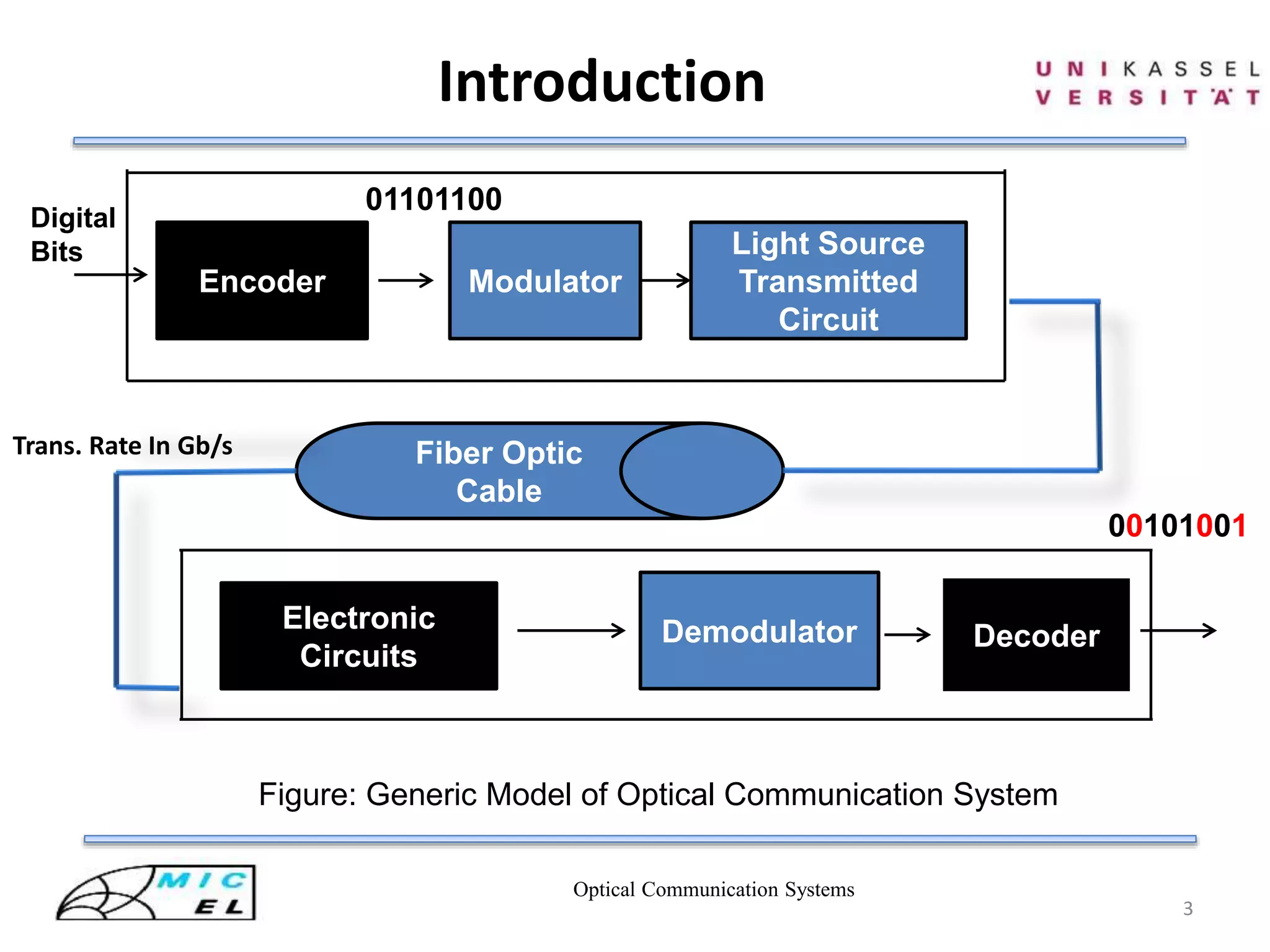
Figure : Block diagram of MLSE based receiver of OC-192 fiber links
Electronic Circuits for Conversion
9.9Gbps
Viterbi Decoding
Ref [3]](https://image.slidesharecdn.com/viterbidecoderinopticalcommsystem-140807031314-phpapp02/75/Viterbi-decoder-in-optical-comm-system-4-2048.jpg)
![Optical Communication Systems
6
Convolutional Encoder
mj-2mj-1mj X1 X2
Shift Register
Encoded Bits
Figure: (2,1,2)bit Convolutional Encoder
Operation
I/P P/S N/
S
X1=mj
+mj-2
X2=mj+mj-1
+mj-2
O/P
0 0 0 00 0+0=0 0+0+0=0 00
1 0 0 10 1+0=1 1+0+0=1 11
0 0 1 00 0+1=1 0+0+1=1 11
1 0 1 10 1+1=0 1+0+1=0 00
0 1 0 01 0+0=0 0+1+0=1 01
1 1 0 11 1+0=1 1+1+0=0 10
0 1 1 01 0+1=1 0+1+1=0 10
1 1 1 11 1+1=0 1+1+1=1 01
P/S:Present State
N/S:New State
I/P:Input
O/P:Output
1 00 0 1
0 1
[2]](https://image.slidesharecdn.com/viterbidecoderinopticalcommsystem-140807031314-phpapp02/75/Viterbi-decoder-in-optical-comm-system-6-2048.jpg)
![Optical Communication Systems
7
Trellis Diagram
I/P P/S N/S O/P
0 0 0 00 00
1 0 0 10 11
0 0 1 00 11
1 0 1 10 00
0 1 0 01 01
1 1 0 11 10
0 1 1 01 10
1 1 1 11 01
00
01
10
11
00
01
10
11
I/P: 0
1
00
11
11
00
01
10
10
01
Figure: Trellis diagram for (2,1,2) convolutional code
[2]](https://image.slidesharecdn.com/viterbidecoderinopticalcommsystem-140807031314-phpapp02/75/Viterbi-decoder-in-optical-comm-system-7-2048.jpg)
![Recent Advancement
Optical Communication Systems
12
Lazy Viterbi Algorithm
• Applicable for both block and convolutional code
• Much faster compare to original one
• Running time does not depend on the constraint length
• Algorithms work by not expanding any nodes until
it really needs to
Practically found:
Code with constraint length 6,the Lazy algorithm is about 50% faster
than normal Viterbi Algorithm when SNR > 6 dB
Ref [4]](https://image.slidesharecdn.com/viterbidecoderinopticalcommsystem-140807031314-phpapp02/75/Viterbi-decoder-in-optical-comm-system-12-2048.jpg)

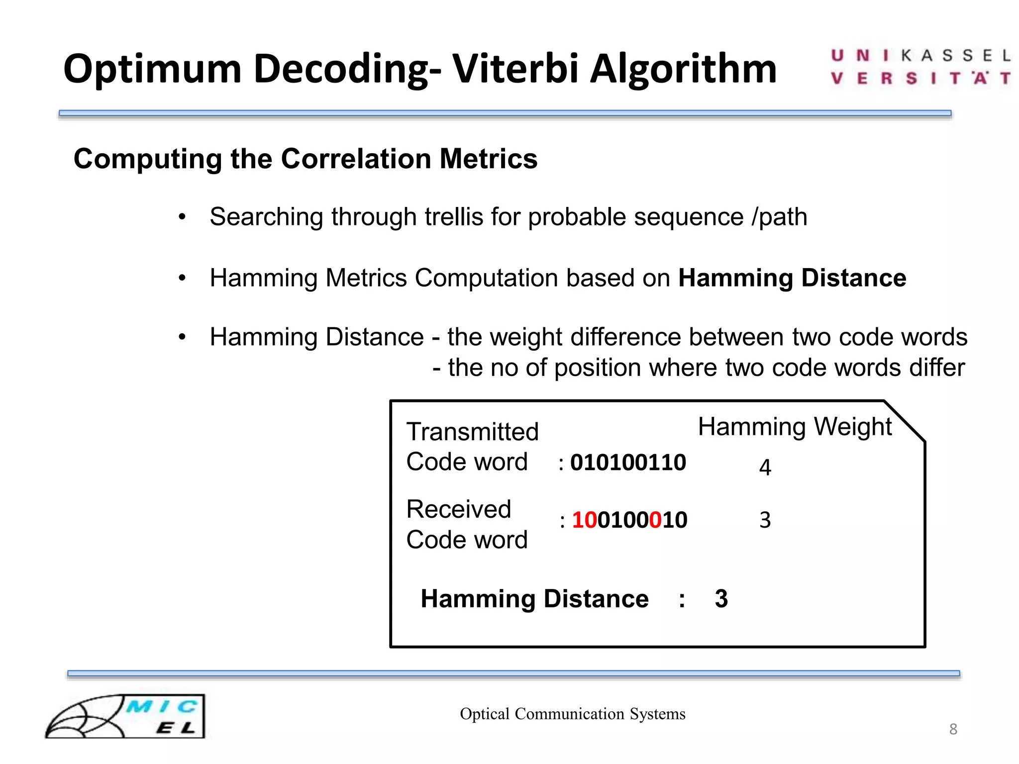
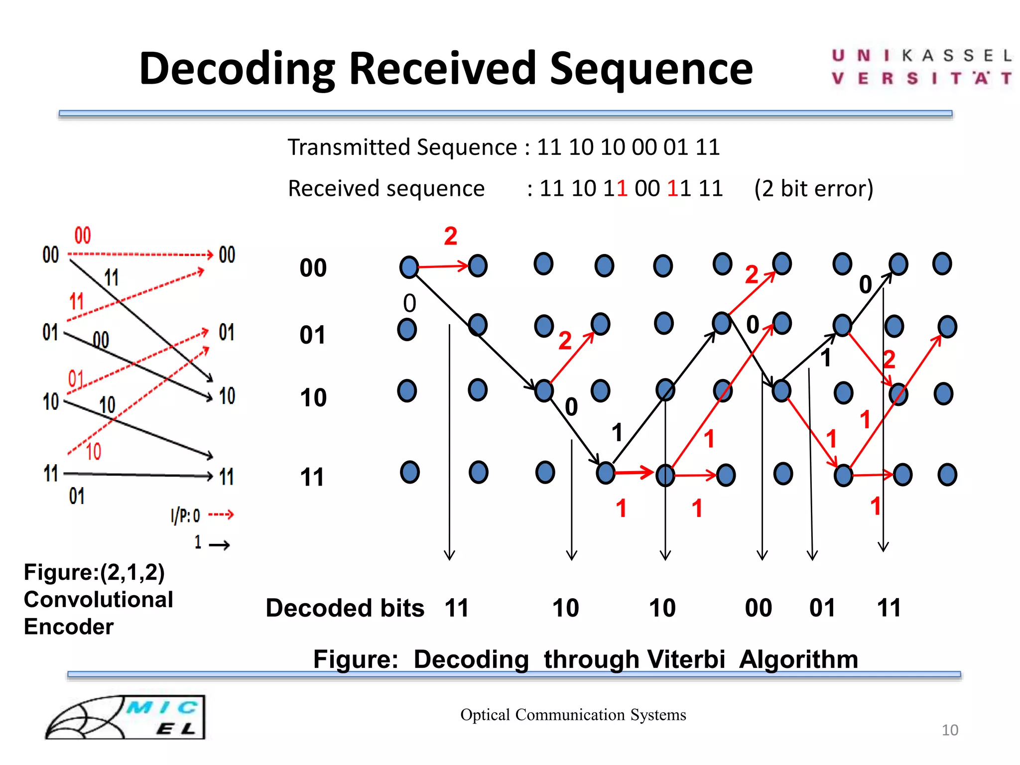
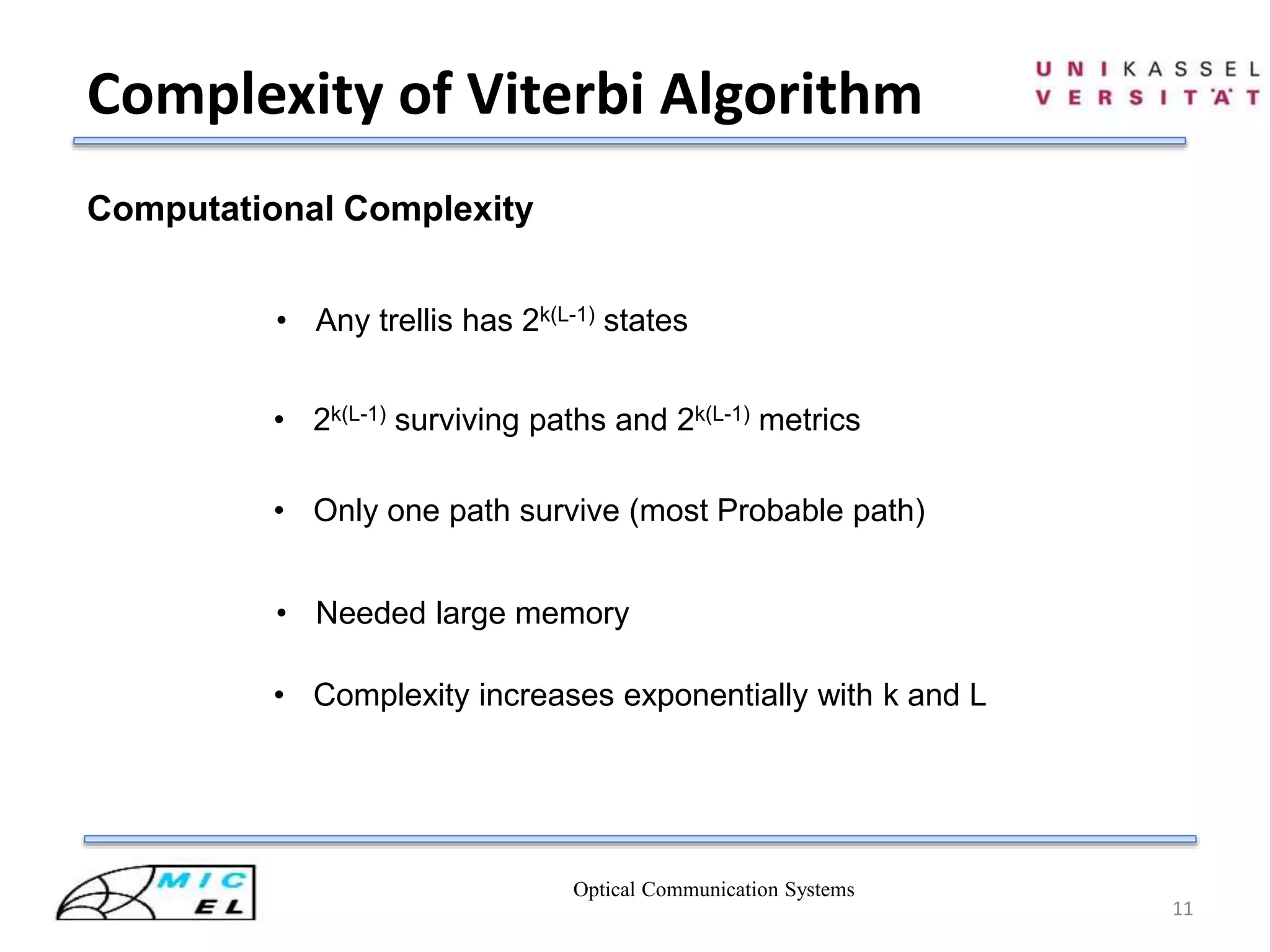
This document discusses Viterbi decoding in optical communication systems. It begins with an introduction and overview. It then covers electronic circuits for conversion, convolutional encoding including trellis diagrams, and the Viterbi algorithm for optimum decoding including computing metrics, path selection, and decoding a received sequence. It discusses the complexity of the Viterbi algorithm and recent advances like lazy Viterbi. In the end it provides a summary and references.