This paper introduces an improved Viterbi decoder utilizing a window system, achieving a 1 dB performance gain over the classical Viterbi decoder when evaluated over Gaussian channels. It presents the underlying theory of Trellis Coded Modulation (TCM) and compares various decoding algorithms including classical Viterbi, MAP, and their variants. Additionally, a function named rscpoly2trellis for creating the trellis structure of a Recursive Systematic Convolutional encoder is proposed and evaluated.
![International Journal of Electrical and Computer Engineering (IJECE)
Vol. 8, No. 1, February 2018, pp. 611~621
ISSN: 2088-8708, DOI: 10.11591/ijece.v8i1.pp611-621 611
Journal homepage: http://iaescore.com/journals/index.php/IJECE
Improving The Performance of Viterbi Decoder using Window
System
Rekkal Kahina, Abdesselam Bassou
Department of Electrical Engineering, Faculty of Technology, Tahri Mohammed University-Bechar, Algeria
Article Info ABSTRACT
Article history:
Received Aug 18, 2017
Revised Dec 28, 2017
Accepted Jan 12, 2018
An efficient Viterbi decoder is introduced in this paper; it is called Viterbi
decoder with window system. The simulation results, over Gaussian
channels, are performed from rate 1/2, 1/3 and 2/3 joined to TCM encoder
with memory in order of 2, 3. These results show that the proposed scheme
outperforms the classical Viterbi by a gain of 1 dB. On the other hand, we
propose a function called RSCPOLY2TRELLIS, for recursive systematic
convolutional (RSC) encoder which creates the trellis structure of a recursive
systematic convolutional encoder from the matrix “H”. Moreover, we present
a comparison between the decoding algorithms of the TCM encoder like
Viterbi soft and hard, and the variants of the MAP decoder known as BCJR
or forward-backward algorithm which is very performant in decoding TCM,
but depends on the size of the code, the memory, and the CPU requirements
of the application.
Keyword:
Log-MAP
MAP
Max-Log-Map
TCM
TCM-UGM
Viterbi soft
Viterbi with window system
Viterbi hard
Copyright © 2018 Institute of Advanced Engineering and Science.
All rights reserved.
Corresponding Author:
Rekkal Kahina,
Department of Electrical Engineering,
Faculty of Technology,
Tahri Mohammed University-Bechar,
B.P 417 University Tahri Mohammed Bechar County Algeria.
Email: rekkal@yahoo.fr
1. INTRODUCTION
The spectrum of frequencies is a very limited and in demand resource. Its distribution is severely
regulated by the International Telecommunication Union. That is why one of the most important objective in
the design of a digital communication system is the maximum exploitation of the available spectrum.
Traditionally, coding and modulation have been considered as two separate entities [1]. In 1982, the work
presented by Ungerboeck [2] showed that a joint optimization of the coding and the modulation was possible:
the trellis coded modulation or TCM, which is based on the same principle as the block-coded modulation,
but is of infinite dimension. The transmitted data forms semi-infinite or infinite sequences. The principle
stated by Forney applies equally to modulations encoded in trellis and modulations coded in blocks.
Nevertheless, trellis-coded modulations do not lead to elements of a network of points, since their dimensions
are infinite. They are based on the partition of classical constellations (PSK or QAM) into subsets of higher
minimum distance. Transitions from one subset to another are made in a convolutional code. The gain in
terms of minimum distance must exceed the loss in terms of the number of useful bits per symbol so that the
coded modulations are more efficient than the conventional ones.
In the first part of this work, we present the basic theory of trellis coded modulation. In the second
part, we present the algorithms of decoding TCM encoder by classical Viterbi, MAP and its variants Log-
MAP, max-log-Map decoder, and we present our proposed Viterbi which is improved by the window system.
In addition, we also present a comparison between Viterbi soft and hard decoders shown over AWGN
channel. To close this part we present the simulation which has been done using MATLAB program and the](https://image.slidesharecdn.com/v6628dec188aug8311iaespaperrevised2editern-201106062510/85/Improving-The-Performance-of-Viterbi-Decoder-using-Window-System-1-320.jpg)
![ ISSN: 2088-8708
Int J Elec & Comp Eng, Vol. 8, No. 1, February 2018 : 611 – 621
612
results as seen in AWGN channel with 2, 3 memories. In the third part, we propose a function which is called
RSCPOLY2TRELLIS for recursive systematic convolutional (RSC) encoder which creates the trellis
structure of a recursive systematic convolutional encoder from the matrix “H” and we present a simulation of
the comparison between RSC TCM, 8PSK with Viterbi soft, MAP, Log-Map, and Max-log-map. Finally, the
last section presents the conclusion of this paper.
2. RELATED WORKS
In this section, we present some related works which had used the decoding algorithms: Viterbi,
MAP, and Log-Map moreover the encoder TCM with Ungerboeck mapping and Gray code mapping (UGM).
In [3], Manish Kumar and al had made a comparison in the latency performance of the RSC-RSC
serial concatenated code using non-iterative concatenated Viterbi decoding to RS-RSC serial concatenated
system codes using concatenation of Viterbi & Berklelamp-Massey decoding. The simulation results had
shown that by increasing the code rate, the latency decreases & RSC-RSC is to be a better code rather than
RS-RSC which has low latency. Hence RSC-RSC system is more suiTable for low latency applications.
In [4], Ilesanmi Banjo Oluwafemi improve the performance of two hybrid concatenated Super-
Orthogonal Space-Time Trellis Codes « SOSTTC » topologies over flat fading channels. The encoding
operation is based on the concatenation of convolutional codes, interleaving, and super-orthogonal space-
time trellis codes and the decoding of these two schemes were done by applying iterative decoding process
were the symbol-by-symbol maximum a posteriori (MAP) decoder is used for the inner SOSTTC decoder
and a bit-by-bit MAP decoder is used for the outer convolutional decoder.
In [5], the work of Sameer A Dawood and al had shown the effectiveness of turbo codes to develop
a new approach for an OFDM system based on a Discrete Multiwavelet Critical-Sampling Transform
(OFDM-DMWCST). They used of turbo coding in an OFDM-DMWCST system is useful in providing the
desired performance at higher data rates. Two types of turbo codes were used in this work, i.e., Parallel
Concatenated Convolutional Codes (PCCCs) and Serial Concatenated Convolutional Codes (SCCCs). In both
types, the decoding is performed by the iterative decoding algorithm based on the log-MAP (Maximum A
posteriori) algorithm.
In [6], Bassou and Djebbari introduced a new type of mapping called the Ungerboeck gray trellis
coded modulation (TCM-UGM) for spectral efficiency greater than or equal to 3 bits/s/Hz. This TCM-UGM
code outperforms the performance of Ungerboeck TCM code by 0.26 dB over Gaussian channel and 2.59 dB
over Rayleigh fading channel at BER = 10-5. This technique is combined with our approach to getting more
efficiency.
In [7], Trio and al had proposed a VLSI architecture to implement reversed-trellis TBCC (RT-
TBCC) algorithm. This algorithm is designed by modifying direct-terminating maximum-likelihood (ML)
decoding process to achieve better correction rate which reduces the computational time and resources
compared to the existing solution.
3. TCM : TRELLIS CODED MODULATION
According to Ungerboeck in 1982, whatever the spectral efficiency considered for the transmission
and for a code as complex as it can be, the asymptotic gain of coding given by a TCM is almost maximal
using a single binary element of redundancy per symbol transmitted. Thus, for a TCM constructed from a
constellation with M = 2n+1 points, the spectral efficiency of the transmission is n bits / s / Hz and the
performances of the TCM are compared with those of a modulation to 2n states; that is to say, having a 2-
point constellation. The constellation of a TCM, therefore, has twice as many points as that of the uncoded
modulation having the same spectral efficiency.
Suppose, therefore, that we want to transmit a block of n binary elements coming from the source of
information. It is divided into two blocks of respective lengths, ñ and (n-ñ). The length of ñ block is then
coded with a convolution encoder performance Rc = to v memories (2V states); the second block is
unchanged. The (ñ + 1) bits from the encoder are then used to select a sub-constellation 2n-ñ point while the
(n-ñ) uncoded bits are used to select a particular item in this sub-constellation.
Figure 1 shows the synoptic diagram of an encoder for Ungerboeck TCM.](https://image.slidesharecdn.com/v6628dec188aug8311iaespaperrevised2editern-201106062510/85/Improving-The-Performance-of-Viterbi-Decoder-using-Window-System-2-320.jpg)
![Int J Elec & Comp Eng ISSN: 2088-8708
Improving The Performance Of Viterbi Decoder using Window System (Rekkal Kahina)
613
Figure 1. Synoptic diagram of an encoder for Ungerboeck TCM
3.1. Rules for Building the Trellis
The implementation of the decoder requires the construction of a trellis of the TCM. To build such a
trellis, some rules must be followed if one wishes to maximize the free distance. For this, Ungerboeck
proposes the following three rules:
The M =2n+1 signals of the initial (unpartitioned) constellation must be used with the same
frequency. Figure 2 shows the set Partitioning method applied to the 8PSK [2]
Figure 2. Set Partitioning method applied to the 8PSK [2]
The 2n-ñ parallel branches, if they exist, must be associated with signals belonging to the same 2n-ñ
sub-constellation.
The 2n branches that leave a state or reach a state must be associated with signals belonging to the
same 2n point sub-constellation.
The first rule provides the trellis with a regular pattern. Rules 2 and 3 ensure that the free distance of
the TCM is always greater than the minimum Euclidean distance of the uncoded modulation taken as
reference for the coding gain calculation.
Thus the asymptotic coding gain is:
Ga = 10 log10 ( ) (1)
4. ALGORITHMS OF DECODING TCM ENCODER
The most common decoding is based on the Viterbi algorithm [8]. It consists in finding in the tree
the path which corresponds to the most probable sequence, that is to say, that which is at the minimum
distance of received sequence or the most probable sequence. The following section illustrates the Viterbi
and MAP algorithms.](https://image.slidesharecdn.com/v6628dec188aug8311iaespaperrevised2editern-201106062510/85/Improving-The-Performance-of-Viterbi-Decoder-using-Window-System-3-320.jpg)
![ ISSN: 2088-8708
Int J Elec & Comp Eng, Vol. 8, No. 1, February 2018 : 611 – 621
614
4.1. Algorithm of Viterbi
The aim of the maximum likelihood decoding is to look in the trellis code “C” the nearest road
(most likely) of the received sequence (i.e. observation). The distance employed in the algorithm is either the
Euclidean distance, in the case of soft-input, or the hamming distance, in the case of farms inputs.
Thus the decoding problem is: given ( per trellis interval, where determine the
most likely transmitted path through the trellis. If we assume that the uses of the BSC (the binary symmetric
channel) are independent (i.e., we have random errors), the problem reduces to minimizing the Hamming
distance between the { } and our estimate of the{ }, denoted as {̂} :
e ( ̂) = ∑ ∑ ̂ (2)
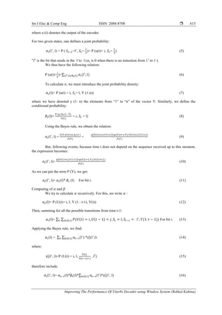
Figure 3. Transition diagram for Viterbi algorithm
A list of all the transition per state and their values for ( ̂ ̂ ̂ ) are given in Figure 3. For
each trellis transition we do the following. Let , = be the accumulated state metric, that is,
the sum in (1) up to trellis interval i; the input for the discrete time transition is ( )
for each state, :
a) Compute
̂ ̂ ̂ [ ∑ ̂ ] (3)
b) Call the best ̂ ̂ ̂ the winning transition and store it as well as M ( ), the state
metric for the winning transition.
When these steps are implemented, we are left with one single transition path per state, per trellis
interval. The collections of these winning transition paths over time are called survivor paths. The decoding
path is then the minimum of overall survivor paths. In reality, one should wait until survivor paths
merge, that is, when their initial segments coincide. In practice, one stores the result for trellis intervals
and then makes the choice of the best survivor path; that is the path with the smallest m (.).
The Viterbi algorithm, therefore, requires the computation of 2kl metrics at each step t, hence a
complexity of W ˟ , linear in W. However, the complexity remains exponential in k and L, which limits the
use of the codes of small size (k L of 7 to 10 maximum). The width W of the decoding window is taken in
practice to about 5L. This guarantees (empirically) that the survivors converge to a single path inside the
decoding window. The Viterbi algorithm, therefore, requires the storage of cumulative metrics and
survivors of length 5kL bits [9].
4.2. Algorithm of MAP
This algorithm is based on the calculation of the probability of occurrence of a bit (1 or 0) in a
certain position. We have at our disposal a string of length T, which comes from the coding of an information
word of size . The method consists in calculating iteratively the a posteriori probability of each bit, first as a
function of the values of the probabilities for the bits preceding it, and then as a function of the posterior bits.
For this reason, the algorithm is called "forward-backward algorithm". We place equal importance on the
"before" bits and the "after" bits.
Here, Y is the string of bits received and t is the position of the bit in the string. Similarly, we have
denoted , the set of transitions from state to state , as soon as we have had the bit „i‟ at
the input. Let M be the number of possible states.
We try to calculate the log-likelihood ratio logarithm value (λ (u (t)) (log-likelihood ratio) :
(u(t)) = ln [ ] (4)](https://image.slidesharecdn.com/v6628dec188aug8311iaespaperrevised2editern-201106062510/85/Improving-The-Performance-of-Viterbi-Decoder-using-Window-System-4-320.jpg)
![ ISSN: 2088-8708
Int J Elec & Comp Eng, Vol. 8, No. 1, February 2018 : 611 – 621
616
by similar calculations, we obtain:
(l)= ∑ ∑ { } (l‟)* (l‟, l) (17)
as characterizes the noise, which is white Gaussian, one can write:
(l‟,l )= P (U (t) =i)* exp (
‖ ‖
) if (l‟, l) (t) 0 if not (18)
Here x (t) is the value that should have been at the output of the encoder, as soon as the state is
changed from state to state.
4.3. Simplified versions of the MAP algorithm
The BCJR algorithm, or MAP, suffers from one important disadvantage: it must carry out many
multiplications. In order to reduce this computational complexity, several simplified versions were
introduced as (SOVA) in 1989 [10], the max-log-MAP algorithm 1990-1994 [11], [12], and the log-MAP
algorithm in 1995 [13]. The multiplication operations are replaced by the addition, and three new variables
are defined as A, B and Γ, as following:
Γk (s‟,s)=ln γk(s‟,s) = ln Ck + ∑
{
{
where
{
( | |
)
(19)
For the convolutional encoder of rate , we use the symbol by symbol MAP Algorithm for non-
binary trellises. Roughly speaking, we can state that the complexity of the BCJR algorithm is about three
times that of the Viterbi algorithm.
5. THE PROPOSED APPROACH
5.1. Viterbi Improved by Window System
We saw in the previous sections how it was possible, using an algorithm, to correct an erroneous
message. In this part, we talk about methods of encoding and decoding information that requires some
computing power, which can cause some problems (for example in embedded systems where there is limited
computing power and the calculation must be done in real time). Finally, only low error percentage messages
(encoded without errors) can be corrected upon receipt. For this purpose, it is proposed in our approach to
using the window system in the encoding and decoding phase of the information in order to minimize the
error on a single window whose length equal to the number of memory plus 1.
In this section, we use the window in convolutional coding and decoding. To explain the difference
between the window system and the classical approach, we choose to present the following example:
Figure 4 shows the structure of the convolutional encoder with rate R=1/2.
Figure 4. Diagram of a convolutional encoder of output](https://image.slidesharecdn.com/v6628dec188aug8311iaespaperrevised2editern-201106062510/85/Improving-The-Performance-of-Viterbi-Decoder-using-Window-System-6-320.jpg)
![Int J Elec & Comp Eng ISSN: 2088-8708
Improving The Performance Of Viterbi Decoder using Window System (Rekkal Kahina)
617
In Table 1 we see that "Y" is a function which depends on the input X and the values of states S0, S1 (X, S0,
S1) [Yi = F (Xi, S0, S1)].
Initialization on values of S0 = 0; S1 = 0;
Figure 5 shows the transmission chain of convolution encoder.
Figure 5. Transmission chain of convolution encoder
Table 1. Scenarios of coding
Xi x0 x1 x2 x3 x4 x5 x6 x7 x8
(F)
Xi
S0
S1
x0
0
0
x1
x0
0
x2
x1
x0
x3
x2
x1
x4
x3
x2
x5
x4
x3
x6
x5
x4
x7
x6
x5
x8
x7
x6
Yi y0 y1 y2 y3 y4 y5 y6 y7 y8
According to Table 1, we can distinguish that most of the “Xi” survive on many “Yi” by the size of
the constraint of the code (in our case, the size of the constraint equals three (03)).
That is to say that the code y0, for its encoding, depend on “X0, S0, S1”, y1 depending on “X1, X0,
S1”, and the code y2 depends on “X2, X1, X0”. Hence, we see that X0 appears three times for the encoding
of “Y0, Y1, and Y2”.
The disadvantage of this phenomenon is the decoding by the VITERBI algorithm. If all the bits of
"Yi" are erroneous, the algorithm decodes a "Xi" erroneous, and this error expands on the size of the
constraint of the code and consequently, all that follows is wrong. To overcome this phenomenon we
propose the window on the size of the constraint of the code as indicated in Table 2.
a. The size of the constraint is 3 (it is the number of memory +1).
Initialization: S0 = 0; S1 = 0;
b. If all the bits of a "Yi" are erroneous, the algorithm decodes a "Xi "wrong, but only on a window.
Table 2. Convolutional encoding by the window system
Figure 6 shows a transmission chain of a convolutional encoder under the constraint length.](https://image.slidesharecdn.com/v6628dec188aug8311iaespaperrevised2editern-201106062510/85/Improving-The-Performance-of-Viterbi-Decoder-using-Window-System-7-320.jpg)
![ ISSN: 2088-8708
Int J Elec & Comp Eng, Vol. 8, No. 1, February 2018 : 611 – 621
618
Figure 6. A transmission chain of a convolutional encoder under the constraint length
5.2. RSCpoly2trellis for Recursive Systematic Convolutional (RSC) Encoder
The proposed function RSCpoly2trellis Syntax: Trellis = RSCpoly2trellis (H);
Where RSCpoly2trellis function accepts a polynomial description of a recursive systematic
convolutional (RSC) encoder and returns the corresponding trellis structure description. The output of
RSCpoly2trellis is suiTable as an input to the convenc and vitdec functions and as a mask parameter for the
Convolutional Encoder, Viterbi Decoder in the Communications Block.
Figure 7 shows the recursive systematic convolutional encoder with rate which is represented by
the matrix H:
[ ]
Figure 7. Recursive systematic convolutional encoder with rate
We describe the function which creates the trellis structure of a recursive systematic convolutional
encoder from the matrix H.
We have those parameters:
a. Number of input symbols : numInputSymbols) which equal to 2(The sum of the rows of the matrix
H) -1
b. Number of output symbols : (numOutputSymbols) which equal to 2(The sum of the rows of the
matrix H)
c. Number of states (numState) which equal to 2(The sum of the columns of the matrix H) -1
d. Matrix of next states (nextState) which has a dimension of 2numStatesx2numInputSymbols and
next state equals to :
{](https://image.slidesharecdn.com/v6628dec188aug8311iaespaperrevised2editern-201106062510/85/Improving-The-Performance-of-Viterbi-Decoder-using-Window-System-8-320.jpg)
![ ISSN: 2088-8708
Int J Elec & Comp Eng, Vol. 8, No. 1, February 2018 : 611 – 621
620
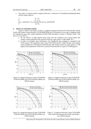
The simulations illustrated in Figure 11 show that 4-States TCM-QPSK with Viterbi soft decoder
outperforms 4-States TCM-QPSK with the Viterbi hard decoder, where a gain of 4 dB can be achieved by
using Viterbi soft decoder at BER= .
Figure 12 shows, at high signal-to-noise ratios, that the curve of log-map is the same as max-log-
map decoders but both outperform the Viterbi soft and map algorithms and the gain can be easily obtained
from the log-map or max-log-map which equal to 2 dB at BER compared to the Viterbi soft. The
BER performance is as follows: BER Log-Map = BER max-log-map < BER Vitrebi Soft < BER MAP.
Figure 12. Comparison between RSC TCM 8PSK with a MAP, Log-Map, and Max-log-map and Viterbi soft
decoders over AWGN channel.
7. CONCLUSION
In this paper, the simulation in MATLAB was used to evaluate the performance of Viterbi using
window system compared to the classical Viterbi. The simulation results over AWGN channel with rates
1/2, 1/3 and 2/3, have shown that at a BER of 10-6, the Viterbi decoder with window system outperforms the
classical Viterbi by 1 dB. Moreover, we propose the use of the Ungerbeock gray mapping to achieve more
performance with TCM encoder where the gain of 2.7dB was achieved compared to the TCM with the
Viterbi decoder by window system and the gain of 3.8dB is observed compared to the original TCM with the
classical Viterbi decoder.
From the above results, it can also be seen that with rate 2/3 the TCM with recursive systematic
convolutional (RSC) encoder with log-map or max-log-map decoders gives better results than Viterbi soft
with a gain of 2 dB at BER = 10-4 .
It is also clearly shown that Viterbi soft outperforms the MAP algorithm which is known as being
greedy in memory space and in the computing time which increases more if we increase the rate and the
number of memory. Consequently, the decoding operation becomes long. For this reason, they have
simplified MAP with others varying as log-MAP and max-log-MAP that are used on the new trend of
encoders like turbo-code where the researchers are placed a lot of hopes in this last technique (turbo codes)
because we approach the limit given by the second theorem of Shannon.
REFERENCES
[1] L.Conde Canancia, “Turbo-codes et modulation à grande efficacité spectrale,” these de doctorat de l‟université de
Bretagne Occidentale, France, Juin 2004.
[2] Ungerboeck, “Channel coding with multilevel/phase signals,” IEEE Transactions on Iinformation Theory, vol. IT-
28,N 1, Jan.1982,pp.55-67.
[3] Manish Kumar, Jyoti Saxena, Performance Comparison of Latency for RSC-RSC and RS-RSC Concatenated
Codes , Indonesian Journal of Electrical Engineering and Informatics (IJEEI), Vol. 1, No. 3, September 2013, pp.
78~83, ISSN: 2089-3272, DOI: 10.11591/ijeei.v1i3.77.
[4] Ilesanmi Banjo Oluwafemi, Hybrid Concatenated Coding Scheme for MIMO Systems, International Journal of
Electrical and Computer Engineering (IJECE), Vol. 5, No. 3, June 2015, pp. 464~476, ISSN: 2088-8708.
[5] Sameer A Dawood, F. Malek, MS Anuar, HA Rahim, Enhancement the Performance of OFDM based on
Multiwavelets Using Turbo Codes, TELKOMNIKA (Telecommunication Computing Electronics and Control), Vol.](https://image.slidesharecdn.com/v6628dec188aug8311iaespaperrevised2editern-201106062510/85/Improving-The-Performance-of-Viterbi-Decoder-using-Window-System-10-320.jpg)
![Int J Elec & Comp Eng ISSN: 2088-8708
Improving The Performance Of Viterbi Decoder using Window System (Rekkal Kahina)
621
13, No. 4, December 2015, pp. 1225~1232, ISSN: 1693-6930, accredited A by DIKTI, Decree No:
58/DIKTI/Kep/2013.
[6] A. Bassou and A. Djebbari, “Contribution to the Improvement of the Performance of Trellis-Coded Modulation,”
WSEAS Transactions on Communications, Vol. 6, No. 2, pp. 307-311, February 2006.
[7] Trio Adiono, Ahmad Zaky Ramdani, Rachmad Vidya Wicaksana Putra, “Reversed-Trellis Tail-Biting
Convolutional Code (RT-TBCC) Decoder Architecture Design for LTE”, International Journal of Electrical and
Computer Engineering (IJECE), Vol 8, No 1 February 2018.
[8] G.D.Jr.Forney, “The Viterbi Algorithme,, “ IEEE Proceedings, Mar. 1974.
[9] O. Pothier « codage de canal et turbo code cours 1 : introduction générale au codage de canal », Support de cours,
ENST Brest 2000. Source.
[10] J. Hagenauer and P. Hoeher, “A Viterbi Algorithm With Soft-Decision Outputs and Its Applications”, Proceedings
of GLOBECOM ‟89, Dallas, Texas, pp. 47.1.1-47.1.7, November 1989.
[11] W. Koch and A. Baier, “Optimum and sub-optimum detection of coded data disturbed by timevarying inter-symbol
interference,” Proceedings of IEEE Globecom, pp. 1679–1684, December 1990.
[12] J. A. Erfanian, S. Pasupathy and G. Gulak, “Reduced complexity symbol detectors with parallel structures for ISI
channels,” IEEE Trans. Communications, vol. 42, pp. 1661–1671, 1994.
[13] P. Robertson, E. Villebrun and P. Hoeher, “A comparison of optimal and sub-optimal MAP decoding algorithms
operating in the log domain”, Proc. Intern. Conf. Communications (ICC), pp. 1009–1013, June 1995.](https://image.slidesharecdn.com/v6628dec188aug8311iaespaperrevised2editern-201106062510/85/Improving-The-Performance-of-Viterbi-Decoder-using-Window-System-11-320.jpg)