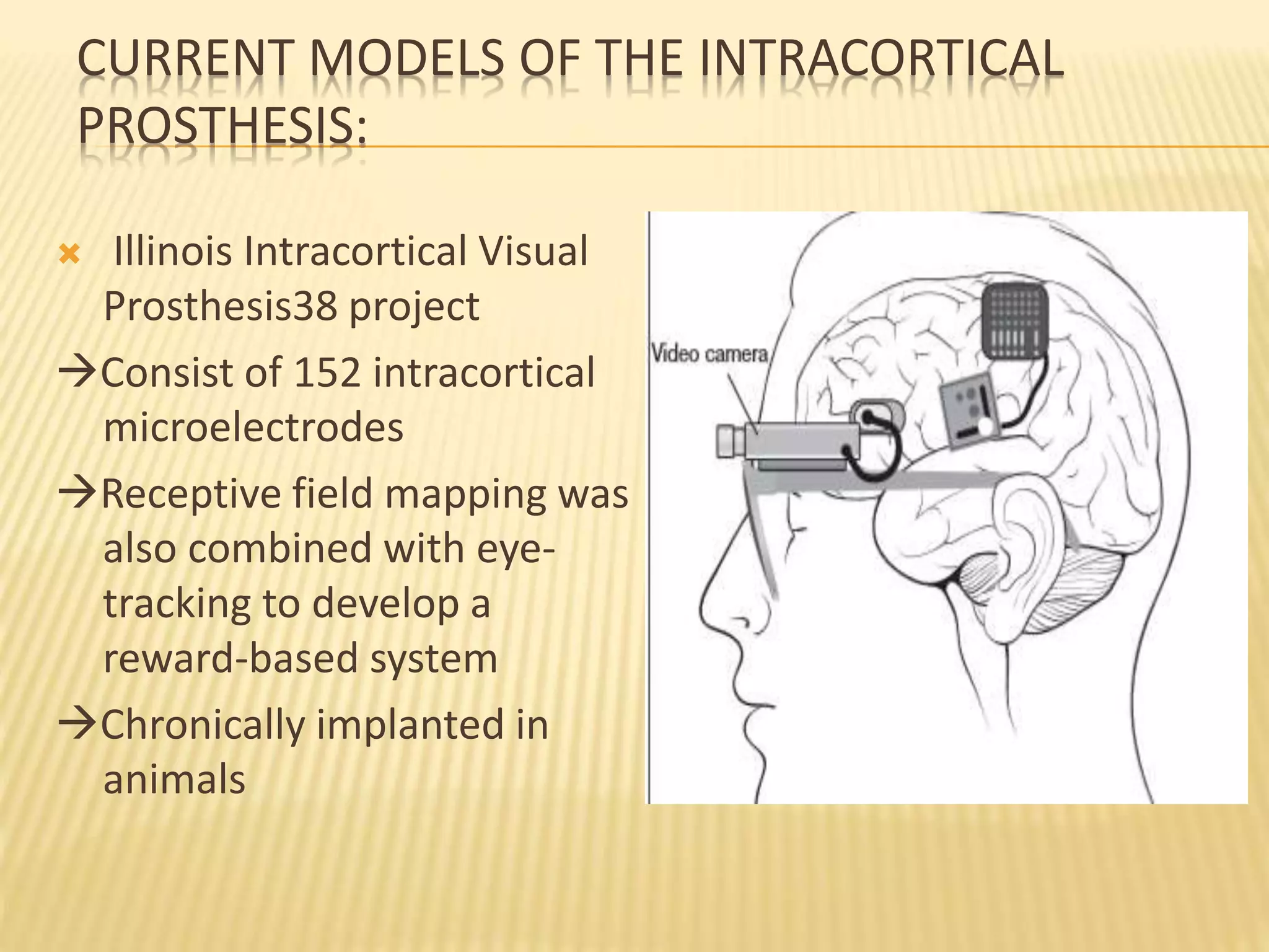
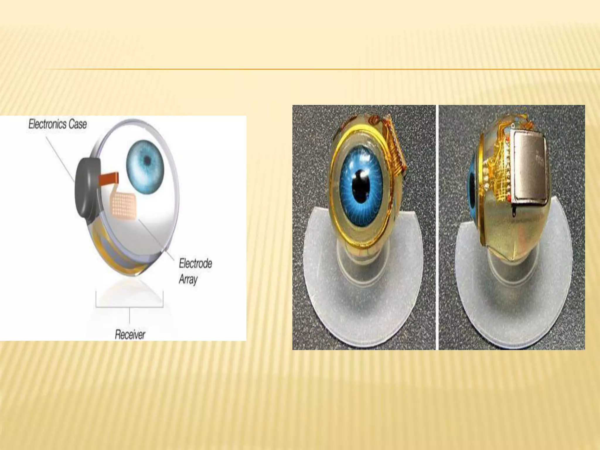
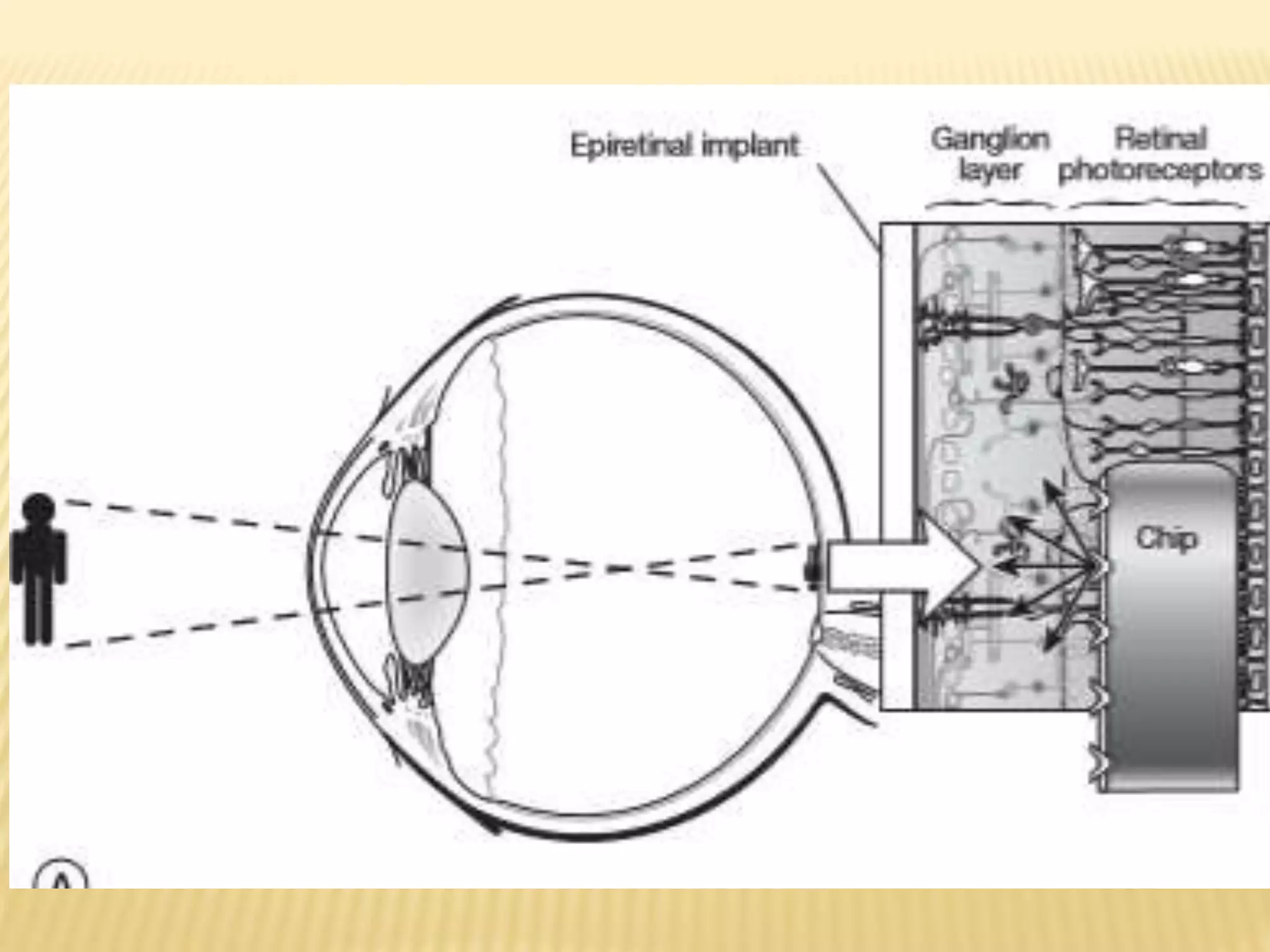
BY
DR ANJALI MAHESHWARI
VISUAL PROSTHESIS
INTRODUCTION
 Visual prostheses are based on neuronal electrical
stimulation at different locations along the visual pathway
(i.e., cortical, optic nerve, epiretinal, subretinal)
 Restores useful vision by converting visual information into
patterns of electrical stimulation that excite remaining
spared inner retinal neurons in diseases such as RP and AMD
 Basically replicated the natural vision of eye
 For vision to occur, 2 conditions need to be met :
1. An image must be formed on the retina
2. Resulting nerve impulses must be conducted to the visual
areas of the cerebral cortex for interpretation.
 Four processes focus light rays, so that they form a clear
image on the retina:
1. Refraction of light rays
2. Accommodation of the lens
3. Constriction of the pupil
4. Convergence of the eyes
VISUAL PATHWAY
 Normal physiologic vision is initiated when light passes
through the cornea and lens of the eye to the rods and
cones of the photoreceptor layer on the outer surface of the
retina initiating photochemical transduction.
HISTORY OF ARTIFICIAL VISION
 Concept of electronically stimulating the nervous system
to create artificial vision - first introduced in 1929 by
Foerster, a German neurosurgeon
 He observed that electrical stimulation of the visual
cortex caused his subject to detect a spot of light known
as phosphene.
 Pioneer establishing an electrical artificial vision system -
1960s by Giles Brindley.
 He implanted 80-electrode device on to the visual cortex of
a blind patient – showing electrical stimulation to restore
vision and the barriers to implementation of a suitable
device
 For artificial prosthesis to work it is essential to establish a
definition of useful vision that is based on the minimum
number of pixels required for human beings to accomplish
activities of daily living.
 Recent studies determind that 625 electrodes implanted in a
1-cm square area near the foveal representation in the visual
cortex could produce :
 Image with a visual acuity of approximately 20/30
 reading rates near 170 words/min with scrolled text
 100 words/min with fixed text
 Classification of visual prosthesis based on site of
implantation :
1. Cortical prosthesis
2. Optic nerve prosthesis
3. Retinal prosthesis
4. Suprachoroidal prosthesis
CORTICAL PROSTHESIS
 Cortical prosthesis has ability to return the sensation of
vision to individuals who had severed visual pathway
anterior to the visual cortex
 Dobelle’s 64-channel platinum electrode surface stimulation
prosthesis allowed blind patients to recognize 1.5-cm
characters at 1.5 m (approximately 20/1200 visual acuity).
DIFFICULTIES FACED
 Controlling the number of phosphenes induced by each
electrode
 Interactions between phosphenes
 Use of high currents and large electrodes that induced pain
from meningeal stimulation
 Occasional focal epileptic activity following electrical
stimulation
 Complaints of haloes around phosphenes
 Surface cortical implants were difficult to use because of the
location of visual cortex deep in calcarine fissure
 Intracortical devices :
 smaller electrodes closer to the target neurons
 requiring less current
 more localized stimulation.
ADVANTAGES OG INTRACORTICAL DEVICES
 Stimulus threshold is 10 to 100 times lower for intracortical
prostheses as compared to surface stimulation .
 Closer spacing of electrodes at 500 μm apart hence higher
resolution.
 predictable forms of elicited phosphenes
 absence of flicker phenomenon
 reduction in phosphene interactions
 increased number of electrodes
CURRENT MODELS OF THE INTRACORTICAL
PROSTHESIS:
 Illinois Intracortical Visual
Prosthesis38 project
Consist of 152 intracortical
microelectrodes
Receptive field mapping was
also combined with eye-
tracking to develop a
reward-based system
Chronically implanted in
animals
 Utah electrode array36
multiple silicon spikes
organized in a square grid
measuring 4.2 ×4.2 mm.
Platinum electrode at tip of
each spike.
 Pneumatic system - inserts
100 electrode devices into
cortex in about 200 ms -
minimal trauma during
insertion of this array.
Advantage: bypasses all
diseased visual pathway
neurons rostral to the primary
visual cortex.
LIMITATIONS OF CORTICAL PROSTHESIS
 Histological changes for chronically implanted prostheses
need to be further investigated.
 Tissue reaction in silicon-doped penetrating electrodes :
 None
 Thin capsule around each electrode track
 Gliosis
 Buildup of fibrotic tissue between the array and
meninges.
 Visual field organization is more complex at the level of the
primary cortex than at the retina or optic nerve and is not
easily reproducible
 High level of specialization of every area of cortex for various
parameters, including color, motion, and eye movement
 Surgical complications of this approach carry significant
morbidity and mortality for the patient.
OPTIC NERVE PROSTHESIS
 Veraart’s group – gave concept of a spiral nerve cuff
electrode
 Electrode cuff is surgically implanted circumferentially on the
external surface of the optic nerve.
 Does not penetrate the optic nerve sheath
 Relies on the principle of retinal mapping within the optic
nerve.
 Cuff electrode was
implanted intracranially.
 Cable passes through the
skull and courses below the
skin and along the outer
surface of the skull.
 Then passes down the neck
to exit the skin below the
clavicle
DIFFICULTIES
 Optic nerve a densely consolidated neural structure so
difficult to achieve focal stimulation of neurons and exact
retinal mapping of the optic nerve.
 Dense packing of neurons requires large number of
electrode contacts from the prosthesis in a small area,
increasing the risk of damage to the nerve.
 Surgical manipulation requires dissection of the dura,
causing harmful central nervous system effects like infection
and interruption of blood flow to the optic nerve.
 Limited to the treatment of outer retinal (photoreceptor)
degenerations
RETINAL PROSTHESIS
 Microelectronic retinal implant - for cases in which the
patient is affected by an outer retinopathy, as with RP or
AMD
 Potts and co-workers demonstrated electrically elicited
response (EER) via ocular stimulation using a contact lens as
a stimulating electrode
 Humayun et al. demonstrated - controlled electrical
stimulation of the retina creates visual sensations in blind
patients
TYPES OF RETINAL PROSTHESIS
 Epiretinal approach - device is
implanted into the vitreous cavity
and attached to the inner retinal
surface so the electrical
stimulation meets inner retina
first.
 Subretinal approach – device
implanted into potential space
between the neurosensory retina
and the retinal pigment
epithelium so electrical
stimulation meets outer retina
EPIRETINAL PROSTHESIS
 Humayun et al pioneered an intraocular retinal prosthesis
(IRP).
 IRP includes both:
External, wearable component
Implantable, intraocular component
 The external portion comprises:
 light-weight camera built into spectacles
 pocket batteries
 small pager-sized visual processing unit.
 Power and data are sent wirelessly from this external unit to
the internal portion of the prosthesis.
 The implanted portion consists of :
 Receiver/stimulating microelectronic chip
 Microelectrode array, currently including 16 platinum
electrodes trodes of 500 μm diameter
 The electrode array is affixed to the epiretinal surface by a
retinal tack.
 Till date model 1 device (Second Sight, LLC) has been
implanted in 3 patients.
each platinum electrode is labeled with a unique designation
for localization of percepts. This implant is located in the
macula. Soc- secondary coil , RF- radiofrequency antennae
 Model 2 device is under development - may incorporate
MEMS component so that the retina–implant interface is
more flexible frame for attachment.
ARGUS-II DEVICE
 The Argus II Retinal Prosthesis System (“Argus II”) is the
world’s first approved device intended to restore some
functional vision for people suffering from blindness.
 Transmits images from a small, eye-glass- mounted
camera wirelessly to a microelectrode array
implanted on a patient’s damaged retina.
 Argus II is approved for patients with outer retinal
degenerative disease such as retinitis pigmentosa
(RP) and choroideremia.
 Surgical considerations:
Bare light perception
 No optic nerve problems
 Evidence of intact inner layer retinal function must be
confirmed before implantation
 Adverse events included :
 hypotony
 conjunctival dehiscence
 conjunctival erosion
 presumed endophthalmitis
 adverse events are quite low with good surgical technique
THE ARGUS® II RETINAL PROSTHESIS SYSTEM
WORKING OF ARGUS-II DEVICE
 The patient wears glasses with an attached video camera
that captures images of the surrounding area.
 These images become an electrical signal which is
processed by the video processing unit. The signal is then
wirelessly delivered to the eye stimulating the retina.
 This electrical stimulation of the retina is recognized by the
brain as spots of light
ADVANTAGES
 It identify the location or movement ofobjects and
people.
 Recognize large letters,words, or sentences.
 Helps in other activities of daily life,such as detecting
street curbs and walking on a sidewalk without stepping
off.
SURGICAL TECHNIQUE
 There are two stages to the surgery :
 fastens a silicone band, which has a receiver affixed to it,
around the eye.
procedure is similar to attaching a scleral buckle, which is
performed to treat retinal detachments.
 A cable connected to a microelectrode array hangs loose
from the receiver as the surgeon prepares for the next stage.
 performing a viterectomy- removes the vitreous of the
eye while refilling it with balanced salt solution, which
preserves the shape of the eye.
 slides the microelectrode array into the eye
 sutures the eye closed around the array’s cable and then
enters the eye through another port.
 place the microelectrode array over the macula, or retinal
center, and presses a single tack into the eye wall to place
the Argus II on the delicate retinal tissue
 After about one month, when the eye has healed:
Patient puts on the glasses and turns on the camera and
computer processor.
The camera captures a digital image and sends it to the
computer processor pack that the patient wears on a belt,
which converts the image into electrical nerve conduction
signals.
These signals are wirelessly sent to the receiver fastened
to the silicone band around the eyeball.
 The receiver sends the signals through the cable to the
microelectrode array tacked onto the retina, which
stimulates the retina and produces the pixelized vision.
 Rehabilitiation process is then started which may take upto 6
months.
CURRENT STATUS OF ARGUS II
 Argus II has been implanted in more than 190 patients
worldwide.
 Results to date indicate that the device is reasonably reliable
and stable option for patients with advanced RP.
 Similar technology:
 Iris-II epiretinal implant (Pixium Vision) is in clinical trials
in Europe.
 The device is designed for patients with RP, has 150
electrodes
ADVANTAGES
 Epiretinal placement allows for the vitreous to act as a sink
for heat dissipation from the microelectronic device
 Minimal number of microelectronics are incorporated into
theimplantable portion of the device
 Wearable portion of electronics allows for easy upgrades
without requiring subsequent surgery
 Electronics allow the user and the doctor full control over
every electrode parameter and digital signal processing
involved in imaging objects, allowing the implant to be
customized for each patient
DISADVANTAGES
 Requirement of techniques that will provide prolonged
adhesion of the device to the inner retina
 Further distance of the epiretinal device to the target
bipolar cells than the subretinal device requires increased
current.
SUBRETINAL PROSTHESIS
 The subretinal approach to the retinal prosthesis involves
implanting a microphotodiode array (MPDA) between the
bipolar cell layer and retinal pigment epithelium
 Surgically either via
 intraocular approach through a retinotomy site (ab
interno) or
 transscleral approach (ab externo).
ALPHA-IMS
 Developed by Retina Implant in Germany
 3×3-mm microchip that is implanted in a subfoveal position.
 Chip contains 1,500 light-sensitive photodiodes that are
joined to microelectrodes.
 Does not use an external camera , the photodiodes are cou-
pled to an external power module that is implanted under
the skin behind the ear and amplifies the signals generated
by the photodiode array.
 approved in Europe for patients with RP
 Benefit: patient does not need to use head scanning to
locate objects and normal eye movements can be used.
 Implantation procedure :
 Complex
 Help is also needed from a cochlear implant surgeon to
place the power supply under the skin behind the ear
 Most difficult part is positioning the chip underneath the
retina
 Similar development:
 Stanford researchers have developed a wireless
photovoltaic subretinal prosthesis.
 Recipients will wear goggles that capture images and
project them into the eye and onto an implanted
photodiode array
 Light is then converted into pulsed current, which
stimulates inner retinal neurons.
 The prosthesis known as Prima, is now being prepared
for clinical trials.
LIMITATIONS
 Illumination levels required in order to achieve adequate
electrical current generation are not realistically attainable.
 Will require active power supplementation from an external
source in order to achieve threshold current levels.
 Advantages :
 closer proximity to the next surviving neuron in the visual
pathway (i.e., bipolar cell) and therefore less current
requirement
 lack of a mechanical means of fixation.
 Disadvantages :
 Limited space to place electronics as well as the close
proximity of the retina to the electronics which would
increase the likelihood of thermal injury to the neurons.
 If the subretinal implant has electronics outside the eye
(ab externo approach), then implant have a cable piercing
the sclera; the tethering effect on the cable and the
electrodes will need to be solved.
 Long cable in the Subretinal space will require a
transchoroidal incision, resulting in a greater likelihood of
massive subretinal hemorrhage as well as possible retinal
detachment, whether total or localized
SUPRACHOROIDAL PROSTHESIS
 Placed between the choroid and the sclera.
 Variation - suprachoroidal-transretinal device is implanted
between the layers of the sclera rather than in the
suprachoroidal space.
 Bionic Vision Australia.
24-channel prototype suprachoroidal prosthesis that
comprises an intraocular electrode array in a 19×8-mm
silicone base.
 It has 33 platinum stimulating electrodes and 2 return
electrodes
 outer ring of electrodes are ganged together to enable
hexagonal stimulation, meaning that 20 electrodes can be
stimulated individually
 Intended for patients with outer retinal degenerative disease
such as RP or choroideremia.
 Candidates for current trials - remaining visual acuity of light
perception or less in both eyes.
 Suprachoroidal location advantages:
 surgery is less challenging
 Does not breach the retinal tissue thus negating the need
for a vitrectomy or incisions into the retina.
excellent safety profile
 Current status:
 In 2012, BVA researchers implanted the device in 3
patients with end-stage RP.
 This first-in-human trial showed - anatomical position for
the array is a viable, minimally invasive, and relatively
straightforward location for an electrode array
CURRENT AVAILABILITY OF BIONICS IN INDIA
 Bionic eye or retinal implant has been co-invented by an
Indian origin Scientist, Dr Rajat N Agrawal, an
ophthalmologist and retina specialist/surgeon, University of
Southern California, US.
 He is presently working in collaboration with All India
Institute of Medical Sciences and several IITs to indigenously
develop a cheaper variant of the eye implant so that people
in India can afford it.
 The indigenously developed implant is expected to bring
down the cost to Rs 5 lakh from its present cost of Rs 45
lakh.
 Indian bionics market is still lagging behind as compared to
markets of other countries.
REFERENCES
 Stephen J Ryan’s Retina
 https://www.aao.org/eyenet/article/bionic-
vision
THANK YOU

Visual prosthesis

  • 1.
  • 2.
    INTRODUCTION  Visual prosthesesare based on neuronal electrical stimulation at different locations along the visual pathway (i.e., cortical, optic nerve, epiretinal, subretinal)  Restores useful vision by converting visual information into patterns of electrical stimulation that excite remaining spared inner retinal neurons in diseases such as RP and AMD  Basically replicated the natural vision of eye
  • 3.
     For visionto occur, 2 conditions need to be met : 1. An image must be formed on the retina 2. Resulting nerve impulses must be conducted to the visual areas of the cerebral cortex for interpretation.  Four processes focus light rays, so that they form a clear image on the retina: 1. Refraction of light rays 2. Accommodation of the lens 3. Constriction of the pupil 4. Convergence of the eyes
  • 4.
    VISUAL PATHWAY  Normalphysiologic vision is initiated when light passes through the cornea and lens of the eye to the rods and cones of the photoreceptor layer on the outer surface of the retina initiating photochemical transduction.
  • 5.
    HISTORY OF ARTIFICIALVISION  Concept of electronically stimulating the nervous system to create artificial vision - first introduced in 1929 by Foerster, a German neurosurgeon  He observed that electrical stimulation of the visual cortex caused his subject to detect a spot of light known as phosphene.
  • 6.
     Pioneer establishingan electrical artificial vision system - 1960s by Giles Brindley.  He implanted 80-electrode device on to the visual cortex of a blind patient – showing electrical stimulation to restore vision and the barriers to implementation of a suitable device
  • 7.
     For artificialprosthesis to work it is essential to establish a definition of useful vision that is based on the minimum number of pixels required for human beings to accomplish activities of daily living.  Recent studies determind that 625 electrodes implanted in a 1-cm square area near the foveal representation in the visual cortex could produce :  Image with a visual acuity of approximately 20/30  reading rates near 170 words/min with scrolled text  100 words/min with fixed text
  • 8.
     Classification ofvisual prosthesis based on site of implantation : 1. Cortical prosthesis 2. Optic nerve prosthesis 3. Retinal prosthesis 4. Suprachoroidal prosthesis
  • 9.
    CORTICAL PROSTHESIS  Corticalprosthesis has ability to return the sensation of vision to individuals who had severed visual pathway anterior to the visual cortex  Dobelle’s 64-channel platinum electrode surface stimulation prosthesis allowed blind patients to recognize 1.5-cm characters at 1.5 m (approximately 20/1200 visual acuity).
  • 10.
    DIFFICULTIES FACED  Controllingthe number of phosphenes induced by each electrode  Interactions between phosphenes  Use of high currents and large electrodes that induced pain from meningeal stimulation  Occasional focal epileptic activity following electrical stimulation  Complaints of haloes around phosphenes
  • 11.
     Surface corticalimplants were difficult to use because of the location of visual cortex deep in calcarine fissure  Intracortical devices :  smaller electrodes closer to the target neurons  requiring less current  more localized stimulation.
  • 12.
    ADVANTAGES OG INTRACORTICALDEVICES  Stimulus threshold is 10 to 100 times lower for intracortical prostheses as compared to surface stimulation .  Closer spacing of electrodes at 500 μm apart hence higher resolution.  predictable forms of elicited phosphenes  absence of flicker phenomenon  reduction in phosphene interactions  increased number of electrodes
  • 13.
    CURRENT MODELS OFTHE INTRACORTICAL PROSTHESIS:  Illinois Intracortical Visual Prosthesis38 project Consist of 152 intracortical microelectrodes Receptive field mapping was also combined with eye- tracking to develop a reward-based system Chronically implanted in animals
  • 14.
     Utah electrodearray36 multiple silicon spikes organized in a square grid measuring 4.2 ×4.2 mm. Platinum electrode at tip of each spike.  Pneumatic system - inserts 100 electrode devices into cortex in about 200 ms - minimal trauma during insertion of this array. Advantage: bypasses all diseased visual pathway neurons rostral to the primary visual cortex.
  • 15.
    LIMITATIONS OF CORTICALPROSTHESIS  Histological changes for chronically implanted prostheses need to be further investigated.  Tissue reaction in silicon-doped penetrating electrodes :  None  Thin capsule around each electrode track  Gliosis  Buildup of fibrotic tissue between the array and meninges.
  • 16.
     Visual fieldorganization is more complex at the level of the primary cortex than at the retina or optic nerve and is not easily reproducible  High level of specialization of every area of cortex for various parameters, including color, motion, and eye movement  Surgical complications of this approach carry significant morbidity and mortality for the patient.
  • 17.
    OPTIC NERVE PROSTHESIS Veraart’s group – gave concept of a spiral nerve cuff electrode  Electrode cuff is surgically implanted circumferentially on the external surface of the optic nerve.  Does not penetrate the optic nerve sheath  Relies on the principle of retinal mapping within the optic nerve.
  • 18.
     Cuff electrodewas implanted intracranially.  Cable passes through the skull and courses below the skin and along the outer surface of the skull.  Then passes down the neck to exit the skin below the clavicle
  • 19.
    DIFFICULTIES  Optic nervea densely consolidated neural structure so difficult to achieve focal stimulation of neurons and exact retinal mapping of the optic nerve.  Dense packing of neurons requires large number of electrode contacts from the prosthesis in a small area, increasing the risk of damage to the nerve.
  • 20.
     Surgical manipulationrequires dissection of the dura, causing harmful central nervous system effects like infection and interruption of blood flow to the optic nerve.  Limited to the treatment of outer retinal (photoreceptor) degenerations
  • 21.
    RETINAL PROSTHESIS  Microelectronicretinal implant - for cases in which the patient is affected by an outer retinopathy, as with RP or AMD  Potts and co-workers demonstrated electrically elicited response (EER) via ocular stimulation using a contact lens as a stimulating electrode  Humayun et al. demonstrated - controlled electrical stimulation of the retina creates visual sensations in blind patients
  • 22.
    TYPES OF RETINALPROSTHESIS  Epiretinal approach - device is implanted into the vitreous cavity and attached to the inner retinal surface so the electrical stimulation meets inner retina first.  Subretinal approach – device implanted into potential space between the neurosensory retina and the retinal pigment epithelium so electrical stimulation meets outer retina
  • 23.
    EPIRETINAL PROSTHESIS  Humayunet al pioneered an intraocular retinal prosthesis (IRP).  IRP includes both: External, wearable component Implantable, intraocular component
  • 24.
     The externalportion comprises:  light-weight camera built into spectacles  pocket batteries  small pager-sized visual processing unit.  Power and data are sent wirelessly from this external unit to the internal portion of the prosthesis.
  • 25.
     The implantedportion consists of :  Receiver/stimulating microelectronic chip  Microelectrode array, currently including 16 platinum electrodes trodes of 500 μm diameter  The electrode array is affixed to the epiretinal surface by a retinal tack.  Till date model 1 device (Second Sight, LLC) has been implanted in 3 patients.
  • 26.
    each platinum electrodeis labeled with a unique designation for localization of percepts. This implant is located in the macula. Soc- secondary coil , RF- radiofrequency antennae
  • 27.
     Model 2device is under development - may incorporate MEMS component so that the retina–implant interface is more flexible frame for attachment.
  • 28.
    ARGUS-II DEVICE  TheArgus II Retinal Prosthesis System (“Argus II”) is the world’s first approved device intended to restore some functional vision for people suffering from blindness.  Transmits images from a small, eye-glass- mounted camera wirelessly to a microelectrode array implanted on a patient’s damaged retina.  Argus II is approved for patients with outer retinal degenerative disease such as retinitis pigmentosa (RP) and choroideremia.
  • 29.
     Surgical considerations: Barelight perception  No optic nerve problems  Evidence of intact inner layer retinal function must be confirmed before implantation
  • 30.
     Adverse eventsincluded :  hypotony  conjunctival dehiscence  conjunctival erosion  presumed endophthalmitis  adverse events are quite low with good surgical technique
  • 32.
    THE ARGUS® IIRETINAL PROSTHESIS SYSTEM
  • 33.
    WORKING OF ARGUS-IIDEVICE  The patient wears glasses with an attached video camera that captures images of the surrounding area.  These images become an electrical signal which is processed by the video processing unit. The signal is then wirelessly delivered to the eye stimulating the retina.  This electrical stimulation of the retina is recognized by the brain as spots of light
  • 35.
    ADVANTAGES  It identifythe location or movement ofobjects and people.  Recognize large letters,words, or sentences.  Helps in other activities of daily life,such as detecting street curbs and walking on a sidewalk without stepping off.
  • 36.
    SURGICAL TECHNIQUE  Thereare two stages to the surgery :  fastens a silicone band, which has a receiver affixed to it, around the eye. procedure is similar to attaching a scleral buckle, which is performed to treat retinal detachments.  A cable connected to a microelectrode array hangs loose from the receiver as the surgeon prepares for the next stage.  performing a viterectomy- removes the vitreous of the eye while refilling it with balanced salt solution, which preserves the shape of the eye.
  • 37.
     slides themicroelectrode array into the eye  sutures the eye closed around the array’s cable and then enters the eye through another port.  place the microelectrode array over the macula, or retinal center, and presses a single tack into the eye wall to place the Argus II on the delicate retinal tissue
  • 38.
     After aboutone month, when the eye has healed: Patient puts on the glasses and turns on the camera and computer processor. The camera captures a digital image and sends it to the computer processor pack that the patient wears on a belt, which converts the image into electrical nerve conduction signals. These signals are wirelessly sent to the receiver fastened to the silicone band around the eyeball.  The receiver sends the signals through the cable to the microelectrode array tacked onto the retina, which stimulates the retina and produces the pixelized vision.
  • 39.
     Rehabilitiation processis then started which may take upto 6 months.
  • 40.
    CURRENT STATUS OFARGUS II  Argus II has been implanted in more than 190 patients worldwide.  Results to date indicate that the device is reasonably reliable and stable option for patients with advanced RP.  Similar technology:  Iris-II epiretinal implant (Pixium Vision) is in clinical trials in Europe.  The device is designed for patients with RP, has 150 electrodes
  • 41.
    ADVANTAGES  Epiretinal placementallows for the vitreous to act as a sink for heat dissipation from the microelectronic device  Minimal number of microelectronics are incorporated into theimplantable portion of the device  Wearable portion of electronics allows for easy upgrades without requiring subsequent surgery  Electronics allow the user and the doctor full control over every electrode parameter and digital signal processing involved in imaging objects, allowing the implant to be customized for each patient
  • 42.
    DISADVANTAGES  Requirement oftechniques that will provide prolonged adhesion of the device to the inner retina  Further distance of the epiretinal device to the target bipolar cells than the subretinal device requires increased current.
  • 43.
    SUBRETINAL PROSTHESIS  Thesubretinal approach to the retinal prosthesis involves implanting a microphotodiode array (MPDA) between the bipolar cell layer and retinal pigment epithelium  Surgically either via  intraocular approach through a retinotomy site (ab interno) or  transscleral approach (ab externo).
  • 45.
    ALPHA-IMS  Developed byRetina Implant in Germany  3×3-mm microchip that is implanted in a subfoveal position.  Chip contains 1,500 light-sensitive photodiodes that are joined to microelectrodes.  Does not use an external camera , the photodiodes are cou- pled to an external power module that is implanted under the skin behind the ear and amplifies the signals generated by the photodiode array.  approved in Europe for patients with RP
  • 46.
     Benefit: patientdoes not need to use head scanning to locate objects and normal eye movements can be used.  Implantation procedure :  Complex  Help is also needed from a cochlear implant surgeon to place the power supply under the skin behind the ear  Most difficult part is positioning the chip underneath the retina
  • 47.
     Similar development: Stanford researchers have developed a wireless photovoltaic subretinal prosthesis.  Recipients will wear goggles that capture images and project them into the eye and onto an implanted photodiode array  Light is then converted into pulsed current, which stimulates inner retinal neurons.  The prosthesis known as Prima, is now being prepared for clinical trials.
  • 48.
    LIMITATIONS  Illumination levelsrequired in order to achieve adequate electrical current generation are not realistically attainable.  Will require active power supplementation from an external source in order to achieve threshold current levels.
  • 49.
     Advantages : closer proximity to the next surviving neuron in the visual pathway (i.e., bipolar cell) and therefore less current requirement  lack of a mechanical means of fixation.
  • 50.
     Disadvantages : Limited space to place electronics as well as the close proximity of the retina to the electronics which would increase the likelihood of thermal injury to the neurons.  If the subretinal implant has electronics outside the eye (ab externo approach), then implant have a cable piercing the sclera; the tethering effect on the cable and the electrodes will need to be solved.  Long cable in the Subretinal space will require a transchoroidal incision, resulting in a greater likelihood of massive subretinal hemorrhage as well as possible retinal detachment, whether total or localized
  • 51.
    SUPRACHOROIDAL PROSTHESIS  Placedbetween the choroid and the sclera.  Variation - suprachoroidal-transretinal device is implanted between the layers of the sclera rather than in the suprachoroidal space.  Bionic Vision Australia. 24-channel prototype suprachoroidal prosthesis that comprises an intraocular electrode array in a 19×8-mm silicone base.  It has 33 platinum stimulating electrodes and 2 return electrodes  outer ring of electrodes are ganged together to enable hexagonal stimulation, meaning that 20 electrodes can be stimulated individually
  • 52.
     Intended forpatients with outer retinal degenerative disease such as RP or choroideremia.  Candidates for current trials - remaining visual acuity of light perception or less in both eyes.  Suprachoroidal location advantages:  surgery is less challenging  Does not breach the retinal tissue thus negating the need for a vitrectomy or incisions into the retina. excellent safety profile
  • 53.
     Current status: In 2012, BVA researchers implanted the device in 3 patients with end-stage RP.  This first-in-human trial showed - anatomical position for the array is a viable, minimally invasive, and relatively straightforward location for an electrode array
  • 55.
    CURRENT AVAILABILITY OFBIONICS IN INDIA  Bionic eye or retinal implant has been co-invented by an Indian origin Scientist, Dr Rajat N Agrawal, an ophthalmologist and retina specialist/surgeon, University of Southern California, US.  He is presently working in collaboration with All India Institute of Medical Sciences and several IITs to indigenously develop a cheaper variant of the eye implant so that people in India can afford it.  The indigenously developed implant is expected to bring down the cost to Rs 5 lakh from its present cost of Rs 45 lakh.  Indian bionics market is still lagging behind as compared to markets of other countries.
  • 56.
    REFERENCES  Stephen JRyan’s Retina  https://www.aao.org/eyenet/article/bionic- vision
  • 57.