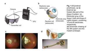
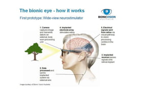
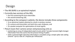
Retinal prostheses are implantable devices designed to restore vision in patients with retinal diseases that have destroyed photoreceptors. The document describes three types of retinal prostheses - epiretinal, subretinal, and suprachoroidal - based on their implantation site. It provides details on the design, surgical procedure, and clinical outcomes of some specific retinal prosthesis devices, including the Bionic Vision Australia suprachoroidal implant and the Retina Implant Alpha-IMS subretinal implant. Complications of retinal prostheses are also discussed.

![Introduction
• Retinal prostheses are implantable devices designed to supplant
phototransduction within the eyes of individuals with significant retinal diseases
such as retinitis pigmentosa.
• In the normal eye, photoreceptors located within the outer layers of the retina
contain light-sensitive pigment that trigger the phototransduction cascade to
generate neuronal signals in the presence of light stimuli.
• These signals are passed to and processed by a complex network of neurons within the middle
layers of the retina before reaching the retinal ganglion cells (RGC) RNFL Visual cortex.
• In congenital retinal dystrophies such as retinitis pigmentosa,
• the outer layers of the retina where photoreceptors reside are gradually lost, thereby causing
progressive visual loss.
• However, inner retinal layers including RGCs are partially spared.[1]
• In theory then, restoration of vision may be achieved by creating devices, retinal prostheses,
that receive and process incoming light and then transmit the information in the form of
electrical impulses to the remaining inner retinal layers for visual function.](https://image.slidesharecdn.com/retinalprosthesis-200201162939/85/Retinal-prosthesis-2-320.jpg)


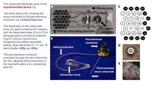
![Results
• Three subjects with light perception visual acuity due to outer retinal degenerative
diseases (2 with rod-cone dystrophy, 1 with syndromic retinitis pigmentosa) were
implanted with suprachoroidal retinal prosthesis devices and percutaneous
connectors.
• Post-surgical hemorrhage in the subretinal and suprachoroidal spaces was noted in all
subjects, but in each case spontaneously resolved without further complications.
• Device stability and integrity was measured regularly using fundus photography,
infrared imaging, OCT, and impedance studies.
• Imaging showed no movements of the device, but distance from the device to the RPE
markedly increased over the course of the year in two subjects [roughly 600 µ to 900 µ ]
• Impedance studies showed significantly decreased micro-electrode impedance in one subject
over time which was thought to be due to changes in the electrode-tissue interface.
• All 3 subjects scored significantly better with the device on than with it off in the
• Visual acuity was estimated to be logMAR 2.62 (20/8397) on average with the device on.
• With the device off, the same subject was unable to see any Landolt-C optotypes.](https://image.slidesharecdn.com/retinalprosthesis-200201162939/85/Retinal-prosthesis-22-320.jpg)

![Fundus photo of Retina Implant Alpha-
IMS device
The Alpha-IMS is a subretinal, micro-photodiode array retinal
prosthesis developed by Retina Implant AG in Reutlingen,
Germany and approved in Europe in 2013.
It is designed to be implanted in the layer of degenerated
photoreceptor cells in patients with degenerative outer retinal
disease.
Consequently, electrical impulses from the device stimulate
bipolar cells in the middle retinal layers which carry the signals
to RGCs.
An earlier version of the device with a retroauricular transdermal
cable connected the device to an external battery and was
implanted in 11 blind volunteers beginning in 2005. After positive
visual function outcomes, a wireless version was developed
which is currently undergoing single and multi-center clinical trials
in Europe.[18]](https://image.slidesharecdn.com/retinalprosthesis-200201162939/85/Retinal-prosthesis-24-320.jpg)

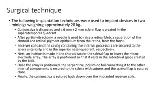
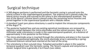
![Surgical technique
• Surgical implantation consists of extra- and intra-ocular procedures which may be performed
consecutively over 6-8 hours.
• The extraocular procedure begins with a 4 cm arcuate, retroauricular incision and a secondary,
horizontal incision of about the same size crossing the first. A raspatory is used to dissect down
to the bone to expose an approximately 2 cm by 2 cm square of retroauricular bone upon and
then a standard otologic drill is used to make a 3-4 mm deep implant bed for the ceramic casing
containing electronics. Another incision is made near the lateral orbital rim over the margo
orbitalis and the zygomatic-frontalis suture is exposed by elevating the periosteum.
• Intraorbital periosteum is also elevated to allow for an L-shaped canal to be drilled. A complete
peritomy is performed at the limbus, and a tunnel is dissected from the subconjunctival space to
the orbital rim incision.
• A silicone tube is inserted to keep it patent. Next, a 15 cm long, raspatory is used to tunnel
beneath the periosteum of the temporal bone to connect the orbital rim incision with the
retroauricular site.
• Then, a custom, hollow trocar is inserted anteriorly beneath the temporal periosteum and
extended through to the retroauricular incision site. The power cable and subretinal implant
components, protected by a silicone tube, are pulled from the retroauricular site to the orbital
rim using the trocar and then inserted through the tunnel to the subconjunctival space. Prior to
the intraocular procedure, electrical testing of the implant is performed. The extraocular surgery
takes approximately 60-80 minutes.[20][21]](https://image.slidesharecdn.com/retinalprosthesis-200201162939/85/Retinal-prosthesis-26-320.jpg)
![• To begin the intraocular procedure, a standard pars-plana victretomy is
performed and then a 1 by 4 mm scleral flap made 9 mm posterior to the
limbus in the supero-temporal quadrant. The retina is elevated by injecting
balanced saline solution or Healon. Then, a guiding tool is inserted through
the sclera and choroid to a subretinal position between the choroid and the
retina.
• Correct insertion and positioning of the guiding tool may be aided by
calculating the optimal angle and distance of insertion and making a line
between an insertion point and reference point marked by a corneal marker.
• Insertion depth may be calculated and tracked by calibration lines on the
guidance tool. The polyimide foil is then introduced along the path of the
guiding foil to the subretinal space.
• The outside end of the foil is connected to a sealed ceramic connector piece
which is sutured onto the sclera. Finally a macular hole is created by
separating the pigment epithelium layer from the neuroretina and the array is
placed according to planned positioning as seen on fundus images prior to
surgery.[20][22]](https://image.slidesharecdn.com/retinalprosthesis-200201162939/85/Retinal-prosthesis-27-320.jpg)
![• Alpha-IMS devices have been implanted in at least 29 participants within single and multi-center
modules as a part of an ongoing clinical trial by Zrenner and colleagues.[18] Those receiving implants
had either no light perception or light perception without projection due to degenerative outer
retinal diseases (25 had retinitis pigmentosa, 4 had cone-rod dystrophy) prior to implantation.
• Of the 29 participants, at least two serious adverse events have been reported – one increase of
intraocular pressure up to 46 mmHg and the other a retinal detachment immediately after
explantation of the device.[23] Both were treated and managed without long-term sequelae.
• Notably, after implantation 4 of the 29 subjects could not perceive any light while the device was
turned on. Though the cause was unclear, the Stingl et al. attributed this result to either failure of
the device in vivo or to sequelae of the implantation surgery such as inflammation of the optic
nerve or retina.[18]
• The following results are a summary of visual function test performances of 29 implanted subjects
described by Stingl and colleagues in their 2015 clinical trial interim report.
• According to the interim report, subjects with the Alpha-IMS turned on were significantly more
likely to correctly perceive and localize flashes of light on a screen 60 cm away than with the device
turned off, but there was no significant difference in ability to recognize the direction of movement
of the flashes. These tests were performed according to the Basic Assessment of Light and Motion
which has been described previously.
• With the device on, subjects were also significantly more likely to correctly tell the orientation of a
grating than with it off, but no significant difference was seen when testing acuity with Landolt C-
rings. Of the 4 subjects who passed the Landolt C-ring test, one passed with a visual acuity of
20/546.](https://image.slidesharecdn.com/retinalprosthesis-200201162939/85/Retinal-prosthesis-28-320.jpg)


![• The EPIRET3 system was designed by the EPI-RET Project group in
Germany to be a wirelessly controlled, epiretinal device.
• Electrical impulses are transferred to the retina by 25, 100 micrometer diameter
electrodes arrayed in a hexagonal pattern coated in a thin film of iridium oxide
and affixed to the end of a via a 40 mm long, 3 mm wide polyimide foil micro-
cable which connects the electrodes to a receiver module implanted within the
lens capsule.
• The receiver module consists of a receiver coil that wirelessly obtains transmitted
data, a receiver chip that processes that data, and a stimulation chip that
generates and sends impulse activation patterns to the micro-electrode array. The
entire implant is coated with parylene C for biocompatibility.[29] The internal coil
receives temporospatial data and power wirelessly from an external coil and
transmitter unit attached to glasses in front of the eye. Data and power originate
from a portable computer system worn or carried by the user.](https://image.slidesharecdn.com/retinalprosthesis-200201162939/85/Retinal-prosthesis-40-320.jpg)
![Results
• Successful experimental implantation and explantation of the EPIRET3
system in 6 subjects was reported in 2009 by Roessler and colleagues.
• Per ethics guidelines, the devices remained in the eyes for only 28 days before
explantation.
• Subjects all carried diagnoses of retinitis pigmentosa confirmed by ERG and had
visual acuities ranging from no light perception (1/6 patients) to light perception
(4/6) to hand movements (1/6).
• No severe adverse events were reported in any of the subjects. However, one
patient developed culture-negative hypopyon on post-implantation day 3 which
was treated and cleared by day 5.
• During explantation, a different subject developed a macular hole which
was filled with silicone oil. Although minor gliosis was visible on
angiography near tack sites, visual acuity was stable at long-term follow-
up for all patients.[28][30]](https://image.slidesharecdn.com/retinalprosthesis-200201162939/85/Retinal-prosthesis-42-320.jpg)

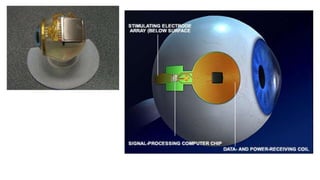
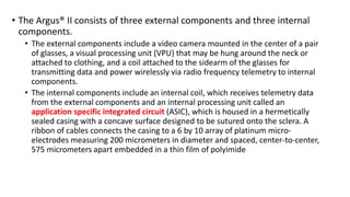
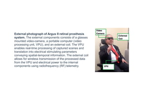
![Design
• The Argus® II is a second-generation epiretinal, micro-electrode array retinal
prosthesis developed and sold by Second Sight Medical Products.
• It recently was approved for marketing in both Europe (2011) and the United
States (2013), being the first device to gain that distinction.
• Its design differs from the first generation model, the Argus I, in the number and
spacing of microelectrodes on the array (6x10 instead of 4x4), the placement of
internal processing components (sutured onto the sclera instead of subcutaneous
placement inside the temporal recess), and the placement of the external
transmission coil (built into the sidearm of the glasses instead of held magnetically by
the internal components over the temporal bone).[8]](https://image.slidesharecdn.com/retinalprosthesis-200201162939/85/Retinal-prosthesis-45-320.jpg)


![Artificial retina [shweta]](https://cdn.slidesharecdn.com/ss_thumbnails/artificialretinashweta-161013192718-thumbnail.jpg?width=640&height=640&fit=bounds)


