Downloaded 356 times


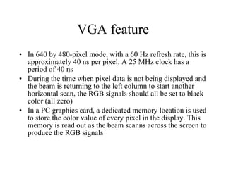


![Cam : OmniVision OV6620 Features : 101,376 pixel, CIF/QCIF format Array Size 356x 292 pixels - 8/16 bit video data : CCIR601, CCIR656, ZV port - Data format YCrCb 4:2:2, GRB 4:2:2, RGB I2C interface for reconfiguration We only focus & use : - default configuration : 352x288 - Pclk : Pixel clock - Href : Horizontal window reference - Vsync : Vertical Sync - Y[7:0] : 8 Bit luminance data bus](https://image.slidesharecdn.com/vga-display-101226143714-phpapp02/85/VGA-VHDL-RTL-design-tutorial-18-320.jpg)


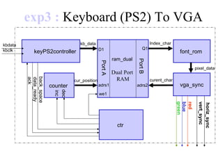

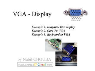
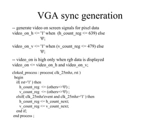
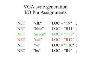
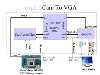
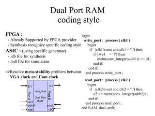
The document discusses three examples of connecting devices to a VGA display: 1) Drawing a diagonal line, 2) Connecting a camera to output video, 3) Connecting a keyboard to display text. It provides details on VGA signal generation, dual-port RAM for buffering between asynchronous clock domains, and example code for interfacing a PS/2 keyboard to generate on-screen text.