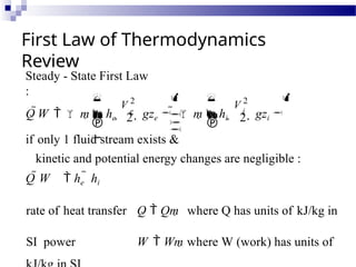
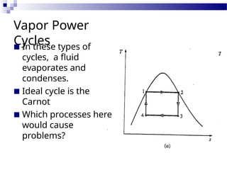
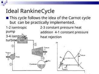
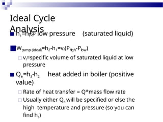
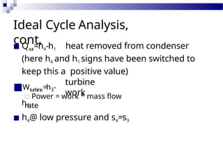
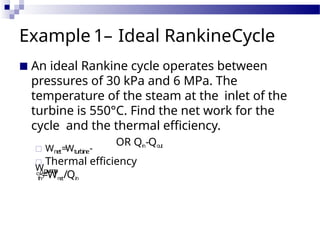
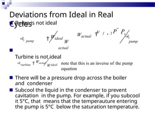
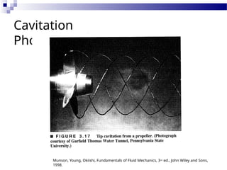
Rankine
Cycle
First Law of Thermodynamics
Review
2 2
Steady - State First Law
:
V 2
V 2
if only 1 fluid stream exists &
kinetic and potential energy changes are negligible :
Q W  he  hi
rate of heat transfer Q  Qm where Q has units of kJ/kg in
SI power W  Wm where W (work) has units of


 



  


Q W   m  he  e
 gze
   m  hi  i
 gzi

Vapor Power
Cycles
■ In these types of
cycles, a fluid
evaporates and
condenses.
■ Ideal cycle is the
Carnot
■ Which processes here
would cause
problems?
Ideal RankineCycle
■ This cycle follows the idea of the Carnot cycle
but can be practically implemented.
1-2 isentropic
pump
3-4 isentropic
turbine
2-3 constant pressure heat
addition 4-1 constant pressure
heat rejection
Ideal Cycle
Analysis
■ h1=hf@ low pressure (saturated liquid)
■Wp
ump (ideal)=h2-h1=vf(Phigh-Plow)
□ vf=specific volume of saturated liquid at low
pressure
■ Qin=h3-h2 heat added in boiler (positive
value)
□ Rate of heat transfer = Q*mass flow rate
□ Usually either Qin will be specified or else the
high temperature and pressure (so you can
find h3)
Ideal Cycle Analysis,
cont.
■ Qout=h4-h1 heat removed from condenser
(here h4 and h1 signs have been switched to
keep this a positive value)
■Wturbine=h3-
h4
turbine
work
□ Power = work * mass flow
rate
■ h4@ low pressure and s4=s3
Example 1– Ideal RankineCycle
■ An ideal Rankine cycle operates between
pressures of 30 kPa and 6 MPa. The
temperature of the steam at the inlet of the
turbine is 550°C. Find the net work for the
cycle and the thermal efficiency.
□ Wnet=Wturbine-
Wpump
OR Qi
n-Qo
u
t
□ Thermal efficiency

th=Wn
et/Qin
Deviations from Ideal in Real
Cycles
■
■ There will be a pressure drop across the boiler
and condenser
Subcool the liquid in the condenser to prevent
cavitation in the pump. For example, if you subcool
it 5°C, that means that the temperauture entering
the pump is 5°C below the saturation temperature.
■
■ Pump is not ideal
 pump  Wideal
W
actual
Turbine is not ideal
v  P  P 
Wactual  f 2 1

pump
note that this is an inverse of the pump
equation
ideal
turbine  Wactual
W
Cavitation
Photos
Munson, Young, Okiishi, Fundamentals of Fluid Mechanics, 3rd ed., John Wiley and Sons,
1998.
Example
2
■ Repeat the last problem but with an
isentropic pump efficiency of 75% and
turbine efficiency of 85%.
T-s
Diagrams
■ Draw a T-s diagram for an ideal Rankine
Cycle. Now show how that diagram will
change if you keep the pressures the same
but increase the superheating. What
happens to
□ Pump work input?
□ Turbine work output?
□ Heat rejected?
□ Moisture content at turbine exit?
T-s
Diagrams
■ Draw a T-s diagram for an ideal Rankine
Cycle. Now show how that diagram will
change if you bix the turbine inlet
temperature and condenser pressure but
increase the boiler pressure. What happens
to
□ Pump work input?
□ Heat rejected?
□ Moisture content at exit of turbine?
To increase system
efficiency
■ Lower condenser pressure
□ Must have at least 10°C T between condenser
and cooling water or air temperature for
effective heat transfer
□ Watch quality at exit to prevent turbine
problems (shouldn’t go less than about 88%)
■ Superheat the steam more
□ Tm
a
x ~ 620° due to metallurgical considerations
■ Increase boiler pressure (with same Tm
a
x)
□ Pm
a
x ~ 30 MPa
□ Watch quality at exit
Reheat Cycle
■ Allows us to increase boiler pressure
without problems of low quality at
turbine exit
Regeneratio
n
■ Preheats steam entering boiler
using a feedwater heater, improving
efficiency
□ Also deaerates the fluid and reduces large
volume flow rates at turbine exit.
A more complicated
cycle…
CombinedCycle

rankine cycle-Class notes for thermodynamics

  • 1.
  • 2.
    First Law ofThermodynamics Review 2 2 Steady - State First Law : V 2 V 2 if only 1 fluid stream exists & kinetic and potential energy changes are negligible : Q W  he  hi rate of heat transfer Q  Qm where Q has units of kJ/kg in SI power W  Wm where W (work) has units of             Q W   m  he  e  gze    m  hi  i  gzi 
  • 3.
    Vapor Power Cycles ■ Inthese types of cycles, a fluid evaporates and condenses. ■ Ideal cycle is the Carnot ■ Which processes here would cause problems?
  • 4.
    Ideal RankineCycle ■ Thiscycle follows the idea of the Carnot cycle but can be practically implemented. 1-2 isentropic pump 3-4 isentropic turbine 2-3 constant pressure heat addition 4-1 constant pressure heat rejection
  • 5.
    Ideal Cycle Analysis ■ h1=hf@low pressure (saturated liquid) ■Wp ump (ideal)=h2-h1=vf(Phigh-Plow) □ vf=specific volume of saturated liquid at low pressure ■ Qin=h3-h2 heat added in boiler (positive value) □ Rate of heat transfer = Q*mass flow rate □ Usually either Qin will be specified or else the high temperature and pressure (so you can find h3)
  • 6.
    Ideal Cycle Analysis, cont. ■Qout=h4-h1 heat removed from condenser (here h4 and h1 signs have been switched to keep this a positive value) ■Wturbine=h3- h4 turbine work □ Power = work * mass flow rate ■ h4@ low pressure and s4=s3
  • 7.
    Example 1– IdealRankineCycle ■ An ideal Rankine cycle operates between pressures of 30 kPa and 6 MPa. The temperature of the steam at the inlet of the turbine is 550°C. Find the net work for the cycle and the thermal efficiency. □ Wnet=Wturbine- Wpump OR Qi n-Qo u t □ Thermal efficiency  th=Wn et/Qin
  • 8.
    Deviations from Idealin Real Cycles ■ ■ There will be a pressure drop across the boiler and condenser Subcool the liquid in the condenser to prevent cavitation in the pump. For example, if you subcool it 5°C, that means that the temperauture entering the pump is 5°C below the saturation temperature. ■ ■ Pump is not ideal  pump  Wideal W actual Turbine is not ideal v  P  P  Wactual  f 2 1  pump note that this is an inverse of the pump equation ideal turbine  Wactual W
  • 9.
    Cavitation Photos Munson, Young, Okiishi,Fundamentals of Fluid Mechanics, 3rd ed., John Wiley and Sons, 1998.
  • 10.
    Example 2 ■ Repeat thelast problem but with an isentropic pump efficiency of 75% and turbine efficiency of 85%.
  • 11.
    T-s Diagrams ■ Draw aT-s diagram for an ideal Rankine Cycle. Now show how that diagram will change if you keep the pressures the same but increase the superheating. What happens to □ Pump work input? □ Turbine work output? □ Heat rejected? □ Moisture content at turbine exit?
  • 12.
    T-s Diagrams ■ Draw aT-s diagram for an ideal Rankine Cycle. Now show how that diagram will change if you bix the turbine inlet temperature and condenser pressure but increase the boiler pressure. What happens to □ Pump work input? □ Heat rejected? □ Moisture content at exit of turbine?
  • 13.
    To increase system efficiency ■Lower condenser pressure □ Must have at least 10°C T between condenser and cooling water or air temperature for effective heat transfer □ Watch quality at exit to prevent turbine problems (shouldn’t go less than about 88%) ■ Superheat the steam more □ Tm a x ~ 620° due to metallurgical considerations ■ Increase boiler pressure (with same Tm a x) □ Pm a x ~ 30 MPa □ Watch quality at exit
  • 14.
    Reheat Cycle ■ Allowsus to increase boiler pressure without problems of low quality at turbine exit
  • 15.
    Regeneratio n ■ Preheats steamentering boiler using a feedwater heater, improving efficiency □ Also deaerates the fluid and reduces large volume flow rates at turbine exit.
  • 16.
  • 17.