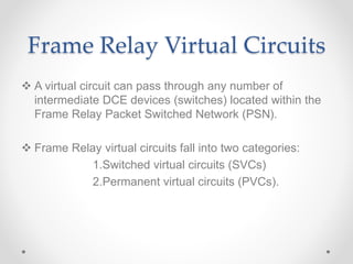
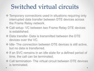
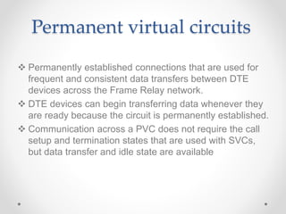
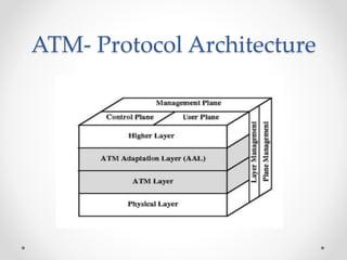
FRAME RELAY
 Frame Relay - high-performance WAN protocol
 Operates at the physical and data link layers
of the OSI reference model.
 Frame Relay originally was designed for use across
Integrated Services Digital Network (ISDN) interfaces
 Based on packet-switched technology
 Frame relay provides connection-oriented data link layer
communication.
FRAME RELAY NETWORK
 This service is implemented by using a Frame Relay
virtual circuit, which is a logical connection created
between two data terminal equipment (DTE) devices
across a Frame Relay packet-switched network (PSN).
 Virtual circuits provide a bidirectional communication
path from one DTE device to another and are uniquely
identified by a Data-Link Connection Identifier (DLCI).
 A number of virtual circuits can be multiplexed into a
single physical circuit for transmission across the
network.
 Frame Relay uses virtual circuits to carry packets from
one DTE to another.
FR FRAME
 Flags indicate the beginning and end of the frame.
 Address area, which is 2 bytes in length, is
comprised of 10 bits representing the actual circuit
identifier and 6 bits of fields related to congestion
management.
 This identifier commonly is referred to as the data-
link connection identifier (DLCI).
Frame Relay Virtual Circuits
 A virtual circuit can pass through any number of
intermediate DCE devices (switches) located within the
Frame Relay Packet Switched Network (PSN).
 Frame Relay virtual circuits fall into two categories:
1.Switched virtual circuits (SVCs)
2.Permanent virtual circuits (PVCs).
Switched virtual circuits
 Temporary connections used in situations requiring only
interrupted data transfer between DTE devices across
the Frame Relay network.
 Call setup- VC between two Frame Relay DTE devices
is established.
 Data transfer- Data is transmitted between the DTE
devices over the VC.
 Idle- The connection between DTE devices is still active,
but no data is transferred.
 If an SVC remains in an idle state for a defined period of
time, the call can be terminated.
 Call termination- The virtual circuit between DTE devices
is terminated.
Permanent virtual circuits
 Permanently established connections that are used for
frequent and consistent data transfers between DTE
devices across the Frame Relay network.
 DTE devices can begin transferring data whenever they
are ready because the circuit is permanently established.
 Communication across a PVC does not require the call
setup and termination states that are used with SVCs,
but data transfer and idle state are available
ATM- Protocol Architecture
 ATM has its own reference model different from OSI or
TCP/IP model.
 If ATM is viewed as a Network Layer protocol, then the
corresponding Transport Layer protocol is the ATM
Adaptation Layer (AAL).
Physical Layer
 Responsible for transmission of ATM cells as a bit-
stream across physical medium.
 Divided into Physical Medium Dependent (PMD) sub-
layer and Transmission Convergence (TC) sub-layer.
 Data rates specified include 155 and 622 Mbps with
other data rates possible
PMD sub-layer
 Interfaces the actual cable.
 provides width of bit and line coding depending (NRZ,
RZ, Manchester etc.) on particular physical medium.
TC sub-layer
 It consists of transmission functions independent of
physical medium.
 It converts the ATM cell (from ATM layer) into normal bit
string (like TTL).
 TC sub-layer also converts the ATM cell into frame
ATM Adaptation Layer
 Supports transfer protocols not based on ATM.
 It maps higher layer information into ATM cells to be
transported over an ATM network.
 collects information from ATM cells for delivery to higher
layers (e.g. a IP packet can be mapped to ATM cells).
ATM Planes
There are 3 planes in the protocol architecture:
 User plane - for user traffic including flow and error
control
 Control plane - for connection control
 Management plane - manages the system as a whole
and coordinates the planes and layers.
Advantages of Virtual Path
 Simplified network architecture
 Increased network performance and reliability
 Reduced processing and short connection setup time
 Enhanced network services
THANK YOU

Frame_Relay_High_speed_communication.pptx

  • 1.
    FRAME RELAY  FrameRelay - high-performance WAN protocol  Operates at the physical and data link layers of the OSI reference model.  Frame Relay originally was designed for use across Integrated Services Digital Network (ISDN) interfaces  Based on packet-switched technology  Frame relay provides connection-oriented data link layer communication.
  • 2.
  • 3.
     This serviceis implemented by using a Frame Relay virtual circuit, which is a logical connection created between two data terminal equipment (DTE) devices across a Frame Relay packet-switched network (PSN).  Virtual circuits provide a bidirectional communication path from one DTE device to another and are uniquely identified by a Data-Link Connection Identifier (DLCI).  A number of virtual circuits can be multiplexed into a single physical circuit for transmission across the network.  Frame Relay uses virtual circuits to carry packets from one DTE to another.
  • 4.
    FR FRAME  Flagsindicate the beginning and end of the frame.  Address area, which is 2 bytes in length, is comprised of 10 bits representing the actual circuit identifier and 6 bits of fields related to congestion management.  This identifier commonly is referred to as the data- link connection identifier (DLCI).
  • 5.
    Frame Relay VirtualCircuits  A virtual circuit can pass through any number of intermediate DCE devices (switches) located within the Frame Relay Packet Switched Network (PSN).  Frame Relay virtual circuits fall into two categories: 1.Switched virtual circuits (SVCs) 2.Permanent virtual circuits (PVCs).
  • 6.
    Switched virtual circuits Temporary connections used in situations requiring only interrupted data transfer between DTE devices across the Frame Relay network.  Call setup- VC between two Frame Relay DTE devices is established.  Data transfer- Data is transmitted between the DTE devices over the VC.  Idle- The connection between DTE devices is still active, but no data is transferred.  If an SVC remains in an idle state for a defined period of time, the call can be terminated.  Call termination- The virtual circuit between DTE devices is terminated.
  • 7.
    Permanent virtual circuits Permanently established connections that are used for frequent and consistent data transfers between DTE devices across the Frame Relay network.  DTE devices can begin transferring data whenever they are ready because the circuit is permanently established.  Communication across a PVC does not require the call setup and termination states that are used with SVCs, but data transfer and idle state are available
  • 8.
  • 9.
     ATM hasits own reference model different from OSI or TCP/IP model.  If ATM is viewed as a Network Layer protocol, then the corresponding Transport Layer protocol is the ATM Adaptation Layer (AAL).
  • 10.
    Physical Layer  Responsiblefor transmission of ATM cells as a bit- stream across physical medium.  Divided into Physical Medium Dependent (PMD) sub- layer and Transmission Convergence (TC) sub-layer.  Data rates specified include 155 and 622 Mbps with other data rates possible
  • 11.
    PMD sub-layer  Interfacesthe actual cable.  provides width of bit and line coding depending (NRZ, RZ, Manchester etc.) on particular physical medium. TC sub-layer  It consists of transmission functions independent of physical medium.  It converts the ATM cell (from ATM layer) into normal bit string (like TTL).  TC sub-layer also converts the ATM cell into frame
  • 12.
    ATM Adaptation Layer Supports transfer protocols not based on ATM.  It maps higher layer information into ATM cells to be transported over an ATM network.  collects information from ATM cells for delivery to higher layers (e.g. a IP packet can be mapped to ATM cells).
  • 13.
    ATM Planes There are3 planes in the protocol architecture:  User plane - for user traffic including flow and error control  Control plane - for connection control  Management plane - manages the system as a whole and coordinates the planes and layers.
  • 14.
    Advantages of VirtualPath  Simplified network architecture  Increased network performance and reliability  Reduced processing and short connection setup time  Enhanced network services
  • 15.