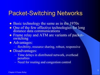
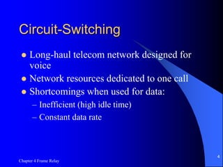
Chapter 4 Frame Relay
1
Chapter 4
Frame Relay
Chapter 4 Frame Relay
2
Introduction
 Packet-Switching Networks
– Switching Technique
– Routing
– X.25
 Frame Relay Networks
– Architecture
– User Data Transfer
– Call Control
Chapter 4 Frame Relay
3
Packet-Switching Networks
 Basic technology the same as in the 1970s
 One of the few effective technologies for long
distance data communications
 Frame relay and ATM are variants of packet-
switching
 Advantages:
– flexibility, resource sharing, robust, responsive
 Disadvantages:
– Time delays in distributed network, overhead
penalties
– Need for routing and congestion control
Chapter 4 Frame Relay
4
Circuit-Switching
 Long-haul telecom network designed for
voice
 Network resources dedicated to one call
 Shortcomings when used for data:
– Inefficient (high idle time)
– Constant data rate
Chapter 4 Frame Relay
5
Packet-Switching
 Data transmitted in short blocks, or packets
 Packet length < 1000 octets
 Each packet contains user data plus control
info (routing)
 Store and forward
Chapter 4 Frame Relay
6
Figure 4.1 The Use of Packets
Chapter 4 Frame Relay
7
Figure 4.2 Packet
Switching:
Datagram
Approach
Chapter 4 Frame Relay
8
Advantages over Circuit-Switching
 Greater line efficiency (many packets can
go over shared link)
 Data rate conversions
 Non-blocking under heavy traffic (but
increased delays)
Chapter 4 Frame Relay
9
Disadvantages relative to Circuit-
Switching
 Packets incur additional delay with every
node they pass through
 Jitter: variation in packet delay
 Data overhead in every packet for routing
information, etc
 Processing overhead for every packet at
every node traversed
Chapter 4 Frame Relay
10
Figure 4.3 Simple Switching
Network
Chapter 4 Frame Relay
11
Switching Technique
 Large messages broken up into smaller packets
 Datagram
– Each packet sent independently of the others
– No call setup
– More reliable (can route around failed nodes or
congestion)
 Virtual circuit
– Fixed route established before any packets sent
– No need for routing decision for each packet at each
node
Chapter 4 Frame Relay
12
Figure 4.4 Packet
Switching: Virtual-
Circuit Approach
Chapter 4 Frame Relay
13
Routing
 Adaptive routing
 Node/trunk failure
 Congestion
Chapter 4 Frame Relay
14
X.25
 3 levels
 Physical level (X.21)
 Link level (LAPB, a subset of HDLC)
 Packet level (provides virtual circuit
service)
Chapter 4 Frame Relay
15
Figure 4.5 The Use of Virtual
Circuits
Chapter 4 Frame Relay
16
Figure 4.6 User Data and X.25
Protocol Control Information
Chapter 4 Frame Relay
17
Frame Relay Networks
 Designed to eliminate much of the overhead in
X.25
 Call control signaling on separate logical
connection from user data
 Multiplexing/switching of logical connections at
layer 2 (not layer 3)
 No hop-by-hop flow control and error control
 Throughput an order of magnitude higher than
X.25
Chapter 4 Frame Relay
18
Figure 4.7 Comparison of X.25
and Frame Relay Protocol Stacks
Chapter 4 Frame Relay
19
Figure 4.8 Virtual Circuits and
Frame Relay Virtual Connections
Chapter 4 Frame Relay
20
Frame Relay Architecture
 X.25 has 3 layers: physical, link, network
 Frame Relay has 2 layers: physical and
data link (or LAPF)
 LAPF core: minimal data link control
– Preservation of order for frames
– Small probability of frame loss
 LAPF control: additional data link or
network layer end-to-end functions
Chapter 4 Frame Relay
21
LAPF Core
 Frame delimiting, alignment and
transparency
 Frame multiplexing/demultiplexing
 Inspection of frame for length constraints
 Detection of transmission errors
 Congestion control
Chapter 4 Frame Relay
22
Figure 4.9 LAPF-core
Formats
Chapter 4 Frame Relay
23
User Data Transfer
 No control field, which is normally used
for:
– Identify frame type (data or control)
– Sequence numbers
 Implication:
– Connection setup/teardown carried on
separate channel
– Cannot do flow and error control
Chapter 4 Frame Relay
24
Frame Relay Call Control
 Frame Relay Call Control
 Data transfer involves:
– Establish logical connection and DLCI
– Exchange data frames
– Release logical connection
Chapter 4 Frame Relay
25
Frame Relay Call Control
4 message types needed, on the separate
connection dedicated to call control
(DLCI=0)
 SETUP
 CONNECT
 RELEASE
 RELEASE COMPLETE

Chapter04.pptAdvance concept of networking

  • 1.
    Chapter 4 FrameRelay 1 Chapter 4 Frame Relay
  • 2.
    Chapter 4 FrameRelay 2 Introduction  Packet-Switching Networks – Switching Technique – Routing – X.25  Frame Relay Networks – Architecture – User Data Transfer – Call Control
  • 3.
    Chapter 4 FrameRelay 3 Packet-Switching Networks  Basic technology the same as in the 1970s  One of the few effective technologies for long distance data communications  Frame relay and ATM are variants of packet- switching  Advantages: – flexibility, resource sharing, robust, responsive  Disadvantages: – Time delays in distributed network, overhead penalties – Need for routing and congestion control
  • 4.
    Chapter 4 FrameRelay 4 Circuit-Switching  Long-haul telecom network designed for voice  Network resources dedicated to one call  Shortcomings when used for data: – Inefficient (high idle time) – Constant data rate
  • 5.
    Chapter 4 FrameRelay 5 Packet-Switching  Data transmitted in short blocks, or packets  Packet length < 1000 octets  Each packet contains user data plus control info (routing)  Store and forward
  • 6.
    Chapter 4 FrameRelay 6 Figure 4.1 The Use of Packets
  • 7.
    Chapter 4 FrameRelay 7 Figure 4.2 Packet Switching: Datagram Approach
  • 8.
    Chapter 4 FrameRelay 8 Advantages over Circuit-Switching  Greater line efficiency (many packets can go over shared link)  Data rate conversions  Non-blocking under heavy traffic (but increased delays)
  • 9.
    Chapter 4 FrameRelay 9 Disadvantages relative to Circuit- Switching  Packets incur additional delay with every node they pass through  Jitter: variation in packet delay  Data overhead in every packet for routing information, etc  Processing overhead for every packet at every node traversed
  • 10.
    Chapter 4 FrameRelay 10 Figure 4.3 Simple Switching Network
  • 11.
    Chapter 4 FrameRelay 11 Switching Technique  Large messages broken up into smaller packets  Datagram – Each packet sent independently of the others – No call setup – More reliable (can route around failed nodes or congestion)  Virtual circuit – Fixed route established before any packets sent – No need for routing decision for each packet at each node
  • 12.
    Chapter 4 FrameRelay 12 Figure 4.4 Packet Switching: Virtual- Circuit Approach
  • 13.
    Chapter 4 FrameRelay 13 Routing  Adaptive routing  Node/trunk failure  Congestion
  • 14.
    Chapter 4 FrameRelay 14 X.25  3 levels  Physical level (X.21)  Link level (LAPB, a subset of HDLC)  Packet level (provides virtual circuit service)
  • 15.
    Chapter 4 FrameRelay 15 Figure 4.5 The Use of Virtual Circuits
  • 16.
    Chapter 4 FrameRelay 16 Figure 4.6 User Data and X.25 Protocol Control Information
  • 17.
    Chapter 4 FrameRelay 17 Frame Relay Networks  Designed to eliminate much of the overhead in X.25  Call control signaling on separate logical connection from user data  Multiplexing/switching of logical connections at layer 2 (not layer 3)  No hop-by-hop flow control and error control  Throughput an order of magnitude higher than X.25
  • 18.
    Chapter 4 FrameRelay 18 Figure 4.7 Comparison of X.25 and Frame Relay Protocol Stacks
  • 19.
    Chapter 4 FrameRelay 19 Figure 4.8 Virtual Circuits and Frame Relay Virtual Connections
  • 20.
    Chapter 4 FrameRelay 20 Frame Relay Architecture  X.25 has 3 layers: physical, link, network  Frame Relay has 2 layers: physical and data link (or LAPF)  LAPF core: minimal data link control – Preservation of order for frames – Small probability of frame loss  LAPF control: additional data link or network layer end-to-end functions
  • 21.
    Chapter 4 FrameRelay 21 LAPF Core  Frame delimiting, alignment and transparency  Frame multiplexing/demultiplexing  Inspection of frame for length constraints  Detection of transmission errors  Congestion control
  • 22.
    Chapter 4 FrameRelay 22 Figure 4.9 LAPF-core Formats
  • 23.
    Chapter 4 FrameRelay 23 User Data Transfer  No control field, which is normally used for: – Identify frame type (data or control) – Sequence numbers  Implication: – Connection setup/teardown carried on separate channel – Cannot do flow and error control
  • 24.
    Chapter 4 FrameRelay 24 Frame Relay Call Control  Frame Relay Call Control  Data transfer involves: – Establish logical connection and DLCI – Exchange data frames – Release logical connection
  • 25.
    Chapter 4 FrameRelay 25 Frame Relay Call Control 4 message types needed, on the separate connection dedicated to call control (DLCI=0)  SETUP  CONNECT  RELEASE  RELEASE COMPLETE