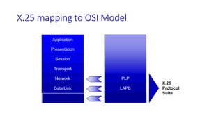
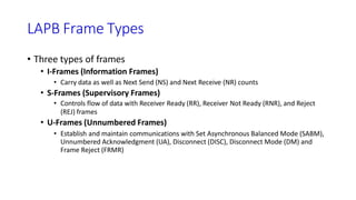
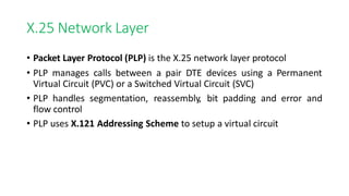
SlideShare a Scribd company logo
1
X.25
History and Overview
• Most common forms of virtual circuit packet switching are X.25 and
Frame Relay
• X.25 (ITU-it) is protocol standard for WAN communications
• It defines how connections between user devices and network
devices are established and maintained.
• X.25 is designed to operate effectively regardless of the type of
systems connected to the network.
• It is typically used in the packet-switched networks (PSNs) of
common carriers, such as the telephone companies
• Subscribers are charged based on their use of the network.
2
X.25
• The development of the X.25 standard was initiated by the common
carriers in the 1970s.
• At that time, there was a need for WAN protocols capable of
providing connectivity across public data networks (PDNs)
• X.25 is now administered as an international standard by the ITU-T.
X.25 Devices
• Data Terminal Equipment (DTE): end systems that communicate across the
X.25 network.
• Terminals, personal computers, and network hosts
• Located on premises of subscriber
• Data Circuit-terminating Equipment (DCE):that provide the interface
between DTE devices and a PSE,
• Modems and packet switches
• Usually located at carrier facility
• Packet Switching Exchange (PSE): transfer data from one DTE device to
another through the X.25 PSN
• Switches that make up the carrier network
Sample X.25 Network
X.25
WAN
Personal Computer
DTE
Terminal
DTE
Server
DTE
Modem
DCE
Modem
DCE
Modem
DCE
PSE
PSE
PSE
PSE
Packet Assembler/Disassembler (PAD)
• Acts as intermediary device between DTE and DCE
• Performs three functions
• Buffering to store data until a device is ready to process it
• Packet Assembly
• Packet Disassembly
PAD in Action
Terminal
DTE
Modem
DCE
PAD
Buffer
Data
Assembly/
Disassembly
Data
X.25 Packet
PSE
PSE
• The PAD buffers data sent to or from the DTE
device.
• It also assembles outgoing data into packets
and forwards them to the DCE device. (This
includes adding an X.25 header.)
• Finally, the PAD disassembles incoming packets
before forwarding the data to the DTE. (This
includes removing the X.25 header.)
Two types of X.25 virtual circuits exist
• Switched virtual circuits (SVCs) are temporary connections used for
irregular data transfers.
• They require that two DTE devices establish, maintain, and terminate a
session each time the devices need to communicate.
• Permanent virtual circuits (PVCs) are permanently established
connections used for frequent and consistent data transfers.
• PVCs do not require that sessions be established and terminated.
• Therefore, DTEs can begin transferring data whenever necessary because the
session is always active
9
X.25 mapping to OSI Model
Application
Presentation
Session
Transport
Network
Data Link
Physical
Other Services
PLP
LAPB
x.21 bis, EIA/TIA-232, EIA/TIA-449,
EIA-530, G.703
X.25
Protocol
Suite
Relationship between level of X.25
11
X.25 Physical Layer
• Several well-known standards are used for X.25 networks
• X.21bis – supports up to 2 Mbps
• 15-pin connector
• RS-232 (EIA/TIA-232) – supports up to 19.2 Kbps
• 25-pin connector
• RS-449 (EIA/TIA-449) – supports up to 64 Kbps
• 37-pin connector
• V.35 – supports up to 2 Mbps
• 34-pin connector
• Uses serial communications in either asynchronous or synchronous
modes
X.25 Data Link Layer
• Link Access Procedure, Balanced (LAPB) is the protocol used for this layer
• LAPB is a version of HDLC (High-Level Data Link Control protocol)
• HDLC in Asynchronous Balanced Mode (ABM)
• DTE and DCE are peers and can both perform all functions
• LAPB manages communication and packet framing between DTE and DCE devices
• Makes sure that frames are delivered in sequence and error-free
• Uses sliding window of 8 or 128 frames
LAPB Frame Types
• Three types of frames
• I-Frames (Information Frames)
• Carry data as well as Next Send (NS) and Next Receive (NR) counts
• S-Frames (Supervisory Frames)
• Controls flow of data with Receiver Ready (RR), Receiver Not Ready (RNR), and Reject
(REJ) frames
• U-Frames (Unnumbered Frames)
• Establish and maintain communications with Set Asynchronous Balanced Mode (SABM),
Unnumbered Acknowledgment (UA), Disconnect (DISC), Disconnect Mode (DM) and
Frame Reject (FRMR)
LAPB Frame Format
Flag Address Control Data FCS Flag
Flag: (8 bits) Indicates start and end of frame (01111110)
Address: (8 bits) DTE address is maintained in higher layer so this field is
used to identify command and responses between DTE and DCE. A value of
0x01 indicates a command from DTE and responses from DCE while a value
of 0x03 indicates commands from DCE and responses from DTE.
Control: (8 bits) Contains sequence numbers, commands and responses for
controlling data flow
Data: (varies is size) Contains upper layer data
FCS: (16 bits) Frame Check Sequence used to determine if an error has
occurred in transmission (variation of Cyclic Redundancy Check)
X.25 Network Layer
• Packet Layer Protocol (PLP) is the X.25 network layer protocol
• PLP manages calls between a pair DTE devices using a Permanent
Virtual Circuit (PVC) or a Switched Virtual Circuit (SVC)
• PLP handles segmentation, reassembly, bit padding and error and
flow control
• PLP uses X.121 Addressing Scheme to setup a virtual circuit
PLP Operates in Five Modes
• Call Setup
• Used to setup virtual circuit for SVC
• Data Transfer
• Used for transferring data with both SVC and PVC
• Idle
• Used when SVC call has been established but no data is currently being transferred
• Call Clearing
• Used to end communication between DTEs for a SVC
• Restarting
• Used to synchronize DTE and DCE for all virtual circuits that exist between them
PLP Frame Format
GFI LCI PTI User Data
• General Format Indicator: (4 bits) Identifies packet parameters, such as whether the
packet carries user data or control information, what kind of windowing is being used,
and whether delivery confirmation is required
• Bit 1 – 0=User Data, 1=Data for PAD
• Bit 2 – 0=Local Ack, 1=Remote Ack
• Bits 3 & 4 – 00=Reserved, 01=Window Size 8, 10=Window Size 128, 11=Extended
Format
• Logical Channel Identifier: (12 bits) Identifies the virtual circuit (1-4095) across the
local DTE to DCE interface. This field consists of a 4-bit Logical Channel Group
Number (LCGN) and an 8-bit Logical Channel Number (LCN)
• Packet Type Identifier: (8 bits) Identifies one of 17 different packet types
• User Data: (varies is size but typically 128 bits) Contain encapsulated user data for
data packets or additional control information for other packets
X.25 Call Setup
DTE to DCE
Interface
DCE to DTE
Interface
Call
Setup
Phase
Call Request
Call Connected
Incoming Call
Call Accepted
Data
Transfer
Phase
Data Packet
Incoming Data
Incoming Data
Data Packet
Call
Clearing
Phase
Clear Request
Clear Confirm
Clear Indication
Clear Response
18
Drawbacks of X.25
• X.25 has a low 64-kbps data rateBy the 1990s, there was a need
for higher data-rate WANs.
• X.25 has extensive flow and error control at both the data link layer
and the network layer.
• Because during 1970s, when the available transmission media were more
prone to errors.
• Flow and error control at both layers create a large overhead and slow down
transmissions.
• X.25 requires acknowledgments for both data link layer frames and network
layer packets that are sent between nodes and between source and
destination.
19
Drawbacks of X.25
• Originally X.25 was designed for private use, not for the Internet
• X.25 has its own network layerMeans that the user's data are encapsulated
in the network layer packets of X.25.
• The Internet, however, has its own network layermeans if the Internet
wants to use X.25, the Internet must deliver its network layer packet, called a
datagram, to X.25 for encapsulation in the X.25 packet.
• This doubles the overhead.
20
Frame Relay
21
Why Frame Relay?
• Disappointed with X.25, some organizations started their own private
WAN by leasing mesh of T-l or T-3 lines from public service providers,
which also has some drawbacks:
• If an organization has n branches spread over an area, it needs n(n - 1)/2 T-I
or T-3 lines.
• The organization pays for all these lines although it may use the lines only 10
percent of the time which can be very costly:
• The services provided by T-I and T-3 lines assume that the user has fixed-rate
data all the time.
22
Frame relay
• In response to above drawbacks, Frame Relay was designed
• Frame relay is a wide area network with the following features:
• Frame Relay operates at a higher speed (1.544 Mbps and recently 44.376
Mbps) used instead of a mesh of T-I or T-3 lines.
• Frame Relay operates in just the physical and data link layers. This means it
can easily be used as a backbone network to provide services to protocols
that already have a network layer protocol, such as the Internet.
• Frame Relay allows bursty data.
• Frame Relay allows a frame size of 9000 bytes, which can accommodate all
local area network frame sizes.
23
Frame relay
• Frame Relay is less expensive than other traditionalWANs.
• Frame Relay has error detection at the data link layer only.
• There is no flow control or error control.
• There is not even a retransmission policy if a frame is damaged; it is silently
dropped.
• Frame Relay was designed in this way to provide fast transmission
capability for more reliable media and for those protocols that have
flow and error control at the higher layers.
FRAME RELAY
•Frame Relay is a virtual-circuit wide-area network that was
designed in response to demands for a new type of WAN in the late
1980s and early 1990s.
Frame Relay (FR) is a high-performance WAN protocol that operates
at the physical and data link layers of the OSI reference model.
“A packet-switching protocol for connecting devices on a Wide
Area Network (WAN)”
FR is an example of a packet-switched technology.
24
Frame Relay Devices
• Devices attached to a Frame Relay WAN fall into the following two
general categories:
• Data terminal equipment (DTE)
• DTEs generally are considered to be terminating equipment for a specific
network and typically are located on the premises of a customer.
• Example of DTE devices are terminals, personal computers, routers, bridges and
Frame Relay access devices
25
Frame Relay Devices
• Devices attached to a Frame Relay WAN fall into the following two
general categories:
• Data circuit-terminating equipment (DCE)
• DCEs are carrier-owned internetworking devices.
• The purpose of DCE equipments is to provide clocking and switching services
in a network
• These are actually packet switches, that actually transmit data through the WAN.
26
Frame Relay Devices (cont.)
27
Frame Relay network
28
29
Frame Relay Virtual Circuits
• Frame Relay provides connection-oriented data link layer
communications. This means that a defined communication exists
between each pair of devices and that these connections are associated
with a connection identifier (ID).
• Virtual circuits provide a bidirectional communication path from
one DTE device to another and are uniquely identified by a data-link
connection identifier (DLCI).
• Frame Relay virtual circuits fall into two categories:
1.Switched virtual circuits (SVCs)
2.Permanent virtual circuits (PVCs).
30
Switched Virtual Circuits (SVCs)
• Switched virtual circuits (SVCs) are temporary connections used in
situations requiring only irregular data transfer between DTE devices
across the Frame Relay network. A communication session across an SVC
consists of the following four operational states:
• Call setup—The virtual circuit between two Frame Relay DTE devices is
established.
• Data transfer—Data is transmitted between the DTE devices over the virtual
circuit.
• Idle—The connection between DTE devices is still active, but no data is
transferred. If an SVC remains in an idle state for a defined period of time, the
call can be terminated.
• Call termination—The virtual circuit between DTE devices is terminated.
Permanent Virtual Circuits (PVCs)
31
• Permanent virtual circuits (PVCs) are permanently established
connections that are used for frequent and consistent data transfers
between DTE devices across the Frame Relay network.
• Communication across a PVC does not require the call setup and
termination states that are used with SVCs.
• PVCs always operate in one of the following two operational states:
• Data transfer—Data is transmitted between the DTE devices over the
virtual circuit.
• Idle—The connection between DTE devices is active, but no data is
transferred. Unlike SVCs, PVCs will not be terminated under any
circumstances when in an idle state.
• DTE devices can begin transferring data whenever they are ready because
the circuit is permanently established.
FR Layers
Link Access Procedure
for Frame Relay(LAPF)
32
Frame Relay frame format
Higher order byte
33
Lower order byte
Frame Format (continued)
34
• Flag: An eight-bit binary sequence (01111110) that indicates the start of
the data frame
• Address: Two to four bytes that contain several pieces of Frame Relay
information
• Ethertype: Identifies the type of higher-layer protocol being encapsulated
(IP, IPX, orAppleTalk)
• Data: A variable-length field that contains the information from the higher
layers encapsulated in the Frame Relay frame
• FCS: Frame check sequence (FCS) or cyclical redundancy check (CRC)
used to ensure that the frame was not corrupted during transmission
• Flag: An eight-bit binary sequence (01111110) that indicates the end of the
data frame

More Related Content

Similar to x.25,fram relay mod2.pptx

Wide Area Network
Wide Area NetworkWide Area Network
Wide Area Network
zaisahil
 
High speed Networking
High speed NetworkingHigh speed Networking
High speed Networking
sdb2002
 
Frame Relay
Frame RelayFrame Relay
Frame Relay
trendy updates
 
Frame relay
Frame relayFrame relay
Computer networks high speed swan,atm,frame realy
Computer networks high speed swan,atm,frame realyComputer networks high speed swan,atm,frame realy
Computer networks high speed swan,atm,frame realy
Deepak John
 
ASYNCHRONOUS TRANSFER MODE (ATM)
ASYNCHRONOUS TRANSFER MODE (ATM)ASYNCHRONOUS TRANSFER MODE (ATM)
ASYNCHRONOUS TRANSFER MODE (ATM)
ZillayHuma Mehmood
 
ATM
ATMATM
Frame relay
Frame relayFrame relay
Frame relay
Ayesha Maqsood
 
IT8602 Mobile Communication - Unit III
IT8602 Mobile Communication  - Unit IIIIT8602 Mobile Communication  - Unit III
IT8602 Mobile Communication - Unit III
pkaviya
 
Frame Relay
Frame RelayFrame Relay
Frame Relay
ABDUL WAHAB KORAI
 
unit2-210710110327.pptx
unit2-210710110327.pptxunit2-210710110327.pptx
unit2-210710110327.pptx
LAVANYAsrietacin
 
Frame relay
Frame relay Frame relay
Frame relay balub4
 
Aerial links
Aerial linksAerial links
Aerial links
Talha Karim
 
Bdc6e chapter17
Bdc6e chapter17Bdc6e chapter17
Bdc6e chapter17muadh-ma
 
Asynchronous Transfer ModeATM is originally the transfer mode for implementin...
Asynchronous Transfer ModeATM is originally the transfer mode for implementin...Asynchronous Transfer ModeATM is originally the transfer mode for implementin...
Asynchronous Transfer ModeATM is originally the transfer mode for implementin...
JebaRaj26
 
IT8602 Mobile Communication - Unit V
IT8602 Mobile Communication - Unit V IT8602 Mobile Communication - Unit V
IT8602 Mobile Communication - Unit V
pkaviya
 
CISSP - Chapter 4 - Intranet and extranets
CISSP - Chapter 4 - Intranet and extranetsCISSP - Chapter 4 - Intranet and extranets
CISSP - Chapter 4 - Intranet and extranets
Karthikeyan Dhayalan
 
Ccna day5-140715152501-phpapp01
Ccna day5-140715152501-phpapp01Ccna day5-140715152501-phpapp01
Ccna day5-140715152501-phpapp01
Sachin Morya
 

Similar to x.25,fram relay mod2.pptx (20)

Wide Area Network
Wide Area NetworkWide Area Network
Wide Area Network
 
High speed Networking
High speed NetworkingHigh speed Networking
High speed Networking
 
X.25
X.25X.25
X.25
 
Frame Relay
Frame RelayFrame Relay
Frame Relay
 
Frame relay
Frame relayFrame relay
Frame relay
 
Computer networks high speed swan,atm,frame realy
Computer networks high speed swan,atm,frame realyComputer networks high speed swan,atm,frame realy
Computer networks high speed swan,atm,frame realy
 
ASYNCHRONOUS TRANSFER MODE (ATM)
ASYNCHRONOUS TRANSFER MODE (ATM)ASYNCHRONOUS TRANSFER MODE (ATM)
ASYNCHRONOUS TRANSFER MODE (ATM)
 
ATM
ATMATM
ATM
 
Frame relay
Frame relayFrame relay
Frame relay
 
IT8602 Mobile Communication - Unit III
IT8602 Mobile Communication  - Unit IIIIT8602 Mobile Communication  - Unit III
IT8602 Mobile Communication - Unit III
 
Frame Relay
Frame RelayFrame Relay
Frame Relay
 
unit2-210710110327.pptx
unit2-210710110327.pptxunit2-210710110327.pptx
unit2-210710110327.pptx
 
Frame relay
Frame relay Frame relay
Frame relay
 
Aerial links
Aerial linksAerial links
Aerial links
 
Bdc6e chapter17
Bdc6e chapter17Bdc6e chapter17
Bdc6e chapter17
 
Frame
FrameFrame
Frame
 
Asynchronous Transfer ModeATM is originally the transfer mode for implementin...
Asynchronous Transfer ModeATM is originally the transfer mode for implementin...Asynchronous Transfer ModeATM is originally the transfer mode for implementin...
Asynchronous Transfer ModeATM is originally the transfer mode for implementin...
 
IT8602 Mobile Communication - Unit V
IT8602 Mobile Communication - Unit V IT8602 Mobile Communication - Unit V
IT8602 Mobile Communication - Unit V
 
CISSP - Chapter 4 - Intranet and extranets
CISSP - Chapter 4 - Intranet and extranetsCISSP - Chapter 4 - Intranet and extranets
CISSP - Chapter 4 - Intranet and extranets
 
Ccna day5-140715152501-phpapp01
Ccna day5-140715152501-phpapp01Ccna day5-140715152501-phpapp01
Ccna day5-140715152501-phpapp01
 

Recently uploaded

在线办理(ANU毕业证书)澳洲国立大学毕业证录取通知书一模一样
在线办理(ANU毕业证书)澳洲国立大学毕业证录取通知书一模一样在线办理(ANU毕业证书)澳洲国立大学毕业证录取通知书一模一样
在线办理(ANU毕业证书)澳洲国立大学毕业证录取通知书一模一样
obonagu
 
AKS UNIVERSITY Satna Final Year Project By OM Hardaha.pdf
AKS UNIVERSITY Satna Final Year Project By OM Hardaha.pdfAKS UNIVERSITY Satna Final Year Project By OM Hardaha.pdf
AKS UNIVERSITY Satna Final Year Project By OM Hardaha.pdf
SamSarthak3
 
Sachpazis:Terzaghi Bearing Capacity Estimation in simple terms with Calculati...
Sachpazis:Terzaghi Bearing Capacity Estimation in simple terms with Calculati...Sachpazis:Terzaghi Bearing Capacity Estimation in simple terms with Calculati...
Sachpazis:Terzaghi Bearing Capacity Estimation in simple terms with Calculati...
Dr.Costas Sachpazis
 
Governing Equations for Fundamental Aerodynamics_Anderson2010.pdf
Governing Equations for Fundamental Aerodynamics_Anderson2010.pdfGoverning Equations for Fundamental Aerodynamics_Anderson2010.pdf
Governing Equations for Fundamental Aerodynamics_Anderson2010.pdf
WENKENLI1
 
Design and Analysis of Algorithms-DP,Backtracking,Graphs,B&B
Design and Analysis of Algorithms-DP,Backtracking,Graphs,B&BDesign and Analysis of Algorithms-DP,Backtracking,Graphs,B&B
Design and Analysis of Algorithms-DP,Backtracking,Graphs,B&B
Sreedhar Chowdam
 
MCQ Soil mechanics questions (Soil shear strength).pdf
MCQ Soil mechanics questions (Soil shear strength).pdfMCQ Soil mechanics questions (Soil shear strength).pdf
MCQ Soil mechanics questions (Soil shear strength).pdf
Osamah Alsalih
 
J.Yang, ICLR 2024, MLILAB, KAIST AI.pdf
J.Yang,  ICLR 2024, MLILAB, KAIST AI.pdfJ.Yang,  ICLR 2024, MLILAB, KAIST AI.pdf
J.Yang, ICLR 2024, MLILAB, KAIST AI.pdf
MLILAB
 
AP LAB PPT.pdf ap lab ppt no title specific
AP LAB PPT.pdf ap lab ppt no title specificAP LAB PPT.pdf ap lab ppt no title specific
AP LAB PPT.pdf ap lab ppt no title specific
BrazilAccount1
 
CME397 Surface Engineering- Professional Elective
CME397 Surface Engineering- Professional ElectiveCME397 Surface Engineering- Professional Elective
CME397 Surface Engineering- Professional Elective
karthi keyan
 
road safety engineering r s e unit 3.pdf
road safety engineering  r s e unit 3.pdfroad safety engineering  r s e unit 3.pdf
road safety engineering r s e unit 3.pdf
VENKATESHvenky89705
 
Architectural Portfolio Sean Lockwood
Architectural Portfolio Sean LockwoodArchitectural Portfolio Sean Lockwood
Architectural Portfolio Sean Lockwood
seandesed
 
Final project report on grocery store management system..pdf
Final project report on grocery store management system..pdfFinal project report on grocery store management system..pdf
Final project report on grocery store management system..pdf
Kamal Acharya
 
NO1 Uk best vashikaran specialist in delhi vashikaran baba near me online vas...
NO1 Uk best vashikaran specialist in delhi vashikaran baba near me online vas...NO1 Uk best vashikaran specialist in delhi vashikaran baba near me online vas...
NO1 Uk best vashikaran specialist in delhi vashikaran baba near me online vas...
Amil Baba Dawood bangali
 
block diagram and signal flow graph representation
block diagram and signal flow graph representationblock diagram and signal flow graph representation
block diagram and signal flow graph representation
Divya Somashekar
 
ethical hacking-mobile hacking methods.ppt
ethical hacking-mobile hacking methods.pptethical hacking-mobile hacking methods.ppt
ethical hacking-mobile hacking methods.ppt
Jayaprasanna4
 
Cosmetic shop management system project report.pdf
Cosmetic shop management system project report.pdfCosmetic shop management system project report.pdf
Cosmetic shop management system project report.pdf
Kamal Acharya
 
DESIGN A COTTON SEED SEPARATION MACHINE.docx
DESIGN A COTTON SEED SEPARATION MACHINE.docxDESIGN A COTTON SEED SEPARATION MACHINE.docx
DESIGN A COTTON SEED SEPARATION MACHINE.docx
FluxPrime1
 
The role of big data in decision making.
The role of big data in decision making.The role of big data in decision making.
The role of big data in decision making.
ankuprajapati0525
 
Investor-Presentation-Q1FY2024 investor presentation document.pptx
Investor-Presentation-Q1FY2024 investor presentation document.pptxInvestor-Presentation-Q1FY2024 investor presentation document.pptx
Investor-Presentation-Q1FY2024 investor presentation document.pptx
AmarGB2
 
Gen AI Study Jams _ For the GDSC Leads in India.pdf
Gen AI Study Jams _ For the GDSC Leads in India.pdfGen AI Study Jams _ For the GDSC Leads in India.pdf
Gen AI Study Jams _ For the GDSC Leads in India.pdf
gdsczhcet
 

Recently uploaded (20)

在线办理(ANU毕业证书)澳洲国立大学毕业证录取通知书一模一样
在线办理(ANU毕业证书)澳洲国立大学毕业证录取通知书一模一样在线办理(ANU毕业证书)澳洲国立大学毕业证录取通知书一模一样
在线办理(ANU毕业证书)澳洲国立大学毕业证录取通知书一模一样
 
AKS UNIVERSITY Satna Final Year Project By OM Hardaha.pdf
AKS UNIVERSITY Satna Final Year Project By OM Hardaha.pdfAKS UNIVERSITY Satna Final Year Project By OM Hardaha.pdf
AKS UNIVERSITY Satna Final Year Project By OM Hardaha.pdf
 
Sachpazis:Terzaghi Bearing Capacity Estimation in simple terms with Calculati...
Sachpazis:Terzaghi Bearing Capacity Estimation in simple terms with Calculati...Sachpazis:Terzaghi Bearing Capacity Estimation in simple terms with Calculati...
Sachpazis:Terzaghi Bearing Capacity Estimation in simple terms with Calculati...
 
Governing Equations for Fundamental Aerodynamics_Anderson2010.pdf
Governing Equations for Fundamental Aerodynamics_Anderson2010.pdfGoverning Equations for Fundamental Aerodynamics_Anderson2010.pdf
Governing Equations for Fundamental Aerodynamics_Anderson2010.pdf
 
Design and Analysis of Algorithms-DP,Backtracking,Graphs,B&B
Design and Analysis of Algorithms-DP,Backtracking,Graphs,B&BDesign and Analysis of Algorithms-DP,Backtracking,Graphs,B&B
Design and Analysis of Algorithms-DP,Backtracking,Graphs,B&B
 
MCQ Soil mechanics questions (Soil shear strength).pdf
MCQ Soil mechanics questions (Soil shear strength).pdfMCQ Soil mechanics questions (Soil shear strength).pdf
MCQ Soil mechanics questions (Soil shear strength).pdf
 
J.Yang, ICLR 2024, MLILAB, KAIST AI.pdf
J.Yang,  ICLR 2024, MLILAB, KAIST AI.pdfJ.Yang,  ICLR 2024, MLILAB, KAIST AI.pdf
J.Yang, ICLR 2024, MLILAB, KAIST AI.pdf
 
AP LAB PPT.pdf ap lab ppt no title specific
AP LAB PPT.pdf ap lab ppt no title specificAP LAB PPT.pdf ap lab ppt no title specific
AP LAB PPT.pdf ap lab ppt no title specific
 
CME397 Surface Engineering- Professional Elective
CME397 Surface Engineering- Professional ElectiveCME397 Surface Engineering- Professional Elective
CME397 Surface Engineering- Professional Elective
 
road safety engineering r s e unit 3.pdf
road safety engineering  r s e unit 3.pdfroad safety engineering  r s e unit 3.pdf
road safety engineering r s e unit 3.pdf
 
Architectural Portfolio Sean Lockwood
Architectural Portfolio Sean LockwoodArchitectural Portfolio Sean Lockwood
Architectural Portfolio Sean Lockwood
 
Final project report on grocery store management system..pdf
Final project report on grocery store management system..pdfFinal project report on grocery store management system..pdf
Final project report on grocery store management system..pdf
 
NO1 Uk best vashikaran specialist in delhi vashikaran baba near me online vas...
NO1 Uk best vashikaran specialist in delhi vashikaran baba near me online vas...NO1 Uk best vashikaran specialist in delhi vashikaran baba near me online vas...
NO1 Uk best vashikaran specialist in delhi vashikaran baba near me online vas...
 
block diagram and signal flow graph representation
block diagram and signal flow graph representationblock diagram and signal flow graph representation
block diagram and signal flow graph representation
 
ethical hacking-mobile hacking methods.ppt
ethical hacking-mobile hacking methods.pptethical hacking-mobile hacking methods.ppt
ethical hacking-mobile hacking methods.ppt
 
Cosmetic shop management system project report.pdf
Cosmetic shop management system project report.pdfCosmetic shop management system project report.pdf
Cosmetic shop management system project report.pdf
 
DESIGN A COTTON SEED SEPARATION MACHINE.docx
DESIGN A COTTON SEED SEPARATION MACHINE.docxDESIGN A COTTON SEED SEPARATION MACHINE.docx
DESIGN A COTTON SEED SEPARATION MACHINE.docx
 
The role of big data in decision making.
The role of big data in decision making.The role of big data in decision making.
The role of big data in decision making.
 
Investor-Presentation-Q1FY2024 investor presentation document.pptx
Investor-Presentation-Q1FY2024 investor presentation document.pptxInvestor-Presentation-Q1FY2024 investor presentation document.pptx
Investor-Presentation-Q1FY2024 investor presentation document.pptx
 
Gen AI Study Jams _ For the GDSC Leads in India.pdf
Gen AI Study Jams _ For the GDSC Leads in India.pdfGen AI Study Jams _ For the GDSC Leads in India.pdf
Gen AI Study Jams _ For the GDSC Leads in India.pdf
 

x.25,fram relay mod2.pptx

  • 1. 1 X.25 History and Overview • Most common forms of virtual circuit packet switching are X.25 and Frame Relay • X.25 (ITU-it) is protocol standard for WAN communications • It defines how connections between user devices and network devices are established and maintained. • X.25 is designed to operate effectively regardless of the type of systems connected to the network. • It is typically used in the packet-switched networks (PSNs) of common carriers, such as the telephone companies • Subscribers are charged based on their use of the network.
  • 2. 2 X.25 • The development of the X.25 standard was initiated by the common carriers in the 1970s. • At that time, there was a need for WAN protocols capable of providing connectivity across public data networks (PDNs) • X.25 is now administered as an international standard by the ITU-T.
  • 3. X.25 Devices • Data Terminal Equipment (DTE): end systems that communicate across the X.25 network. • Terminals, personal computers, and network hosts • Located on premises of subscriber • Data Circuit-terminating Equipment (DCE):that provide the interface between DTE devices and a PSE, • Modems and packet switches • Usually located at carrier facility • Packet Switching Exchange (PSE): transfer data from one DTE device to another through the X.25 PSN • Switches that make up the carrier network
  • 4. Sample X.25 Network X.25 WAN Personal Computer DTE Terminal DTE Server DTE Modem DCE Modem DCE Modem DCE PSE PSE PSE PSE
  • 5. Packet Assembler/Disassembler (PAD) • Acts as intermediary device between DTE and DCE • Performs three functions • Buffering to store data until a device is ready to process it • Packet Assembly • Packet Disassembly
  • 6. PAD in Action Terminal DTE Modem DCE PAD Buffer Data Assembly/ Disassembly Data X.25 Packet PSE PSE • The PAD buffers data sent to or from the DTE device. • It also assembles outgoing data into packets and forwards them to the DCE device. (This includes adding an X.25 header.) • Finally, the PAD disassembles incoming packets before forwarding the data to the DTE. (This includes removing the X.25 header.)
  • 7. Two types of X.25 virtual circuits exist • Switched virtual circuits (SVCs) are temporary connections used for irregular data transfers. • They require that two DTE devices establish, maintain, and terminate a session each time the devices need to communicate. • Permanent virtual circuits (PVCs) are permanently established connections used for frequent and consistent data transfers. • PVCs do not require that sessions be established and terminated. • Therefore, DTEs can begin transferring data whenever necessary because the session is always active 9
  • 8. X.25 mapping to OSI Model Application Presentation Session Transport Network Data Link Physical Other Services PLP LAPB x.21 bis, EIA/TIA-232, EIA/TIA-449, EIA-530, G.703 X.25 Protocol Suite
  • 10. X.25 Physical Layer • Several well-known standards are used for X.25 networks • X.21bis – supports up to 2 Mbps • 15-pin connector • RS-232 (EIA/TIA-232) – supports up to 19.2 Kbps • 25-pin connector • RS-449 (EIA/TIA-449) – supports up to 64 Kbps • 37-pin connector • V.35 – supports up to 2 Mbps • 34-pin connector • Uses serial communications in either asynchronous or synchronous modes
  • 11. X.25 Data Link Layer • Link Access Procedure, Balanced (LAPB) is the protocol used for this layer • LAPB is a version of HDLC (High-Level Data Link Control protocol) • HDLC in Asynchronous Balanced Mode (ABM) • DTE and DCE are peers and can both perform all functions • LAPB manages communication and packet framing between DTE and DCE devices • Makes sure that frames are delivered in sequence and error-free • Uses sliding window of 8 or 128 frames
  • 12. LAPB Frame Types • Three types of frames • I-Frames (Information Frames) • Carry data as well as Next Send (NS) and Next Receive (NR) counts • S-Frames (Supervisory Frames) • Controls flow of data with Receiver Ready (RR), Receiver Not Ready (RNR), and Reject (REJ) frames • U-Frames (Unnumbered Frames) • Establish and maintain communications with Set Asynchronous Balanced Mode (SABM), Unnumbered Acknowledgment (UA), Disconnect (DISC), Disconnect Mode (DM) and Frame Reject (FRMR)
  • 13. LAPB Frame Format Flag Address Control Data FCS Flag Flag: (8 bits) Indicates start and end of frame (01111110) Address: (8 bits) DTE address is maintained in higher layer so this field is used to identify command and responses between DTE and DCE. A value of 0x01 indicates a command from DTE and responses from DCE while a value of 0x03 indicates commands from DCE and responses from DTE. Control: (8 bits) Contains sequence numbers, commands and responses for controlling data flow Data: (varies is size) Contains upper layer data FCS: (16 bits) Frame Check Sequence used to determine if an error has occurred in transmission (variation of Cyclic Redundancy Check)
  • 14. X.25 Network Layer • Packet Layer Protocol (PLP) is the X.25 network layer protocol • PLP manages calls between a pair DTE devices using a Permanent Virtual Circuit (PVC) or a Switched Virtual Circuit (SVC) • PLP handles segmentation, reassembly, bit padding and error and flow control • PLP uses X.121 Addressing Scheme to setup a virtual circuit
  • 15. PLP Operates in Five Modes • Call Setup • Used to setup virtual circuit for SVC • Data Transfer • Used for transferring data with both SVC and PVC • Idle • Used when SVC call has been established but no data is currently being transferred • Call Clearing • Used to end communication between DTEs for a SVC • Restarting • Used to synchronize DTE and DCE for all virtual circuits that exist between them
  • 16. PLP Frame Format GFI LCI PTI User Data • General Format Indicator: (4 bits) Identifies packet parameters, such as whether the packet carries user data or control information, what kind of windowing is being used, and whether delivery confirmation is required • Bit 1 – 0=User Data, 1=Data for PAD • Bit 2 – 0=Local Ack, 1=Remote Ack • Bits 3 & 4 – 00=Reserved, 01=Window Size 8, 10=Window Size 128, 11=Extended Format • Logical Channel Identifier: (12 bits) Identifies the virtual circuit (1-4095) across the local DTE to DCE interface. This field consists of a 4-bit Logical Channel Group Number (LCGN) and an 8-bit Logical Channel Number (LCN) • Packet Type Identifier: (8 bits) Identifies one of 17 different packet types • User Data: (varies is size but typically 128 bits) Contain encapsulated user data for data packets or additional control information for other packets
  • 17. X.25 Call Setup DTE to DCE Interface DCE to DTE Interface Call Setup Phase Call Request Call Connected Incoming Call Call Accepted Data Transfer Phase Data Packet Incoming Data Incoming Data Data Packet Call Clearing Phase Clear Request Clear Confirm Clear Indication Clear Response
  • 18. 18 Drawbacks of X.25 • X.25 has a low 64-kbps data rateBy the 1990s, there was a need for higher data-rate WANs. • X.25 has extensive flow and error control at both the data link layer and the network layer. • Because during 1970s, when the available transmission media were more prone to errors. • Flow and error control at both layers create a large overhead and slow down transmissions. • X.25 requires acknowledgments for both data link layer frames and network layer packets that are sent between nodes and between source and destination.
  • 19. 19 Drawbacks of X.25 • Originally X.25 was designed for private use, not for the Internet • X.25 has its own network layerMeans that the user's data are encapsulated in the network layer packets of X.25. • The Internet, however, has its own network layermeans if the Internet wants to use X.25, the Internet must deliver its network layer packet, called a datagram, to X.25 for encapsulation in the X.25 packet. • This doubles the overhead.
  • 21. 21 Why Frame Relay? • Disappointed with X.25, some organizations started their own private WAN by leasing mesh of T-l or T-3 lines from public service providers, which also has some drawbacks: • If an organization has n branches spread over an area, it needs n(n - 1)/2 T-I or T-3 lines. • The organization pays for all these lines although it may use the lines only 10 percent of the time which can be very costly: • The services provided by T-I and T-3 lines assume that the user has fixed-rate data all the time.
  • 22. 22 Frame relay • In response to above drawbacks, Frame Relay was designed • Frame relay is a wide area network with the following features: • Frame Relay operates at a higher speed (1.544 Mbps and recently 44.376 Mbps) used instead of a mesh of T-I or T-3 lines. • Frame Relay operates in just the physical and data link layers. This means it can easily be used as a backbone network to provide services to protocols that already have a network layer protocol, such as the Internet. • Frame Relay allows bursty data. • Frame Relay allows a frame size of 9000 bytes, which can accommodate all local area network frame sizes.
  • 23. 23 Frame relay • Frame Relay is less expensive than other traditionalWANs. • Frame Relay has error detection at the data link layer only. • There is no flow control or error control. • There is not even a retransmission policy if a frame is damaged; it is silently dropped. • Frame Relay was designed in this way to provide fast transmission capability for more reliable media and for those protocols that have flow and error control at the higher layers.
  • 24. FRAME RELAY •Frame Relay is a virtual-circuit wide-area network that was designed in response to demands for a new type of WAN in the late 1980s and early 1990s. Frame Relay (FR) is a high-performance WAN protocol that operates at the physical and data link layers of the OSI reference model. “A packet-switching protocol for connecting devices on a Wide Area Network (WAN)” FR is an example of a packet-switched technology. 24
  • 25. Frame Relay Devices • Devices attached to a Frame Relay WAN fall into the following two general categories: • Data terminal equipment (DTE) • DTEs generally are considered to be terminating equipment for a specific network and typically are located on the premises of a customer. • Example of DTE devices are terminals, personal computers, routers, bridges and Frame Relay access devices 25
  • 26. Frame Relay Devices • Devices attached to a Frame Relay WAN fall into the following two general categories: • Data circuit-terminating equipment (DCE) • DCEs are carrier-owned internetworking devices. • The purpose of DCE equipments is to provide clocking and switching services in a network • These are actually packet switches, that actually transmit data through the WAN. 26
  • 27. Frame Relay Devices (cont.) 27
  • 29. 29 Frame Relay Virtual Circuits • Frame Relay provides connection-oriented data link layer communications. This means that a defined communication exists between each pair of devices and that these connections are associated with a connection identifier (ID). • Virtual circuits provide a bidirectional communication path from one DTE device to another and are uniquely identified by a data-link connection identifier (DLCI). • Frame Relay virtual circuits fall into two categories: 1.Switched virtual circuits (SVCs) 2.Permanent virtual circuits (PVCs).
  • 30. 30 Switched Virtual Circuits (SVCs) • Switched virtual circuits (SVCs) are temporary connections used in situations requiring only irregular data transfer between DTE devices across the Frame Relay network. A communication session across an SVC consists of the following four operational states: • Call setup—The virtual circuit between two Frame Relay DTE devices is established. • Data transfer—Data is transmitted between the DTE devices over the virtual circuit. • Idle—The connection between DTE devices is still active, but no data is transferred. If an SVC remains in an idle state for a defined period of time, the call can be terminated. • Call termination—The virtual circuit between DTE devices is terminated.
  • 31. Permanent Virtual Circuits (PVCs) 31 • Permanent virtual circuits (PVCs) are permanently established connections that are used for frequent and consistent data transfers between DTE devices across the Frame Relay network. • Communication across a PVC does not require the call setup and termination states that are used with SVCs. • PVCs always operate in one of the following two operational states: • Data transfer—Data is transmitted between the DTE devices over the virtual circuit. • Idle—The connection between DTE devices is active, but no data is transferred. Unlike SVCs, PVCs will not be terminated under any circumstances when in an idle state. • DTE devices can begin transferring data whenever they are ready because the circuit is permanently established.
  • 32. FR Layers Link Access Procedure for Frame Relay(LAPF) 32
  • 33. Frame Relay frame format Higher order byte 33 Lower order byte
  • 34. Frame Format (continued) 34 • Flag: An eight-bit binary sequence (01111110) that indicates the start of the data frame • Address: Two to four bytes that contain several pieces of Frame Relay information • Ethertype: Identifies the type of higher-layer protocol being encapsulated (IP, IPX, orAppleTalk) • Data: A variable-length field that contains the information from the higher layers encapsulated in the Frame Relay frame • FCS: Frame check sequence (FCS) or cyclical redundancy check (CRC) used to ensure that the frame was not corrupted during transmission • Flag: An eight-bit binary sequence (01111110) that indicates the end of the data frame