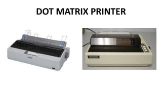
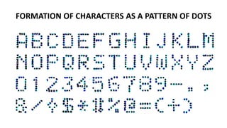
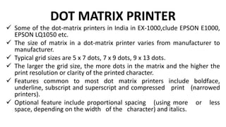
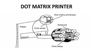
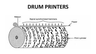
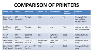
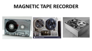
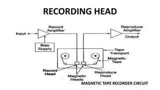
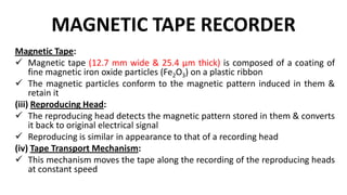
UNIT III
STORAGE AND DISPLAY
DEVICES
STORAGE AND DISPLAY DEVICES
• Magnetic disk and tape – Recorders, digital
plotters and printers, CRT display, digital CRO,
LED, LCD& dot matrix display – Data Loggers.
MAGNETIC TAPE RECORDER
 The major advantage of using a Magnetic Tape Recorder
Working Principle is that once the data is recorded, it can be
replayed an almost indefinite number of times.
 The recording period may vary from a few minutes to several
days.
 Speed translation of the data captured can be provided, i.e. fast
data can be slowed down and slow data speeded up by using
different record and reproduce speeds.
 Magnetic tape recorder, have a good response to high
frequency, i.e. they can be used to record high frequency
signals.
 Hence, magnetic tape recorders are widely used in
instrumentation systems.
BASIC COMPONENTS OF MAGNETIC TAPE RECORDER
Recording Head
Magnetic Head
Reproducing Head
Tape transport mechanism
Conditioning devices
RECORDING HEAD
 This device responds to an electrical signal in such a manner that a
magnetic pattern is created in a magnetizable medium
 A fine air gap of length 5-15 µm is shunted by passing the magnetic
tape
 A current in the coil causes a flux of the same shape to bridge the air
gap & hence to pass through the magnetic tape, thereby, magnetizing
the iron oxide (Fe2O3) particles as they pass the air gap
 The state of magnetization of the oxide as it leaves the air gap is
retained, thus the actual recording takes place at the trailing edge of
the gap
 Any signal recorded on the tape appears as a magnetic pattern
dispersed in space along the tape similar to the original coil current
variation with time
RECORDING HEAD
MAGNETIC TAPE RECORDER CIRCUIT
MAGNETIC TAPE RECORDER
Magnetic Tape:
 Magnetic tape (12.7 mm wide & 25.4 µm thick) is composed of a coating of
fine magnetic iron oxide particles (Fe2O3) on a plastic ribbon
 The magnetic particles conform to the magnetic pattern induced in them &
retain it
(iii) Reproducing Head:
 The reproducing head detects the magnetic pattern stored in them & converts
it back to original electrical signal
 Reproducing is similar in appearance to that of a recording head
(iv) Tape Transport Mechanism:
 This mechanism moves the tape along the recording of the reproducing heads
at constant speed
MAGNETIC TAPE RECORDER
 The tape mechanism must be capable of handling the tape during
various modes of operation without straining, distortion, or wearing out
the tape
 This requires that the mechanism must use arrangements to guide the
tape past the magnetic heads with great precision, maintain proper
tension, & obtain sufficient tape to magnetic head contact
 Arrangement for fast winding & reversing are also provided
 A capstan & pinch roller are used to drive the tape
(v) Conditioning Devices:
 These devices consist of amplifiers & filters required for modifying the
signal to a format that can be properly recorded on a tape
PRINCIPLE OF TAPE RECORDERS
 When a magnetic tape is passed through a recording head, the signal to be
recorded appears as some magnetic pattern on the tape.
 This magnetic pattern is in accordance with the variations of original recording
current.
 The recorded signal can be reproduced back by passing the same tape through
a reproducing head where the voltage is induced corresponding to the
magnetic pattern on the tape.
 When the tape is passed through the reproducing head, the head detects the
changes in the magnetic pattern i.e. magnetization.
 The change in magnetization of particles produces change in the reluctance of
the magnetic circuit of the reproducing head, inducing a voltage in its winding.
 The induced voltage depends on the direction of magnetisation and its
magnitude on the tape.
PRINCIPLE OF TAPE RECORDERS
 The emf, thus induced is proportional to the rate of change of magnitude of
magnetisation i.e. e N (di / dt)
 Where N = number of turns of the winding on reproducing head e = magnetic
flux produced.
 Suppose the signal to be recorded is Vm sin wt. Thus, the current in the
recording head and flux induced will be proportional to this voltage.
 It is given by e= k 1*Vm sin wt, where k1 = constant.
 Above pattern of flux is recorded on the tape. Now, when this tape is
passed through the reproducing head, above pattern is regenerated by
inducing voltage in the reproducing head winding.
 It is given by e= k2 *Vm cos wt
 Thus the reproducing signal is equal to derivative of input signal& it is
proportional to flux recorded & frequency of recorded signal.
METHODS OF RECORDING
 Direct Recording
 FM (Frequency Modulation) recording
 PDM (Pulse Duration Modulation) recording
 For instrumentation purposes mostly frequency modulation
recording is used.
 The pulse duration modulation recording is generally used in
the systems for special applications where large number of
slowly changing variables has to be recorded simultaneously.
TAPE MAGNETISATION CIRCUIT
X-Y RECORDER
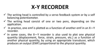
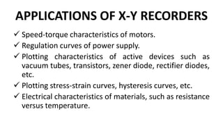
 XY Recorder Working – In most research fields, it is often
convenient to plot the instantaneous relationship between
two variables [Y = f(x)], rather than to plot each variable
separately as a function of time.
 In such cases, the X—Y recorder is used, in which one
variable is plotted against another variable. In an analog
X—Y recorder, the writing head is deflected in either the x-
direction or the y-direction on a fixed graph chart paper.
 The graph paper used is generally squared shaped, and is
held fixed by electrostatic attraction or by vacuum.
X-Y RECORDER
 The writing head is controlled by a servo feedback system or by a self
balancing potentiometer.
 The writing head consist of one or two pens, depending on the
application.
 In practice, one emf is plotted as a function of another emf in an X—Y
recorder.
 In some cases, the X—Y recorder is also used to plot one physical
quantity (displacement, force, strain, pressure, etc.) as a function of
another physical quantity, by using an appropriate transducer, which
produces an output (EMF) proportional to the physical quantity.
X-Y RECORDER
X-Y RECORDER
 In Figure, each of the input signals is attenuated in the range of 0-5 mV, so that it
can work in the dynamic range of the recorder. The balancing circuit then
compares the attenuated signal to a fixed internal reference voltage.
 The output of the balancing circuit is a dc error signal produced by the difference
between the attenuated signal and the reference voltage.
 This dc error signal is then converted into an ac signal with the help of a chopper
circuit.
 This ac signal is not sufficient to drive the pen/arm drive motor, hence, it is
amplified by an ac amplifier. This amplified signal (error signal) is then applied to
actuate the servo motor so that the pen/arm mechanism moves in an
appropriate direction in order to reduce the error, thereby bringing the system to
balance.
 Hence as the input signal being recorded varies, the pen/arm tries to hold the
system in balance, producing a record on the paper.
X-Y RECORDER
 The action described above takes place in both the axes simultaneously.
 Hence a record of one physical quantity with respect to another is obtained.
 Some X—Y recorders provides x and y input ranges which are continuously
variable between 0.25 mV/cm and 10 V/cm, with an accuracy of ± 0.1% of
the full scale. Zero offset adjustments are also provided.
 The dynamic performance of X—Y recorders is specified by their slewing rate
and acceleration. A very high speed X—Y recorder, capable of recording a
signal up to 10 Hz at an amplitude of 2 cm peak to peak, would have a
slewing rate of 97 cm/s and a peak acceleration of 7620 cm/s.
 An XY Recorder Working may have a sensitivity of 10 µV/mm, a slewing
speed of 1.5 ms and a frequency response of about 6 Hz for both the axis.
The chart size is about 250 x 180 mm. The accuracy of X—Y recorder is about
± 0.3%.
APPLICATIONS OF X-Y RECORDERS
 Speed-torque characteristics of motors.
 Regulation curves of power supply.
 Plotting characteristics of active devices such as
vacuum tubes, transistors, zener diode, rectifier diodes,
etc.
 Plotting stress-strain curves, hysteresis curves, etc.
 Electrical characteristics of materials, such as resistance
versus temperature.
Digital Plotters
DIGITAL PLOTTERS
Now a days , analog X-Y recorders are replaced
by digital X-Y recorder. It is known as digital
plotter
The main advantage is to increase the number of
measurement capabilities of the plotter.
In this plotter , the input is analog signal.
This is converted into digital .
DIGITAL PLOTTERS
This digital signal is stored in the memory and
indicates the time varying analog signal.
Then data in the memory can be scanned and
going to the any recorder or any display
device.
DIGITAL PLOTTERS
Advantage:
Output data can be plotted using multi-pen
plotting system
Plot or draw grids ,axis.
Simultaneous storage
Disadvantage:
Cost is high
PRINTERS
Printers can be classified according to their printing methodology
Impact printers and Non- impact printers.
 Impact printers press formed character faces against an inked
ribbon onto the paper.
 A Dot matrix printer ,Drum printer and chain / Band printers
are the examples of an impact printer.
 Non impact printer and plotters use laser techniques, inkjet
sprays, xerographic processes, electrostatic methods and
electrothermal methods to get images onto the paper.
 A ink-jet printer and laser printer are the examples of non-
impact printers.
IMPACT PRINTERS
A printer in which printing is the result of
mechanically striking the printing medium
An Impact printer makes contact with the
paper to produce an image
The impact may be produced by a print
hammer character, like that of a typewriter
key striking a ribbon against the paper
DOT MATRIX PRINTER
Dot matrix printers are also called serial
printers
These printers are characters printers, which
print one character at a time
They form characters and all kinds of images
as a pattern of dots
DOT MATRIX PRINTER
FORMATION OF CHARACTERS AS A PATTERN OF DOTS
DOT MATRIX PRINTER
 Figure shows how various types of characters can be formed
as a pattern of dots
 A dot-matrix printer has a print head, which move
horizontally (left to right and right to left) across the paper.
 The printer head contains an array of pins, which can be
activated independent of each other to extend and strike
against an inked ridden to form a pattern of dots on the
paper
 To print a character, the printer activates the approximate
set of pins as the print head moves horizontally
DOT MATRIX PRINTER
 Since dot matrix printers produce printed output as patterns of dots, they
can print any shape of character, which a programmer can describe
 This allows the printer to print many special characters, different sizes of
print, and the ability to print graphics, such as charts and graphs.
 Dot-matrix printers are impact printers, because they print by hammering
the pins on the inked ribbon to leave ink impressions on the paper.
 Hence they can be used to produce multiple copies by using carbon paper
or its equivalent.
 However due to impact printing, dot-matrix printers are noisy as
compared to non-impact printers.
 Dot-matrix printers are normally slow with speed ranging between 30 to
600 characters per second.
DOT MATRIX PRINTER
 Some of the dot-matrix printers in India in EX-1000,clude EPSON E1000,
EPSON LQ1050 etc.
 The size of matrix in a dot-matrix printer varies from manufacturer to
manufacturer.
 Typical grid sizes are 5 x 7 dots, 7 x 9 dots, 9 x 13 dots.
 The larger the grid size, the more dots in the matrix and the higher the
print resolution or clarity of the printed character.
 Features common to most dot matrix printers include boldface,
underline, subscript and superscript and compressed print (narrowed
printers).
 Optional feature include proportional spacing (using more or less
space, depending on the width of the character) and italics.
DOT MATRIX PRINTER
DOT MATRIX PRINTER
Advantage:
 Can print on multi-part forms or carbon copies.
 Low printing cost per page.
 Can be used on continuous form paper, useful for data logging.
 Reliable, durable.
Disadvantage:
 Noisy.
 Limited print quality.
 Low printing speed.
 Limited color printing.
DRUM PRINTERS
DRUM PRINTERS
 Drum printers are line printers which print one line at a time.
 It consists of a solid cylindrical drum with characters embossed
(raised characters) on its surface in the form of circular bands.
 Each band Consists of all the printing characters supported by
the printer in its character set, and the total number of bands is
equal to the maximum number of characters (print positions)
that can be printed on a line.
 Hence, a drum printer with 132 characters per line, and
supporting a character set of 96 characters, will have altogether
12,672 (132 x 96) characters embossed on its surface.
DRUM PRINTERS
 In addition to the drum, the printer has a set of hammers
mounted in front of the drum in a manner that an linked
ribbon and paper can be Placed between the hammers and the
drum.
 The total number of hammers is equal to the total number of
bands on the drum, that is, one hammer is located opposite to
each band of the drum.
 The drum rotates at a high speed, and a character at a print
position is Printed by activating the appropriate hammer, when
the character embossed on the band at the print position
passes below it.
DRUM PRINTERS
 The drum of a drum printer is expensive and cannot be
changed often.
 Hence , drum printers can only print a pre-defined set of
characters, in a pre-defined style, which is embossed on
the drum.
 Due to this reason, drum printers do not have the ability
to print any shape of characters, different sizes of print
and graphics such as charts and graphs
 Typical speeds of drum printers are in the range of 300 to
2000 lines per minute
CHAIN/BAND PRINTER
CHAIN/BAND PRINTER
These printers are also line printers
It Consists of a metallic chain/ band on which
all the characters of the characters set
supported by the printer are embossed.
The standard character set may have 48,64 or
96 characters
CHAIN/BAND PRINTER
 In addition to the chain/band the printer has a set of
hammers mounted in front of the chain/band in a manner
that an inked ribbon and paper can be placed between
the hammers and the chain/band
 The total number of hammers is equal to the total
number of print positions.
 Therefore , if there are 132 print positions , the printer
will have 132 hammers.
 Typical speed of chain/band printers are in the range of
400 to 3000 lines per minute.
NON-IMPACT PRINTERS
Printers that do no strike character against
ribbon or paper
Ink-jet printers
Laser printers
INK-JET PRINTERS
INK-JET PRINTERS
An inkjet printer creates an image by spraying
tiny droplets of ink onto the paper.
The print head moves back and forth as the
paper feeds through a set of rollers.
The complete image is built from many
minuscule dots, like the pixels on a TV or
phone screen.
INK-JET PRINTERS
 The quality of an image is determined by the number of dots per
inch (DPI) the printer is capable of producing.
 The lower range is acceptable for documents that consist
primarily of text and everyday graphics.
 However, for high-quality photos, the higher resolutions are
preferable.
 Yellow, magenta (red), cyan (blue), and black are the commonly
used ink colors in an inkjet printer. Used together, these can
reproduce most colors.
 Each ink color is usually contained in a separate replaceable
cartridge, but some models combine the inks into one cartridge.
LASER PRINTERS
LASER PRINTER
 The line, dot matrix, and ink jet printers need a head movement on a
ribbon to print characters.
 This mechanical movement is relatively slow due to the high inertia of
mechanical elements.
 In laser printers these mechanical movements are avoided.
 In these printers, an electronically controlled laser beam traces out the
desired character to be printed on a photoconductive drum.
 The exposed areas of the drum gets charged, which attracts an
oppositely charged ink from the ink toner on to the exposed areas.
 This image is then transferred to the paper which comes in contact with
the drum with pressure and heat.
LASER PRINTER
 The charge on the drum decides the darkness of the print.
 When charge is more, more ink is attracted and we get a dark
print.
 A colour laser printer works like a single colour laser printer,
except that the process is repeated four times with four different
ink colours:Cyan, magenta, yellow and black.
 Laser printers have high resolution from 600 dots per inch upto
1200 per inch.
 These printers print 4 to 16 page of text per minute.
 The high quality and speed of laser printers make them ideal for
office environment.
ADVANTAGES OF LASER PRINTER
 The main advantages of laser printers are speed, precision
and economy.
 A laser can move very quickly, so it can “ write” with much
greater speed than an inket.
 Because the laser beam has an unvarying diameter, it can
draw more precisely, without spilling any excess ink.
 Laser printers tend to be more expensive than ink-jet
printers, but it doesn’t cost as much to keep them running.
 Its toner power is cheap and lasts for longer time.
COMPARISON OF PRINTERS
Printer Type Speed Resolution Capital Cost Running Cost Drawing
Capability
Capacity
Drum and
Chain Printer
100
lines/min
Average High Low No Heavy duty. Can
take multiple
carbon copies
Dot Matrix
Printer
100
Char/sec
Average Low Low Poor Average can take 2
or 3 carbon copies
Ink Jet
printer
100
char/sec
Good 100
dot/cm
Low Higher than
dot matrix
Good Light duty. Single
copy
Laser Printer
(Low Speed)
10
pages/min
Good 120
dots/cm
Higher than
inkjet
Lower than
inkjet
Good Light duty. Single
copy.
Laser Printer
(High Speed)
10000
lines/min
Very good 600
dots/cm
High Low Good Heavy duty. Single
copy
CATHODE RAY OSCILLOSCOPE
 The cathode ray oscilloscope (CRO) is a type of electrical
instrument which is used for showing the measurement
and analysis of waveforms and others electronic and
electrical phenomenon.
 It is a very fast X-Y plotter shows the input signal versus
another signal or versus time.
 The CROs are used to analyze the waveforms, transient,
phenomena, and other time-varying quantities from a
very low-frequency range to the radio frequencies.
CATHODE RAY OSCILLOSCOPE
The cathode ray oscilloscope is probably the most
versatile tool for the development of electronic
circuit and systems
The cathode ray oscilloscope is a device that allows
the amplitude of electrical signal to be displayed
primarily as a function of time.
The oscilloscope depends on the movement of an
electron beam
CATHODE RAY OSCILLOSCOPE
 When the electron is injected through the electron gun, it passes
through the control grid.
 The control grid controls the intensity of electron in the vacuum
tube.
 If the control grid has high negative potential, then it allows only
a few electrons to pass through it.
 Thus, the dim spot is produced on the lightning screen.
 If the negative potential on the control grid is low, then the
bright spot is produced. Hence the intensity of light depends on
the negative potential of the control grid.
CATHODE RAY OSCILLOSCOPE
 After moving the control grid the electron beam passing through
the focusing and accelerating anodes.
 The accelerating anodes are at a high positive potential and
hence they converge the beam at a point on the screen.
 After moving from the accelerating anode, the beam comes
under the effect of the deflecting plates.
 When the deflecting plate is at zero potential, the beam
produces a spot at the centre.
 If the voltage is applied to the vertical deflecting plate, the
electron beam focuses at the upward and when the voltage is
applied horizontally the spot of light will be deflected
horizontally.
CATHODE RAY OSCILLOSCOPE
The major block circuit of general purpose CRO is as follow
 CRT
 Vertical Amplifier
 Delay line
 Horizontal amplifier
 Time base generator
 Trigger circuit
 Power supply
CATHODE RAY TUBE(CRT)
CRT DISPLAY
The device which allows, the amplitude of such signals, to be displayed
primarily as a function of time, is called cathode ray oscilloscope. The
cathode ray tube (CRT) is the heart of the C.R.O.
The CRT generates the electron beam, accelerates the beam, deflects the
beam and also has a screen where beam becomes visible as a spot.
The main parts of the CRT are
i) Electron gun
ii) Deflection system
iii) Fluorescent screen
iv) Glass tube or envelope
v) Base
ELECTRON GUN
 The electron gun section of the cathode ray tube provides a sharply
focused, electron beam directed towards the fluorescent-coated
screen.
 This section starts from thermally heated cathode, emitting the
electrons.
 The control grid is given negative potential with respect to cathode.
 This grid controls the number of electrons in the beam, going to the
screen.
 The momentum of the electrons (their number x their speed)
determines the intensity, or brightness, of the light emitted from the
fluorescent screen due to the electron bombardment.
 The light emitted is usually of the green colour.
DEFLECTION SYSTEM
When the electron beam is accelerated it
passes through the deflection system, with
which beam can be positioned anywhere on
the screen.
FLUORESCENT SCREEN
 The light produced by the screen does not disappear immediately when
bombardment by electrons ceases, i.e., when the signal becomes zero.
 The time period for which the trace remains on the screen after the
signal becomes zero is known as “persistence or fluorescence” .
 The persistence may be as short as a few microsecond, or as long as
tens of seconds or even minutes.
 Medium persistence traces are mostly used for general purpose
applications.
 Long persistence traces are used in the study of transients.
 Long persistence helps in the study of transients since the trace is still
seen on the screen after the transient has disappeared.
GLASS TUBE
All the components of a CRT are enclosed in
an evacuated glass tube called envelope.
This allows the emitted electrons to move
about freely from one end of the tube to the
The base is provided to the CRT through which
the connections are made to the various
parts. other end.
POWER SUPPLY
 There are two power supplies, a —ve High Voltage (HV)
supply and a +ve Low Voltage (LV) supply.
 Two voltages are generated in the CRO.
 The +ve volt supply is from + 300 to 400 V. The —ve high
voltage supply is from — 1000 to — 1500 V.
 This voltage is passed through a bleeder resistor at a few
mA.
 The intermediate voltages are obtained from the bleeder
resistor for intensity, focus and positioning controls.
APPLICATIONS
 The CRO’s are used in huge applications like radio stations for observing the
transmitting & receiving the properties of the signal.
 The CRO is used to measure the voltage, current, frequency, inductance,
admittance, resistance, and power factor.
 This device is also used to check the AM and FM circuits characteristics
 This device is used to monitor the signal properties as well as characteristics
and also controls the analog signals.
 The CRO is used through the resonance circuit to view the shape of the signal,
bandwidth, etc.
 Used for comparing phase & frequency
 It is used in TV, Radar, and analysis of engine pressure
 To check the reactions of nervous and heartbeat.
 In the hysteresis loop, it is used to find BH curves
 Transistor curves can be traced.
ADVANTAGES
 Cost and Timeline
 Training requirements
 Consistency & quality
 Time efficiency
 Expertise & experience
 Capacity for problem-solving
 Hassle-free
 Assurance for regulatory compliance
 Voltage measurement
 Current measurement
 Examination of waveform
 Measurement of phase and frequency
DISADVANTAGES
These oscilloscopes are expensive as compared
with other measuring devices like multimeters.
They are complicated to repair once it gets
damaged.
These devices need complete isolation
These are huge, heavy and uses more power
A lot of control terminals
DIGITAL STORAGE OSCILLOSCOPE (DSO)
DIGITAL STORAGE OSCILLOSCOPE
 The input signal is applied to the amplifier and attenuator
section.
 The oscilloscope uses same type of amplifier and attenuator
circuitry as used in the conventional oscilloscopes.
 The attenuated signal is then applied to the vertical amplifier.
 To digitize the analog signal, analog to digital (A/D) converter
is used.
 The output of the vertical amplifier is applied to the A/D
converter section.
 The successive approximation type of A/D converter is most
often used in the digital storage oscilloscopes.
DIGITAL STORAGE OSCILLOSCOPE
 The sampling rate and memory size are selected depending upon
the duration& the waveform to be recorded.
 Once the input signal is sampled, the A/D converter digitizes it.
 The signal is then captured in the memory.
 Once it is stored in the memory, many manipulations are possible
as memory can be readout without being erased.
 The digital storage oscilloscope has three modes:
1. Roll mode
2. Store mode
3. Hold or save mode.
ADVANTAGES
i) It is easier to operate and has more capability.
ii) The storage time is infinite.
iii) The display flexibility is available. The number of traces
that can be stored and recalled depends on the size of the
memory.
iv) The cursor measurement is possible.
v) The characters can be displayed on screen along with the
waveform which can indicate waveform information such as
minimum, maximum, frequency, amplitude etc.
ADVANTAGES
vi) The X-Y plots, B-H curve, P-V diagrams can be displayed.
vii) The pretrigger viewing feature allows to display the
waveform before trigger pulse.
viii) Keeping the records is possible by transmitting the data
to computer system where the further processing is possible
ix) Signal processing is possible which includes translating
the raw data into finished information e.g. computing
parameters of a captured signal like r.m.s. value, energy
stored etc.
LIGHT EMITTING DIODE (LED)
A PN junction which emits light when forward
biased
The emitted light may be visible or invisible
The amount of light output is directly
proportional to the forward current, thus higher
the forward current, higher is the light output
LIGHT EMITTING DIODE (LED)
 The Light Emitting Diodes, Figure(a) is basically a
semiconductor PN junction diode capable of emitting
electromagnetic radiation under forward conductions.
 The radiation emitted by LEDs can be either in the visible
spectrum or in the infrared region, depending on the type of
the semiconductor material used.
 Generally, infra-red emitting LED’s are coated with Phosphor
so that, by the excitation of phosphor visible light can be
produced.
 LEDs are useful for electronics display and instrumentation.
 Figure (b) shows the symbol of an LED.
LIGHT EMITTING DIODE (LED)
HOW DOES THE LIGHT EMITTING DIODE WORK?
 The light-emitting diode simply, we know as a diode.
 When the diode is forward biased, then the electrons &
holes are moving fast across the junction and they are
combined constantly, removing one another out.
 Soon after the electrons are moving from the n-type to
the p-type silicon, it combines with the holes, then it
disappears.
 Hence it makes the complete atom & more stable and it
gives the little burst of energy in the form of a tiny packet
or photon of light.
THE ADVANTAGE OF USING LEDS IN ELECTRONIC
DISPLAYS ARE AS FOLLOWS.
 LEDs are very small devices, and can be considered as point sources
of They can therefore be stacked in a high-density matrix to serve as a
numeric and alphanumeric display.
 They can have a character density of several thousand per square
meter.
 The light output from an LED is function of the current flowing
through an LED can therefore, be smoothly controlled by varying the
current.
 This is particularly useful for operating LED displays under different
ambient lighting conditions.
THE ADVANTAGE OF USING LEDS IN ELECTRONIC
DISPLAYS ARE AS FOLLOWS.
LEDs are highly efficient emitters of EM radiation. LEDs
with light output of different colors, i.e. red, amber,
green and yellow are commonly available.
LEDs are very fast devices, having a turn ON-OFF time
of less than 1 ns.
The low supply voltage and current requirements of
LEDs make them compatible with DTL and TTL, ICs.
LIGHT EMITTING DIODE (LED)
 In germanium and silicon semiconductors, most of the energy
is released in the form of heat.
 In Gallium Phosphide (GaP) and Gallium Arsenide Phosphide
(GaAsP) most of the emitted photons have their wavelengths
in the visible regions, and therefore these semiconductors are
used for the construction of LEDs.
 The color of light emitted depends upon the semiconductor
material and doping level.
DIFFERENT MATERIALS USED FOR DOPING GIVE
OUT DIFFERENT COLOURS.
Gallium Arsenide (GaAs) — red
Gallium Arsenide Phosphide (GaAsP) — red or
yellow
Gallium Phosphide (GaP) — red or green
ADVANTAGES
Low power consumption.
Very fast action.
Very small size and weight.
Extremely long life.
Operating voltage and current is less.
Variety of spectrum output colors.
No effect due to mechanical vibrations.
DISADVANTAGES
Low efficiency
Radiated output power is temperature
dependent
High power consumption compared to LCD
Very sensitive device
APPLICATIONS
In power indicator to indicate power ON/OFF
conditions.
Displays of numeric and alphanumeric
characters
In optical switching conditions
Decorating instrumentation
DIFFERENCE BETWEEN A DIODE AND A LED
DIODE LED
The semiconductor device like a diode conducts simply in
one direction.
The LED is one type of diode, used to generate light
The designing of the diode can be done with a
semiconductor material & the flow of electrons in this
material can give their energy the heat form.
The LED is designed with the gallium Phosphide & gallium
arsenide whose electrons can generate light while
transmitting the energy.
The diode changes the AC into the DC The LED changes the voltage into light
It has a high reverse breakdown voltage
It has a low-reverse breakdown voltage.
The on-state voltage of the diode is 0.7v for silicon
whereas, for germanium, it is 0.3v
The on-state voltage of LED approximately ranges from
1.2 to 2.0 V.
The diode is used in voltage rectifiers, clipping & clamping
circuits, voltage multipliers.
The applications of LED are traffic signals, automotive
headlamps, in medical devices, camera flashes, etc.
LIQUID CRYSTAL DISPLAY
 LCD are passive type display devices used for display of
numeric and alphanumeric character in dot matrix and
segmental display
 The main advantage of LCD is the low power
consumption because no light generation is required
 Two types of LCD’s are
1.Dynamic Scattering type
2.Field effect type
LIQUID CRYSTAL DISPLAY
 The molecules in ordinary liquids normally have random
orientations
 In liquid crystals the molecules are oriented in a definite
crystal pattern shown in figure
 When an electric field is applied to the liquid crystal , the
molecules align perpendicular to the field charge carriers
 The molecules turbulence causes the light to scattered in
all directions so that the activated areas appear bright.
 This Phenomena is known as “ Dynamic Scattering”
CONSTRUCTION OF LCD
LIQUID CRYSTAL DISPLAY
Reflective twisted nematic liquid crystal display.
1. Polarizing filter film with a vertical axis to polarize
light as it enters.
2. Glass substrate with ITO electrodes. The shapes
of these electrodes will determine the shapes that
will appear when the LCD is turned ON. Vertical
ridges etched on the surface are smooth.
3. Twisted nematic liquid crystal.
LIQUID CRYSTAL DISPLAY
4. Glass substrate with common electrode film (ITO)
with horizontal ridges to line up with the horizontal
filter.
5. Polarizing filter film with a horizontal axis to
block/pass light.
6. Reflective surface to send light back to viewer. (In
a backlit LCD, this layer is replaced with a light
source.)
LIQUID CRYSTAL DISPLAY
 A liquid crystal display (LCD) is a thin, flat electronic visual
display that uses the light modulating properties of liquid
crystals (LCs).
 LCs do not emit light directly.
 They are used in a wide range of applications including:
computer monitors, television, instrument panels, aircraft
cockpit displays, signage, etc.
 They are common in consumer devices such as video
players, gaming devices, clocks, watches, calculators, and
telephones.
LIQUID CRYSTAL DISPLAY
 LCDs have displaced cathode ray tube (CRT) displays in
most applications. They are usually more compact,
lightweight, portable, less expensive, more reliable,
and easier on the eyes.
 They are available in a wider range of screen sizes than
CRT and plasma displays, and since they do not use
phosphors, they cannot suffer image burn-in. LCDs are
more energy efficient and offer safer disposal than
CRTs.
LCD ALARM CLOCK
 Each pixel of an LCD typically consists of a layer of molecules aligned
between two transparent electrodes, and two polarizing filters, the axes of
transmission of which are (in most of the cases) perpendicular to each
other.
 With no actual liquid crystal between the polarizing filters, light passing
through the first filter would be blocked by the second (crossed) polarizer.
In most of the cases the liquid crystal has double refraction.
COMPARISON OF LCD, EDGE LIT LED AND
LED TV
 LED-backlight LCD television (incorrectly called LED TV by (CCFLs) used in
traditional
 LCD televisions. This has a dramatic impact resulting in a thinner panel
and less power consumption, brighter display with better contrast
levels.
 It also generates less heat than regular LCD TVs.
 The LEDs can come in three forms: dynamic RGB LEDs which are
positioned behind the panel, white Edge-LEDs positioned around the rim
of the screen which use a special diffusion panel to spread the light
evenly behind the screen (the most common) and full-array which are
arranged behind the screen but they are incapable of dimming or
brightening individually
ADVANTAGES AND DISADVANTAGES
ADVANTAGES
 Low cost
 Low Power Consumption
 It required very low voltage
DISADVANTAGES
 Life time is very less compared to LED
 Response time is more compared to LED
 They occupy large area
 Reliability is quite low
APPLICATIONS
Digital watches to indicate time , day and date
Etc.,
Electronic toys and calculators
Instrument display
COMPARISON OF LCD AND LED
LED LCD
It consumes more power (in mW) It consumes less power(µW)
Life time is more Life time is less
High cost Low cost
Capable of generating its own light Requires an external or internal light
sources
Emitting colour depends upon the
material used.
Monochrome in nature
It emits light energy when energized It will alter the externally available
illumination
SEGMENTAL AND DOT MATIX DISPLAY
Segmental display:
Two types
1.Segmented gas discharge display
2.Segmental LCD and LED display
SEVEN SEGMENTED GAS DISCHARGE DISPLAY
 Segmental gas discharge display work on the principle of gas
discharge glow
 They are mostly available in 7 segment or 14 segment form, to
display numeric and alphanumeric characters.
 Each segment (decimal point) of the 7 segment display formed
on a base has a separate cathode.
 The anode is common to each member of the 7 segment group
which is deposited on the covering face plate.
 The space between the anodes and cathodes contains the gas.
 For each group of segments, a ‘keep alive’ cathode is also
provided.
SEVEN SEGMENTED GAS DISCHARGE DISPLAY
 For improving the switching speeds of the display a small constant
current (a few micro amps) is passed through this keep alive cathode,
which acts as a source of ions.
 Pins are connected to the electrodes at the rear of the base plate, with
the help of which external connections can be made.
 The major disadvantage of this gas discharge tube is that high voltage is
required for operating it.
 Therefore, high voltage transistors, in the range of 150 — 200 V, are
required as switches for the cathodes.
 A major advantage is that the power consumed is extremely small,
because a bright display can be obtained even for currents as low as
200 μA.
SEVEN SEGMENTED GAS DISCHARGE DISPLAY
 The device uses a glass substrate, shown in Fig. Back electrodes of the
thick film type serve as cathode segments, and front electrodes of the
thin film type serve as transparent anodes.
 A gas, typically neon, is filled in the discharge space between the
cathode and anode segment.
 The gas is struck between the cathode and anode of a chosen segment
so that the cathode glow provides the illumination
 All numeric characters can be displayed by activating the appropriate
segment.
 Display panels of rows or columns of such characters can be easily
constructed by extending a single character.
 The power requirements of such devices are more or less in the same
range as those for Nixie tubes.
SEVEN SEGMENT DISPLAY USING LEDS
 In Seven Segment Display Using LEDs, it is usual to
employ a single LED for each segment.
 For conventional 7 segment LED displays (including the
decimal point, i.e. the 8th segment), the wiring pattern is
simplified by making one terminal common to all LEDs
and other terminals corresponding to different segments.
 The terminals can be either of the common anode (CA)
form or common cathode (CC) form, shown in Figs (b)
and (c).
SEVEN SEGMENT DISPLAY USING LEDS
Both multi digit and segmental displays
require a code converter
One code converter per character for static
display systems and a single code converter
for time shared and multiplexed dynamic
display systems, which illuminated at a time
MULTI DIGIT DISPLAY SYSTEM USING LED
SEVEN SEGMENT DISPLAY USING LEDS
 Multi-digit display system may be static or dynamic.
 Common anode type displays require an active low (or current
sinking) configuration for code converter circuitry, whereas an
active high (or current sourcing) output circuit is necessary for
common-cathode LED type display.
 Both multi-digit and Seven Segment Display Using LEDs require a
code converter; one code converter per character for static display
systems and a single code converter for time shared and
multiplexed dynamic display systems, which are illuminated one at
a time.
 The typical circuit schemes described in the figures are only of the
decimal numeric character.
SEVEN SEGMENT DISPLAY USING LEDS
 An 8 digit display system, operating on this principle
and suitable for digital instrumentation is given in Fig.
(d).
 It is also possible to generate hexadecimal numeric
characters and conventional alphanumeric characters
using 7 segment and 14 or 16 segment LED display
units respectively, with a proper code converter.
 Both static and dynamic displays can be realized using
LCDs, either in a common format
DOT MATRIX DISPLAYS
DOT MATRIX DISPLAYS
Excellent alphanumeric characters can be
displayed by using dot matrix LEDs with an
LED at each dot location.
Commonly used Dot Matrix Displays of
prominent characters are 5 x 7, 5 x 8, and 7 x
9, of which 5 x 7 shown in Fig.(a), is very
popular due to economic considerations.
DOT MATRIX DISPLAYS
The two wiring patterns of dot matrix displays are
as follows.
Common anode or common cathode connection
(uneconomical).
X — Y array connection (economical and can be
extended vertically or horizontally using a
minimum number of wires, Fig. (b)).
DATA LOGGER
DATA LOGGER
Data Logger Operation – For proper
understanding of a Data Logger Operation, it is
essential to understand the difference between
analog and digital signals.
For example, measurement of temperature by a
milli voltmeter, whose needle shows a reading
directly proportional to the emf generated by the
thermocouple , is an analog signal.
DATA LOGGER
 However, digital equipment presents a digital output in terms of pulses
and involves an electronic pulse counting equipment which counts the
number of pulses.
 The pulses are generated such that each pulse corresponds to the
smallest value of the parameter being measured.
 These digital signals are precise at all times. Consider the example of
temperature.
 In the case of analog measurements even the accuracy of the
potentiometric method is limited by the precision with which the
resistance can be subdivided.
 In the digital method, the electrical signal obtained from the
thermocouple is subdivided by an electronic decade circuit and thus the
thermocouple voltage can be measured to many places of decimal.
DATA LOGGER
Basic parts of a Data Logger Operation
Input scanner
Signal conditioner
A/D converter
Recording equipment
Programmer
DATA LOGGER
Input Signals
The input signals fed to the input scanner of the Data Logger Operation can be of
the following types.
 High level signals from pressure transducers
 Low level signals from thermocouples
 ac signals
 Pneumatic signals from pneumatic transducers
 On/off signals from switches, relays, etc.
 Pulse train from tachometer
 Digital quantities
The last three signals (5, 6 and 7) are of the digital type and are handled by
one set of input scanners and the remaining signals are of the analog type and
are handled by a different set of input scanner.
INPUT SCANNERS
 The scanner select each input signal in turn, the Data
Logger Operation requires only one signal amplifier
and conditioner, one A/D converter and a single
recorder.
 Modern scanners have input scanners which can scan
at the rate of 150 inputs/s, but the rate of scanning has
to be matched with the rate of change of input data,
and the time required by the recorder and the output
devices to print one output.
SIGNAL CONDITIONING
The signal can be linearised at any one of the following three places.
 In the analog stage before conversion
 In the conversion process
 Digitally after conversion
The first method is not suited to low level voltages, as it requires
some form of amplification. The signal conditioner may be placed
between the scanner and the converter. But, each type of
transducer requires individual linearising circuits.
The third method requires a storage capability and a computer
processing technique. The most satisfactory is the second
method, whereby linearization is built into the conversion
process.
A/D CONVERTERS
The converter converts analog signal to digital
signal.
RECORDERS
The output from the Data Logger Operation can
be printed on any of the following.
Typewriter
Strip printer and/or digitally recorded on
punched tape or magnetic tape for further
analysis in a digital computer.
PROGRAMMER
 This can be considered as an automatic sequence switch which
controls the operation of all other units of the data logger. The
sequential operations performed by a programmer are as
follows.
 Set amplifier gain for individual input, i.e. gain of the amplifier
has to be so adjusted that for a maximum value of input signal,
the A/D converter records a full scale reading.
 Set linearization factor so that the adjusted output from the
signal amplifier is directly proportional to the measured
quantity.
 Set high and low alarm limit
 Initiate alarm for abnormal condition
PROGRAMMER
 Select input signal scanner switching is set normally by a timing pulse to
select the reset input.
 Start A/D conversion
 Record reading channel identify and time (in order that the readings
may be identified at a later stage, a number identifying that
the input has been normally recorded, with the actual reading and the
time during the beginning of each complete scan).
 Display reading
 Reset logger. (At the end of cycle the A/D converter sections of the
logger are reset to their initial conditions and the cycle, starts again.)
DATA LOGGER
Monitoring stress and strain in large mechanical
structures such as bridges, steel framed buildings,
towers, launch pads etc.
Monitoring environmental parameters in
temperature and environmental chambers and
test facilities.
A data logger is a self-contained unit that does
not require a host to operate.
ADVANTAGES
 A data logger is an attractive alternative to either a recorder or
data acquisition system in many applications. When compared
to a recorder, data loggers have the ability to accept a greater
number of input channels, with better resolution and accuracy.
 Also, data loggers usually have some form of on-board
intelligence, which provides the user with diverse capabilities.
 For example, raw data can be analyzed to give flow rates,
differential temperatures, and other interpreted data that
otherwise would require manual analysis by the operator the
operator has a permanent recording on paper,
ADVANTAGES
No other external or peripheral equipment is
required for operation, and
Many data loggers of this type also have the ability
to record data trends, in addition to simple digital
data recording
Applications
Temperature sensor
Pressure sensor

storage and display devices

  • 1.
    UNIT III STORAGE ANDDISPLAY DEVICES
  • 2.
    STORAGE AND DISPLAYDEVICES • Magnetic disk and tape – Recorders, digital plotters and printers, CRT display, digital CRO, LED, LCD& dot matrix display – Data Loggers.
  • 3.
  • 4.
    MAGNETIC TAPE RECORDER The major advantage of using a Magnetic Tape Recorder Working Principle is that once the data is recorded, it can be replayed an almost indefinite number of times.  The recording period may vary from a few minutes to several days.  Speed translation of the data captured can be provided, i.e. fast data can be slowed down and slow data speeded up by using different record and reproduce speeds.  Magnetic tape recorder, have a good response to high frequency, i.e. they can be used to record high frequency signals.  Hence, magnetic tape recorders are widely used in instrumentation systems.
  • 5.
    BASIC COMPONENTS OFMAGNETIC TAPE RECORDER Recording Head Magnetic Head Reproducing Head Tape transport mechanism Conditioning devices
  • 6.
    RECORDING HEAD  Thisdevice responds to an electrical signal in such a manner that a magnetic pattern is created in a magnetizable medium  A fine air gap of length 5-15 µm is shunted by passing the magnetic tape  A current in the coil causes a flux of the same shape to bridge the air gap & hence to pass through the magnetic tape, thereby, magnetizing the iron oxide (Fe2O3) particles as they pass the air gap  The state of magnetization of the oxide as it leaves the air gap is retained, thus the actual recording takes place at the trailing edge of the gap  Any signal recorded on the tape appears as a magnetic pattern dispersed in space along the tape similar to the original coil current variation with time
  • 7.
  • 8.
    MAGNETIC TAPE RECORDER MagneticTape:  Magnetic tape (12.7 mm wide & 25.4 µm thick) is composed of a coating of fine magnetic iron oxide particles (Fe2O3) on a plastic ribbon  The magnetic particles conform to the magnetic pattern induced in them & retain it (iii) Reproducing Head:  The reproducing head detects the magnetic pattern stored in them & converts it back to original electrical signal  Reproducing is similar in appearance to that of a recording head (iv) Tape Transport Mechanism:  This mechanism moves the tape along the recording of the reproducing heads at constant speed
  • 9.
    MAGNETIC TAPE RECORDER The tape mechanism must be capable of handling the tape during various modes of operation without straining, distortion, or wearing out the tape  This requires that the mechanism must use arrangements to guide the tape past the magnetic heads with great precision, maintain proper tension, & obtain sufficient tape to magnetic head contact  Arrangement for fast winding & reversing are also provided  A capstan & pinch roller are used to drive the tape (v) Conditioning Devices:  These devices consist of amplifiers & filters required for modifying the signal to a format that can be properly recorded on a tape
  • 10.
    PRINCIPLE OF TAPERECORDERS  When a magnetic tape is passed through a recording head, the signal to be recorded appears as some magnetic pattern on the tape.  This magnetic pattern is in accordance with the variations of original recording current.  The recorded signal can be reproduced back by passing the same tape through a reproducing head where the voltage is induced corresponding to the magnetic pattern on the tape.  When the tape is passed through the reproducing head, the head detects the changes in the magnetic pattern i.e. magnetization.  The change in magnetization of particles produces change in the reluctance of the magnetic circuit of the reproducing head, inducing a voltage in its winding.  The induced voltage depends on the direction of magnetisation and its magnitude on the tape.
  • 11.
    PRINCIPLE OF TAPERECORDERS  The emf, thus induced is proportional to the rate of change of magnitude of magnetisation i.e. e N (di / dt)  Where N = number of turns of the winding on reproducing head e = magnetic flux produced.  Suppose the signal to be recorded is Vm sin wt. Thus, the current in the recording head and flux induced will be proportional to this voltage.  It is given by e= k 1*Vm sin wt, where k1 = constant.  Above pattern of flux is recorded on the tape. Now, when this tape is passed through the reproducing head, above pattern is regenerated by inducing voltage in the reproducing head winding.  It is given by e= k2 *Vm cos wt  Thus the reproducing signal is equal to derivative of input signal& it is proportional to flux recorded & frequency of recorded signal.
  • 12.
    METHODS OF RECORDING Direct Recording  FM (Frequency Modulation) recording  PDM (Pulse Duration Modulation) recording  For instrumentation purposes mostly frequency modulation recording is used.  The pulse duration modulation recording is generally used in the systems for special applications where large number of slowly changing variables has to be recorded simultaneously.
  • 13.
  • 14.
    X-Y RECORDER  XYRecorder Working – In most research fields, it is often convenient to plot the instantaneous relationship between two variables [Y = f(x)], rather than to plot each variable separately as a function of time.  In such cases, the X—Y recorder is used, in which one variable is plotted against another variable. In an analog X—Y recorder, the writing head is deflected in either the x- direction or the y-direction on a fixed graph chart paper.  The graph paper used is generally squared shaped, and is held fixed by electrostatic attraction or by vacuum.
  • 15.
    X-Y RECORDER  Thewriting head is controlled by a servo feedback system or by a self balancing potentiometer.  The writing head consist of one or two pens, depending on the application.  In practice, one emf is plotted as a function of another emf in an X—Y recorder.  In some cases, the X—Y recorder is also used to plot one physical quantity (displacement, force, strain, pressure, etc.) as a function of another physical quantity, by using an appropriate transducer, which produces an output (EMF) proportional to the physical quantity.
  • 16.
  • 17.
    X-Y RECORDER  InFigure, each of the input signals is attenuated in the range of 0-5 mV, so that it can work in the dynamic range of the recorder. The balancing circuit then compares the attenuated signal to a fixed internal reference voltage.  The output of the balancing circuit is a dc error signal produced by the difference between the attenuated signal and the reference voltage.  This dc error signal is then converted into an ac signal with the help of a chopper circuit.  This ac signal is not sufficient to drive the pen/arm drive motor, hence, it is amplified by an ac amplifier. This amplified signal (error signal) is then applied to actuate the servo motor so that the pen/arm mechanism moves in an appropriate direction in order to reduce the error, thereby bringing the system to balance.  Hence as the input signal being recorded varies, the pen/arm tries to hold the system in balance, producing a record on the paper.
  • 18.
    X-Y RECORDER  Theaction described above takes place in both the axes simultaneously.  Hence a record of one physical quantity with respect to another is obtained.  Some X—Y recorders provides x and y input ranges which are continuously variable between 0.25 mV/cm and 10 V/cm, with an accuracy of ± 0.1% of the full scale. Zero offset adjustments are also provided.  The dynamic performance of X—Y recorders is specified by their slewing rate and acceleration. A very high speed X—Y recorder, capable of recording a signal up to 10 Hz at an amplitude of 2 cm peak to peak, would have a slewing rate of 97 cm/s and a peak acceleration of 7620 cm/s.  An XY Recorder Working may have a sensitivity of 10 µV/mm, a slewing speed of 1.5 ms and a frequency response of about 6 Hz for both the axis. The chart size is about 250 x 180 mm. The accuracy of X—Y recorder is about ± 0.3%.
  • 19.
    APPLICATIONS OF X-YRECORDERS  Speed-torque characteristics of motors.  Regulation curves of power supply.  Plotting characteristics of active devices such as vacuum tubes, transistors, zener diode, rectifier diodes, etc.  Plotting stress-strain curves, hysteresis curves, etc.  Electrical characteristics of materials, such as resistance versus temperature.
  • 20.
  • 21.
    DIGITAL PLOTTERS Now adays , analog X-Y recorders are replaced by digital X-Y recorder. It is known as digital plotter The main advantage is to increase the number of measurement capabilities of the plotter. In this plotter , the input is analog signal. This is converted into digital .
  • 22.
    DIGITAL PLOTTERS This digitalsignal is stored in the memory and indicates the time varying analog signal. Then data in the memory can be scanned and going to the any recorder or any display device.
  • 23.
    DIGITAL PLOTTERS Advantage: Output datacan be plotted using multi-pen plotting system Plot or draw grids ,axis. Simultaneous storage Disadvantage: Cost is high
  • 24.
    PRINTERS Printers can beclassified according to their printing methodology Impact printers and Non- impact printers.  Impact printers press formed character faces against an inked ribbon onto the paper.  A Dot matrix printer ,Drum printer and chain / Band printers are the examples of an impact printer.  Non impact printer and plotters use laser techniques, inkjet sprays, xerographic processes, electrostatic methods and electrothermal methods to get images onto the paper.  A ink-jet printer and laser printer are the examples of non- impact printers.
  • 25.
    IMPACT PRINTERS A printerin which printing is the result of mechanically striking the printing medium An Impact printer makes contact with the paper to produce an image The impact may be produced by a print hammer character, like that of a typewriter key striking a ribbon against the paper
  • 26.
    DOT MATRIX PRINTER Dotmatrix printers are also called serial printers These printers are characters printers, which print one character at a time They form characters and all kinds of images as a pattern of dots
  • 27.
  • 28.
    FORMATION OF CHARACTERSAS A PATTERN OF DOTS
  • 29.
    DOT MATRIX PRINTER Figure shows how various types of characters can be formed as a pattern of dots  A dot-matrix printer has a print head, which move horizontally (left to right and right to left) across the paper.  The printer head contains an array of pins, which can be activated independent of each other to extend and strike against an inked ridden to form a pattern of dots on the paper  To print a character, the printer activates the approximate set of pins as the print head moves horizontally
  • 30.
    DOT MATRIX PRINTER Since dot matrix printers produce printed output as patterns of dots, they can print any shape of character, which a programmer can describe  This allows the printer to print many special characters, different sizes of print, and the ability to print graphics, such as charts and graphs.  Dot-matrix printers are impact printers, because they print by hammering the pins on the inked ribbon to leave ink impressions on the paper.  Hence they can be used to produce multiple copies by using carbon paper or its equivalent.  However due to impact printing, dot-matrix printers are noisy as compared to non-impact printers.  Dot-matrix printers are normally slow with speed ranging between 30 to 600 characters per second.
  • 31.
    DOT MATRIX PRINTER Some of the dot-matrix printers in India in EX-1000,clude EPSON E1000, EPSON LQ1050 etc.  The size of matrix in a dot-matrix printer varies from manufacturer to manufacturer.  Typical grid sizes are 5 x 7 dots, 7 x 9 dots, 9 x 13 dots.  The larger the grid size, the more dots in the matrix and the higher the print resolution or clarity of the printed character.  Features common to most dot matrix printers include boldface, underline, subscript and superscript and compressed print (narrowed printers).  Optional feature include proportional spacing (using more or less space, depending on the width of the character) and italics.
  • 32.
  • 33.
    DOT MATRIX PRINTER Advantage: Can print on multi-part forms or carbon copies.  Low printing cost per page.  Can be used on continuous form paper, useful for data logging.  Reliable, durable. Disadvantage:  Noisy.  Limited print quality.  Low printing speed.  Limited color printing.
  • 34.
  • 35.
    DRUM PRINTERS  Drumprinters are line printers which print one line at a time.  It consists of a solid cylindrical drum with characters embossed (raised characters) on its surface in the form of circular bands.  Each band Consists of all the printing characters supported by the printer in its character set, and the total number of bands is equal to the maximum number of characters (print positions) that can be printed on a line.  Hence, a drum printer with 132 characters per line, and supporting a character set of 96 characters, will have altogether 12,672 (132 x 96) characters embossed on its surface.
  • 36.
    DRUM PRINTERS  Inaddition to the drum, the printer has a set of hammers mounted in front of the drum in a manner that an linked ribbon and paper can be Placed between the hammers and the drum.  The total number of hammers is equal to the total number of bands on the drum, that is, one hammer is located opposite to each band of the drum.  The drum rotates at a high speed, and a character at a print position is Printed by activating the appropriate hammer, when the character embossed on the band at the print position passes below it.
  • 37.
    DRUM PRINTERS  Thedrum of a drum printer is expensive and cannot be changed often.  Hence , drum printers can only print a pre-defined set of characters, in a pre-defined style, which is embossed on the drum.  Due to this reason, drum printers do not have the ability to print any shape of characters, different sizes of print and graphics such as charts and graphs  Typical speeds of drum printers are in the range of 300 to 2000 lines per minute
  • 38.
  • 39.
    CHAIN/BAND PRINTER These printersare also line printers It Consists of a metallic chain/ band on which all the characters of the characters set supported by the printer are embossed. The standard character set may have 48,64 or 96 characters
  • 40.
    CHAIN/BAND PRINTER  Inaddition to the chain/band the printer has a set of hammers mounted in front of the chain/band in a manner that an inked ribbon and paper can be placed between the hammers and the chain/band  The total number of hammers is equal to the total number of print positions.  Therefore , if there are 132 print positions , the printer will have 132 hammers.  Typical speed of chain/band printers are in the range of 400 to 3000 lines per minute.
  • 41.
    NON-IMPACT PRINTERS Printers thatdo no strike character against ribbon or paper Ink-jet printers Laser printers
  • 42.
  • 43.
    INK-JET PRINTERS An inkjetprinter creates an image by spraying tiny droplets of ink onto the paper. The print head moves back and forth as the paper feeds through a set of rollers. The complete image is built from many minuscule dots, like the pixels on a TV or phone screen.
  • 44.
    INK-JET PRINTERS  Thequality of an image is determined by the number of dots per inch (DPI) the printer is capable of producing.  The lower range is acceptable for documents that consist primarily of text and everyday graphics.  However, for high-quality photos, the higher resolutions are preferable.  Yellow, magenta (red), cyan (blue), and black are the commonly used ink colors in an inkjet printer. Used together, these can reproduce most colors.  Each ink color is usually contained in a separate replaceable cartridge, but some models combine the inks into one cartridge.
  • 45.
  • 46.
    LASER PRINTER  Theline, dot matrix, and ink jet printers need a head movement on a ribbon to print characters.  This mechanical movement is relatively slow due to the high inertia of mechanical elements.  In laser printers these mechanical movements are avoided.  In these printers, an electronically controlled laser beam traces out the desired character to be printed on a photoconductive drum.  The exposed areas of the drum gets charged, which attracts an oppositely charged ink from the ink toner on to the exposed areas.  This image is then transferred to the paper which comes in contact with the drum with pressure and heat.
  • 47.
    LASER PRINTER  Thecharge on the drum decides the darkness of the print.  When charge is more, more ink is attracted and we get a dark print.  A colour laser printer works like a single colour laser printer, except that the process is repeated four times with four different ink colours:Cyan, magenta, yellow and black.  Laser printers have high resolution from 600 dots per inch upto 1200 per inch.  These printers print 4 to 16 page of text per minute.  The high quality and speed of laser printers make them ideal for office environment.
  • 48.
    ADVANTAGES OF LASERPRINTER  The main advantages of laser printers are speed, precision and economy.  A laser can move very quickly, so it can “ write” with much greater speed than an inket.  Because the laser beam has an unvarying diameter, it can draw more precisely, without spilling any excess ink.  Laser printers tend to be more expensive than ink-jet printers, but it doesn’t cost as much to keep them running.  Its toner power is cheap and lasts for longer time.
  • 49.
    COMPARISON OF PRINTERS PrinterType Speed Resolution Capital Cost Running Cost Drawing Capability Capacity Drum and Chain Printer 100 lines/min Average High Low No Heavy duty. Can take multiple carbon copies Dot Matrix Printer 100 Char/sec Average Low Low Poor Average can take 2 or 3 carbon copies Ink Jet printer 100 char/sec Good 100 dot/cm Low Higher than dot matrix Good Light duty. Single copy Laser Printer (Low Speed) 10 pages/min Good 120 dots/cm Higher than inkjet Lower than inkjet Good Light duty. Single copy. Laser Printer (High Speed) 10000 lines/min Very good 600 dots/cm High Low Good Heavy duty. Single copy
  • 50.
  • 51.
    CATHODE RAY OSCILLOSCOPE The cathode ray oscilloscope (CRO) is a type of electrical instrument which is used for showing the measurement and analysis of waveforms and others electronic and electrical phenomenon.  It is a very fast X-Y plotter shows the input signal versus another signal or versus time.  The CROs are used to analyze the waveforms, transient, phenomena, and other time-varying quantities from a very low-frequency range to the radio frequencies.
  • 52.
    CATHODE RAY OSCILLOSCOPE Thecathode ray oscilloscope is probably the most versatile tool for the development of electronic circuit and systems The cathode ray oscilloscope is a device that allows the amplitude of electrical signal to be displayed primarily as a function of time. The oscilloscope depends on the movement of an electron beam
  • 53.
  • 54.
    CATHODE RAY OSCILLOSCOPE When the electron is injected through the electron gun, it passes through the control grid.  The control grid controls the intensity of electron in the vacuum tube.  If the control grid has high negative potential, then it allows only a few electrons to pass through it.  Thus, the dim spot is produced on the lightning screen.  If the negative potential on the control grid is low, then the bright spot is produced. Hence the intensity of light depends on the negative potential of the control grid.
  • 55.
    CATHODE RAY OSCILLOSCOPE After moving the control grid the electron beam passing through the focusing and accelerating anodes.  The accelerating anodes are at a high positive potential and hence they converge the beam at a point on the screen.  After moving from the accelerating anode, the beam comes under the effect of the deflecting plates.  When the deflecting plate is at zero potential, the beam produces a spot at the centre.  If the voltage is applied to the vertical deflecting plate, the electron beam focuses at the upward and when the voltage is applied horizontally the spot of light will be deflected horizontally.
  • 56.
    CATHODE RAY OSCILLOSCOPE Themajor block circuit of general purpose CRO is as follow  CRT  Vertical Amplifier  Delay line  Horizontal amplifier  Time base generator  Trigger circuit  Power supply
  • 57.
  • 58.
    CRT DISPLAY The devicewhich allows, the amplitude of such signals, to be displayed primarily as a function of time, is called cathode ray oscilloscope. The cathode ray tube (CRT) is the heart of the C.R.O. The CRT generates the electron beam, accelerates the beam, deflects the beam and also has a screen where beam becomes visible as a spot. The main parts of the CRT are i) Electron gun ii) Deflection system iii) Fluorescent screen iv) Glass tube or envelope v) Base
  • 59.
    ELECTRON GUN  Theelectron gun section of the cathode ray tube provides a sharply focused, electron beam directed towards the fluorescent-coated screen.  This section starts from thermally heated cathode, emitting the electrons.  The control grid is given negative potential with respect to cathode.  This grid controls the number of electrons in the beam, going to the screen.  The momentum of the electrons (their number x their speed) determines the intensity, or brightness, of the light emitted from the fluorescent screen due to the electron bombardment.  The light emitted is usually of the green colour.
  • 60.
    DEFLECTION SYSTEM When theelectron beam is accelerated it passes through the deflection system, with which beam can be positioned anywhere on the screen.
  • 61.
    FLUORESCENT SCREEN  Thelight produced by the screen does not disappear immediately when bombardment by electrons ceases, i.e., when the signal becomes zero.  The time period for which the trace remains on the screen after the signal becomes zero is known as “persistence or fluorescence” .  The persistence may be as short as a few microsecond, or as long as tens of seconds or even minutes.  Medium persistence traces are mostly used for general purpose applications.  Long persistence traces are used in the study of transients.  Long persistence helps in the study of transients since the trace is still seen on the screen after the transient has disappeared.
  • 62.
    GLASS TUBE All thecomponents of a CRT are enclosed in an evacuated glass tube called envelope. This allows the emitted electrons to move about freely from one end of the tube to the The base is provided to the CRT through which the connections are made to the various parts. other end.
  • 63.
    POWER SUPPLY  Thereare two power supplies, a —ve High Voltage (HV) supply and a +ve Low Voltage (LV) supply.  Two voltages are generated in the CRO.  The +ve volt supply is from + 300 to 400 V. The —ve high voltage supply is from — 1000 to — 1500 V.  This voltage is passed through a bleeder resistor at a few mA.  The intermediate voltages are obtained from the bleeder resistor for intensity, focus and positioning controls.
  • 64.
    APPLICATIONS  The CRO’sare used in huge applications like radio stations for observing the transmitting & receiving the properties of the signal.  The CRO is used to measure the voltage, current, frequency, inductance, admittance, resistance, and power factor.  This device is also used to check the AM and FM circuits characteristics  This device is used to monitor the signal properties as well as characteristics and also controls the analog signals.  The CRO is used through the resonance circuit to view the shape of the signal, bandwidth, etc.  Used for comparing phase & frequency  It is used in TV, Radar, and analysis of engine pressure  To check the reactions of nervous and heartbeat.  In the hysteresis loop, it is used to find BH curves  Transistor curves can be traced.
  • 65.
    ADVANTAGES  Cost andTimeline  Training requirements  Consistency & quality  Time efficiency  Expertise & experience  Capacity for problem-solving  Hassle-free  Assurance for regulatory compliance  Voltage measurement  Current measurement  Examination of waveform  Measurement of phase and frequency
  • 66.
    DISADVANTAGES These oscilloscopes areexpensive as compared with other measuring devices like multimeters. They are complicated to repair once it gets damaged. These devices need complete isolation These are huge, heavy and uses more power A lot of control terminals
  • 67.
  • 68.
  • 69.
    DIGITAL STORAGE OSCILLOSCOPE The input signal is applied to the amplifier and attenuator section.  The oscilloscope uses same type of amplifier and attenuator circuitry as used in the conventional oscilloscopes.  The attenuated signal is then applied to the vertical amplifier.  To digitize the analog signal, analog to digital (A/D) converter is used.  The output of the vertical amplifier is applied to the A/D converter section.  The successive approximation type of A/D converter is most often used in the digital storage oscilloscopes.
  • 70.
    DIGITAL STORAGE OSCILLOSCOPE The sampling rate and memory size are selected depending upon the duration& the waveform to be recorded.  Once the input signal is sampled, the A/D converter digitizes it.  The signal is then captured in the memory.  Once it is stored in the memory, many manipulations are possible as memory can be readout without being erased.  The digital storage oscilloscope has three modes: 1. Roll mode 2. Store mode 3. Hold or save mode.
  • 71.
    ADVANTAGES i) It iseasier to operate and has more capability. ii) The storage time is infinite. iii) The display flexibility is available. The number of traces that can be stored and recalled depends on the size of the memory. iv) The cursor measurement is possible. v) The characters can be displayed on screen along with the waveform which can indicate waveform information such as minimum, maximum, frequency, amplitude etc.
  • 72.
    ADVANTAGES vi) The X-Yplots, B-H curve, P-V diagrams can be displayed. vii) The pretrigger viewing feature allows to display the waveform before trigger pulse. viii) Keeping the records is possible by transmitting the data to computer system where the further processing is possible ix) Signal processing is possible which includes translating the raw data into finished information e.g. computing parameters of a captured signal like r.m.s. value, energy stored etc.
  • 73.
  • 74.
  • 75.
    LIGHT EMITTING DIODE(LED) A PN junction which emits light when forward biased The emitted light may be visible or invisible The amount of light output is directly proportional to the forward current, thus higher the forward current, higher is the light output
  • 76.
    LIGHT EMITTING DIODE(LED)  The Light Emitting Diodes, Figure(a) is basically a semiconductor PN junction diode capable of emitting electromagnetic radiation under forward conductions.  The radiation emitted by LEDs can be either in the visible spectrum or in the infrared region, depending on the type of the semiconductor material used.  Generally, infra-red emitting LED’s are coated with Phosphor so that, by the excitation of phosphor visible light can be produced.  LEDs are useful for electronics display and instrumentation.  Figure (b) shows the symbol of an LED.
  • 77.
  • 78.
    HOW DOES THELIGHT EMITTING DIODE WORK?
  • 79.
    HOW DOES THELIGHT EMITTING DIODE WORK?  The light-emitting diode simply, we know as a diode.  When the diode is forward biased, then the electrons & holes are moving fast across the junction and they are combined constantly, removing one another out.  Soon after the electrons are moving from the n-type to the p-type silicon, it combines with the holes, then it disappears.  Hence it makes the complete atom & more stable and it gives the little burst of energy in the form of a tiny packet or photon of light.
  • 80.
    THE ADVANTAGE OFUSING LEDS IN ELECTRONIC DISPLAYS ARE AS FOLLOWS.  LEDs are very small devices, and can be considered as point sources of They can therefore be stacked in a high-density matrix to serve as a numeric and alphanumeric display.  They can have a character density of several thousand per square meter.  The light output from an LED is function of the current flowing through an LED can therefore, be smoothly controlled by varying the current.  This is particularly useful for operating LED displays under different ambient lighting conditions.
  • 81.
    THE ADVANTAGE OFUSING LEDS IN ELECTRONIC DISPLAYS ARE AS FOLLOWS. LEDs are highly efficient emitters of EM radiation. LEDs with light output of different colors, i.e. red, amber, green and yellow are commonly available. LEDs are very fast devices, having a turn ON-OFF time of less than 1 ns. The low supply voltage and current requirements of LEDs make them compatible with DTL and TTL, ICs.
  • 82.
    LIGHT EMITTING DIODE(LED)  In germanium and silicon semiconductors, most of the energy is released in the form of heat.  In Gallium Phosphide (GaP) and Gallium Arsenide Phosphide (GaAsP) most of the emitted photons have their wavelengths in the visible regions, and therefore these semiconductors are used for the construction of LEDs.  The color of light emitted depends upon the semiconductor material and doping level.
  • 83.
    DIFFERENT MATERIALS USEDFOR DOPING GIVE OUT DIFFERENT COLOURS. Gallium Arsenide (GaAs) — red Gallium Arsenide Phosphide (GaAsP) — red or yellow Gallium Phosphide (GaP) — red or green
  • 84.
    ADVANTAGES Low power consumption. Veryfast action. Very small size and weight. Extremely long life. Operating voltage and current is less. Variety of spectrum output colors. No effect due to mechanical vibrations.
  • 85.
    DISADVANTAGES Low efficiency Radiated outputpower is temperature dependent High power consumption compared to LCD Very sensitive device
  • 86.
    APPLICATIONS In power indicatorto indicate power ON/OFF conditions. Displays of numeric and alphanumeric characters In optical switching conditions Decorating instrumentation
  • 87.
    DIFFERENCE BETWEEN ADIODE AND A LED DIODE LED The semiconductor device like a diode conducts simply in one direction. The LED is one type of diode, used to generate light The designing of the diode can be done with a semiconductor material & the flow of electrons in this material can give their energy the heat form. The LED is designed with the gallium Phosphide & gallium arsenide whose electrons can generate light while transmitting the energy. The diode changes the AC into the DC The LED changes the voltage into light It has a high reverse breakdown voltage It has a low-reverse breakdown voltage. The on-state voltage of the diode is 0.7v for silicon whereas, for germanium, it is 0.3v The on-state voltage of LED approximately ranges from 1.2 to 2.0 V. The diode is used in voltage rectifiers, clipping & clamping circuits, voltage multipliers. The applications of LED are traffic signals, automotive headlamps, in medical devices, camera flashes, etc.
  • 88.
    LIQUID CRYSTAL DISPLAY LCD are passive type display devices used for display of numeric and alphanumeric character in dot matrix and segmental display  The main advantage of LCD is the low power consumption because no light generation is required  Two types of LCD’s are 1.Dynamic Scattering type 2.Field effect type
  • 89.
  • 90.
    LIQUID CRYSTAL DISPLAY The molecules in ordinary liquids normally have random orientations  In liquid crystals the molecules are oriented in a definite crystal pattern shown in figure  When an electric field is applied to the liquid crystal , the molecules align perpendicular to the field charge carriers  The molecules turbulence causes the light to scattered in all directions so that the activated areas appear bright.  This Phenomena is known as “ Dynamic Scattering”
  • 91.
  • 92.
  • 93.
    LIQUID CRYSTAL DISPLAY Reflectivetwisted nematic liquid crystal display. 1. Polarizing filter film with a vertical axis to polarize light as it enters. 2. Glass substrate with ITO electrodes. The shapes of these electrodes will determine the shapes that will appear when the LCD is turned ON. Vertical ridges etched on the surface are smooth. 3. Twisted nematic liquid crystal.
  • 94.
    LIQUID CRYSTAL DISPLAY 4.Glass substrate with common electrode film (ITO) with horizontal ridges to line up with the horizontal filter. 5. Polarizing filter film with a horizontal axis to block/pass light. 6. Reflective surface to send light back to viewer. (In a backlit LCD, this layer is replaced with a light source.)
  • 95.
    LIQUID CRYSTAL DISPLAY A liquid crystal display (LCD) is a thin, flat electronic visual display that uses the light modulating properties of liquid crystals (LCs).  LCs do not emit light directly.  They are used in a wide range of applications including: computer monitors, television, instrument panels, aircraft cockpit displays, signage, etc.  They are common in consumer devices such as video players, gaming devices, clocks, watches, calculators, and telephones.
  • 96.
    LIQUID CRYSTAL DISPLAY LCDs have displaced cathode ray tube (CRT) displays in most applications. They are usually more compact, lightweight, portable, less expensive, more reliable, and easier on the eyes.  They are available in a wider range of screen sizes than CRT and plasma displays, and since they do not use phosphors, they cannot suffer image burn-in. LCDs are more energy efficient and offer safer disposal than CRTs.
  • 97.
    LCD ALARM CLOCK Each pixel of an LCD typically consists of a layer of molecules aligned between two transparent electrodes, and two polarizing filters, the axes of transmission of which are (in most of the cases) perpendicular to each other.  With no actual liquid crystal between the polarizing filters, light passing through the first filter would be blocked by the second (crossed) polarizer. In most of the cases the liquid crystal has double refraction.
  • 98.
    COMPARISON OF LCD,EDGE LIT LED AND LED TV  LED-backlight LCD television (incorrectly called LED TV by (CCFLs) used in traditional  LCD televisions. This has a dramatic impact resulting in a thinner panel and less power consumption, brighter display with better contrast levels.  It also generates less heat than regular LCD TVs.  The LEDs can come in three forms: dynamic RGB LEDs which are positioned behind the panel, white Edge-LEDs positioned around the rim of the screen which use a special diffusion panel to spread the light evenly behind the screen (the most common) and full-array which are arranged behind the screen but they are incapable of dimming or brightening individually
  • 99.
    ADVANTAGES AND DISADVANTAGES ADVANTAGES Low cost  Low Power Consumption  It required very low voltage DISADVANTAGES  Life time is very less compared to LED  Response time is more compared to LED  They occupy large area  Reliability is quite low
  • 100.
    APPLICATIONS Digital watches toindicate time , day and date Etc., Electronic toys and calculators Instrument display
  • 101.
    COMPARISON OF LCDAND LED LED LCD It consumes more power (in mW) It consumes less power(µW) Life time is more Life time is less High cost Low cost Capable of generating its own light Requires an external or internal light sources Emitting colour depends upon the material used. Monochrome in nature It emits light energy when energized It will alter the externally available illumination
  • 102.
    SEGMENTAL AND DOTMATIX DISPLAY Segmental display: Two types 1.Segmented gas discharge display 2.Segmental LCD and LED display
  • 103.
    SEVEN SEGMENTED GASDISCHARGE DISPLAY
  • 104.
    SEVEN SEGMENTED GASDISCHARGE DISPLAY  Segmental gas discharge display work on the principle of gas discharge glow  They are mostly available in 7 segment or 14 segment form, to display numeric and alphanumeric characters.  Each segment (decimal point) of the 7 segment display formed on a base has a separate cathode.  The anode is common to each member of the 7 segment group which is deposited on the covering face plate.  The space between the anodes and cathodes contains the gas.  For each group of segments, a ‘keep alive’ cathode is also provided.
  • 105.
    SEVEN SEGMENTED GASDISCHARGE DISPLAY  For improving the switching speeds of the display a small constant current (a few micro amps) is passed through this keep alive cathode, which acts as a source of ions.  Pins are connected to the electrodes at the rear of the base plate, with the help of which external connections can be made.  The major disadvantage of this gas discharge tube is that high voltage is required for operating it.  Therefore, high voltage transistors, in the range of 150 — 200 V, are required as switches for the cathodes.  A major advantage is that the power consumed is extremely small, because a bright display can be obtained even for currents as low as 200 μA.
  • 106.
    SEVEN SEGMENTED GASDISCHARGE DISPLAY
  • 107.
    SEVEN SEGMENTED GASDISCHARGE DISPLAY  The device uses a glass substrate, shown in Fig. Back electrodes of the thick film type serve as cathode segments, and front electrodes of the thin film type serve as transparent anodes.  A gas, typically neon, is filled in the discharge space between the cathode and anode segment.  The gas is struck between the cathode and anode of a chosen segment so that the cathode glow provides the illumination  All numeric characters can be displayed by activating the appropriate segment.  Display panels of rows or columns of such characters can be easily constructed by extending a single character.  The power requirements of such devices are more or less in the same range as those for Nixie tubes.
  • 108.
  • 109.
  • 110.
    SEVEN SEGMENT DISPLAYUSING LEDS  In Seven Segment Display Using LEDs, it is usual to employ a single LED for each segment.  For conventional 7 segment LED displays (including the decimal point, i.e. the 8th segment), the wiring pattern is simplified by making one terminal common to all LEDs and other terminals corresponding to different segments.  The terminals can be either of the common anode (CA) form or common cathode (CC) form, shown in Figs (b) and (c).
  • 111.
    SEVEN SEGMENT DISPLAYUSING LEDS Both multi digit and segmental displays require a code converter One code converter per character for static display systems and a single code converter for time shared and multiplexed dynamic display systems, which illuminated at a time
  • 112.
    MULTI DIGIT DISPLAYSYSTEM USING LED
  • 113.
    SEVEN SEGMENT DISPLAYUSING LEDS  Multi-digit display system may be static or dynamic.  Common anode type displays require an active low (or current sinking) configuration for code converter circuitry, whereas an active high (or current sourcing) output circuit is necessary for common-cathode LED type display.  Both multi-digit and Seven Segment Display Using LEDs require a code converter; one code converter per character for static display systems and a single code converter for time shared and multiplexed dynamic display systems, which are illuminated one at a time.  The typical circuit schemes described in the figures are only of the decimal numeric character.
  • 114.
    SEVEN SEGMENT DISPLAYUSING LEDS  An 8 digit display system, operating on this principle and suitable for digital instrumentation is given in Fig. (d).  It is also possible to generate hexadecimal numeric characters and conventional alphanumeric characters using 7 segment and 14 or 16 segment LED display units respectively, with a proper code converter.  Both static and dynamic displays can be realized using LCDs, either in a common format
  • 115.
  • 116.
    DOT MATRIX DISPLAYS Excellentalphanumeric characters can be displayed by using dot matrix LEDs with an LED at each dot location. Commonly used Dot Matrix Displays of prominent characters are 5 x 7, 5 x 8, and 7 x 9, of which 5 x 7 shown in Fig.(a), is very popular due to economic considerations.
  • 117.
    DOT MATRIX DISPLAYS Thetwo wiring patterns of dot matrix displays are as follows. Common anode or common cathode connection (uneconomical). X — Y array connection (economical and can be extended vertically or horizontally using a minimum number of wires, Fig. (b)).
  • 118.
  • 119.
    DATA LOGGER Data LoggerOperation – For proper understanding of a Data Logger Operation, it is essential to understand the difference between analog and digital signals. For example, measurement of temperature by a milli voltmeter, whose needle shows a reading directly proportional to the emf generated by the thermocouple , is an analog signal.
  • 120.
    DATA LOGGER  However,digital equipment presents a digital output in terms of pulses and involves an electronic pulse counting equipment which counts the number of pulses.  The pulses are generated such that each pulse corresponds to the smallest value of the parameter being measured.  These digital signals are precise at all times. Consider the example of temperature.  In the case of analog measurements even the accuracy of the potentiometric method is limited by the precision with which the resistance can be subdivided.  In the digital method, the electrical signal obtained from the thermocouple is subdivided by an electronic decade circuit and thus the thermocouple voltage can be measured to many places of decimal.
  • 121.
    DATA LOGGER Basic partsof a Data Logger Operation Input scanner Signal conditioner A/D converter Recording equipment Programmer
  • 122.
    DATA LOGGER Input Signals Theinput signals fed to the input scanner of the Data Logger Operation can be of the following types.  High level signals from pressure transducers  Low level signals from thermocouples  ac signals  Pneumatic signals from pneumatic transducers  On/off signals from switches, relays, etc.  Pulse train from tachometer  Digital quantities The last three signals (5, 6 and 7) are of the digital type and are handled by one set of input scanners and the remaining signals are of the analog type and are handled by a different set of input scanner.
  • 123.
    INPUT SCANNERS  Thescanner select each input signal in turn, the Data Logger Operation requires only one signal amplifier and conditioner, one A/D converter and a single recorder.  Modern scanners have input scanners which can scan at the rate of 150 inputs/s, but the rate of scanning has to be matched with the rate of change of input data, and the time required by the recorder and the output devices to print one output.
  • 124.
    SIGNAL CONDITIONING The signalcan be linearised at any one of the following three places.  In the analog stage before conversion  In the conversion process  Digitally after conversion The first method is not suited to low level voltages, as it requires some form of amplification. The signal conditioner may be placed between the scanner and the converter. But, each type of transducer requires individual linearising circuits. The third method requires a storage capability and a computer processing technique. The most satisfactory is the second method, whereby linearization is built into the conversion process.
  • 125.
    A/D CONVERTERS The converterconverts analog signal to digital signal.
  • 126.
    RECORDERS The output fromthe Data Logger Operation can be printed on any of the following. Typewriter Strip printer and/or digitally recorded on punched tape or magnetic tape for further analysis in a digital computer.
  • 127.
    PROGRAMMER  This canbe considered as an automatic sequence switch which controls the operation of all other units of the data logger. The sequential operations performed by a programmer are as follows.  Set amplifier gain for individual input, i.e. gain of the amplifier has to be so adjusted that for a maximum value of input signal, the A/D converter records a full scale reading.  Set linearization factor so that the adjusted output from the signal amplifier is directly proportional to the measured quantity.  Set high and low alarm limit  Initiate alarm for abnormal condition
  • 128.
    PROGRAMMER  Select inputsignal scanner switching is set normally by a timing pulse to select the reset input.  Start A/D conversion  Record reading channel identify and time (in order that the readings may be identified at a later stage, a number identifying that the input has been normally recorded, with the actual reading and the time during the beginning of each complete scan).  Display reading  Reset logger. (At the end of cycle the A/D converter sections of the logger are reset to their initial conditions and the cycle, starts again.)
  • 129.
    DATA LOGGER Monitoring stressand strain in large mechanical structures such as bridges, steel framed buildings, towers, launch pads etc. Monitoring environmental parameters in temperature and environmental chambers and test facilities. A data logger is a self-contained unit that does not require a host to operate.
  • 130.
    ADVANTAGES  A datalogger is an attractive alternative to either a recorder or data acquisition system in many applications. When compared to a recorder, data loggers have the ability to accept a greater number of input channels, with better resolution and accuracy.  Also, data loggers usually have some form of on-board intelligence, which provides the user with diverse capabilities.  For example, raw data can be analyzed to give flow rates, differential temperatures, and other interpreted data that otherwise would require manual analysis by the operator the operator has a permanent recording on paper,
  • 131.
    ADVANTAGES No other externalor peripheral equipment is required for operation, and Many data loggers of this type also have the ability to record data trends, in addition to simple digital data recording Applications Temperature sensor Pressure sensor