This document provides an overview of GPS signal characteristics including:
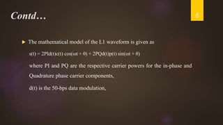
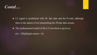
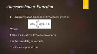
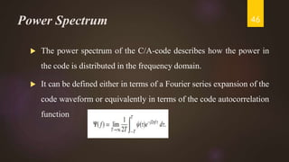
- The GPS signal consists of L1 and L2 carrier frequencies modulated by pseudorandom codes and data.
- The C/A code identifies individual satellites and supports signal acquisition. The P-code provides higher accuracy but is encrypted as Y-code for military use.
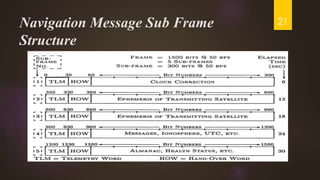
- Navigation data transmitted includes ephemeris, almanac, clock and ionospheric data used to determine satellite positions and timing corrections.


![GPS[Global Positioning System]](https://cdn.slidesharecdn.com/ss_thumbnails/globalpositioningsystem-130707095218-phpapp02-thumbnail.jpg?width=640&height=640&fit=bounds)