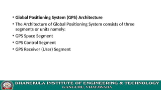
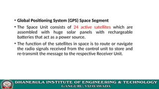
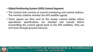
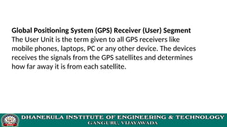
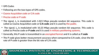
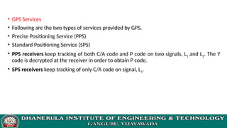
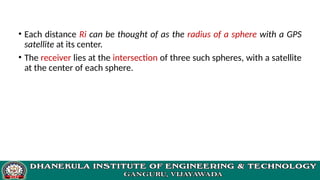
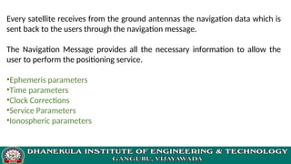
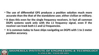
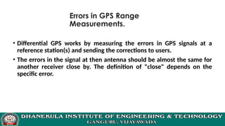
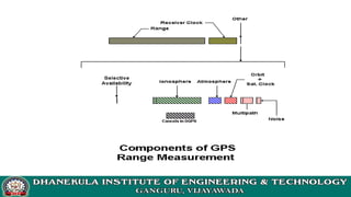
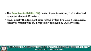
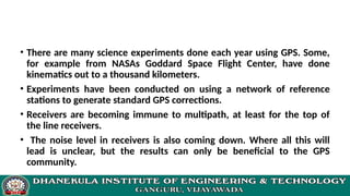
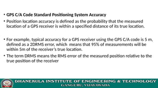
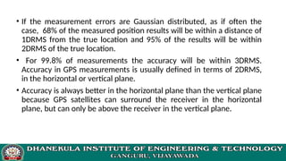
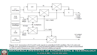
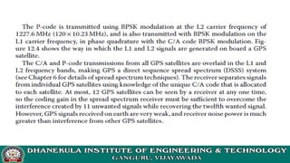
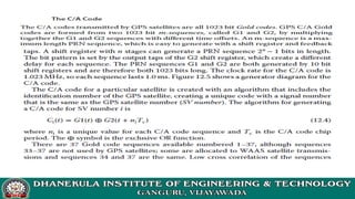
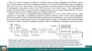
The document provides an overview of the Global Positioning System (GPS), detailing its architecture, components, and operational principles. It describes the roles of the GPS space segment, control segment, and receiver segment, as well as the various GPS codes and services. Additionally, it discusses the process of position determination using satellites and the significance of GPS time synchronization.
![UNIT V
• SATELLITE NAVIGATION & THE GLOBAL POSITIONING SYSTEM [1] :
Radio and Satellite Navigation, GPS Position Location principles,
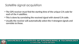
GPS Receivers and codes, Satellite signal acquisition,
GPS Navigation Message, GPS signal levels,
GPS receiver operation, GPS C/A code accuracy,
Differential GPS.](https://image.slidesharecdn.com/unit6gps-241209132354-8838725f/85/Unit-6-gps-ppt-presentation-on-gps-system-3-320.jpg)


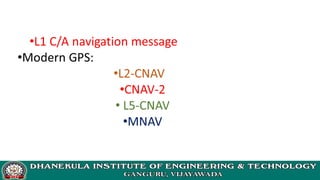
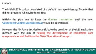
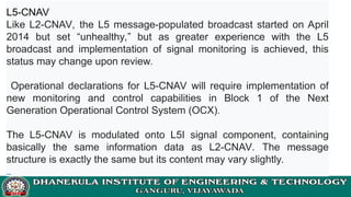
![On December 2014, the CNAV navigation message started to be updated on a
daily basis just like the legacy message but must be still considered as pre-
operational data and its use must be restricted to testing purposes[3]
.
Operational declarations for L2-CNAV will require implementation of new
monitoring and control capabilities in Block 1 of the Next Generation
Operational Control System (OCX).](https://image.slidesharecdn.com/unit6gps-241209132354-8838725f/85/Unit-6-gps-ppt-presentation-on-gps-system-52-320.jpg)


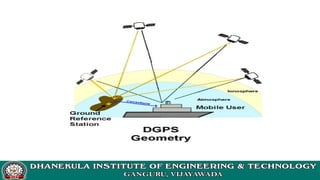


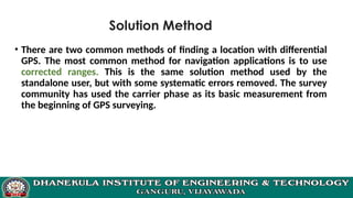
![• 7. b) Explain the principle and advantages of Differential GPS. [7]
• 7. a) Explain the generation of GPS L1 and L2 signals. [7]
• 7. a) Draw the basic architecture of GPS and explain in detail. [7]
• 7. a) Explain the various functions of Ground segment of GPS architecture. [7]
• b) Describe the format of GPS navigation message. [7]
• 7. a) Explain the position location principles of GPS system. [8]]
• 7. a) Explain about the GPS receivers and its codes. [8]](https://image.slidesharecdn.com/unit6gps-241209132354-8838725f/85/Unit-6-gps-ppt-presentation-on-gps-system-118-320.jpg)
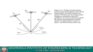
![• 7. a) Explain the trilateration method used for position of GPS receiver. [8]
• b) Explain the function of the non-coherent delay lock loop in GPS receiver.
[8]
• b) Explain the technology of range error budget used to provide accuracy in
GPS C/A code receiver.
• b) Write short note on GPS C/A code accuracy. [8]
• 7. a) Explain the functions of control segment in GPS. [8]
• b) Describe the various sources of errors in GPS. [8]
• 7. a) Write notes on GPS Navigation Message and GPS signal levels. [8]
• b) What are the different segments in GPS configuration? Explain. [8]](https://image.slidesharecdn.com/unit6gps-241209132354-8838725f/85/Unit-6-gps-ppt-presentation-on-gps-system-119-320.jpg)


![GPS[Global Positioning System]](https://cdn.slidesharecdn.com/ss_thumbnails/globalpositioningsystem-130707095218-phpapp02-thumbnail.jpg?width=640&height=640&fit=bounds)


