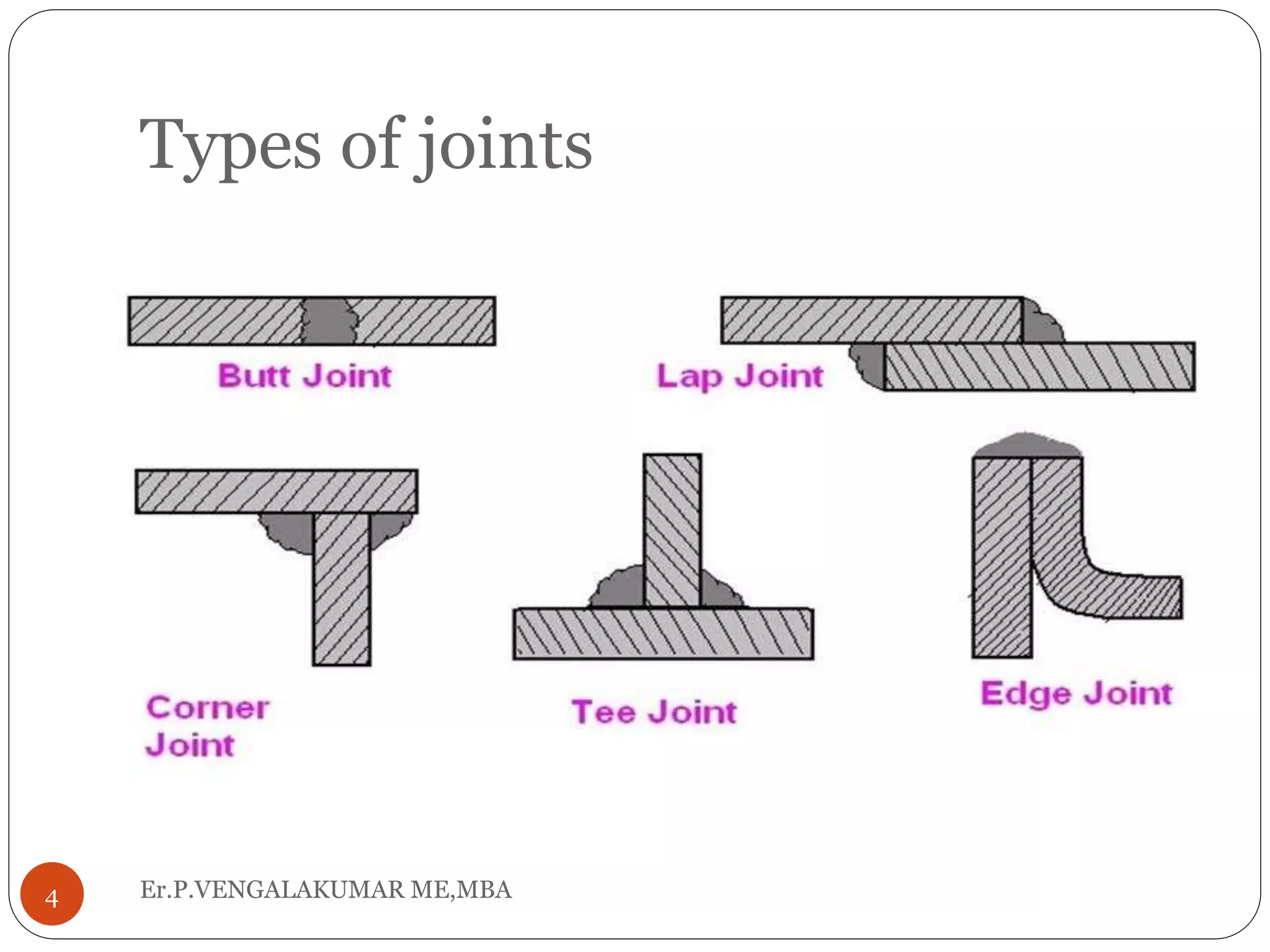
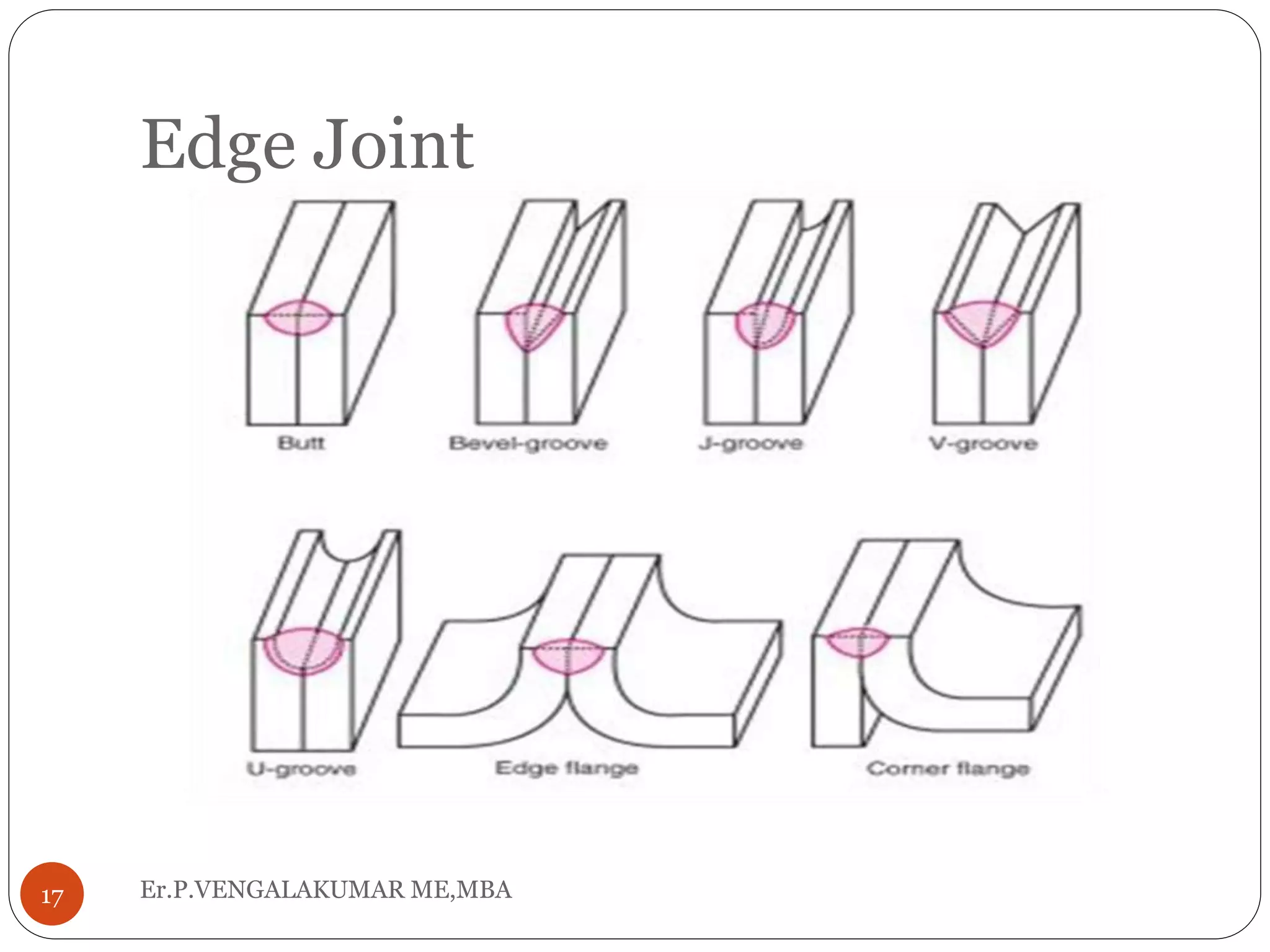
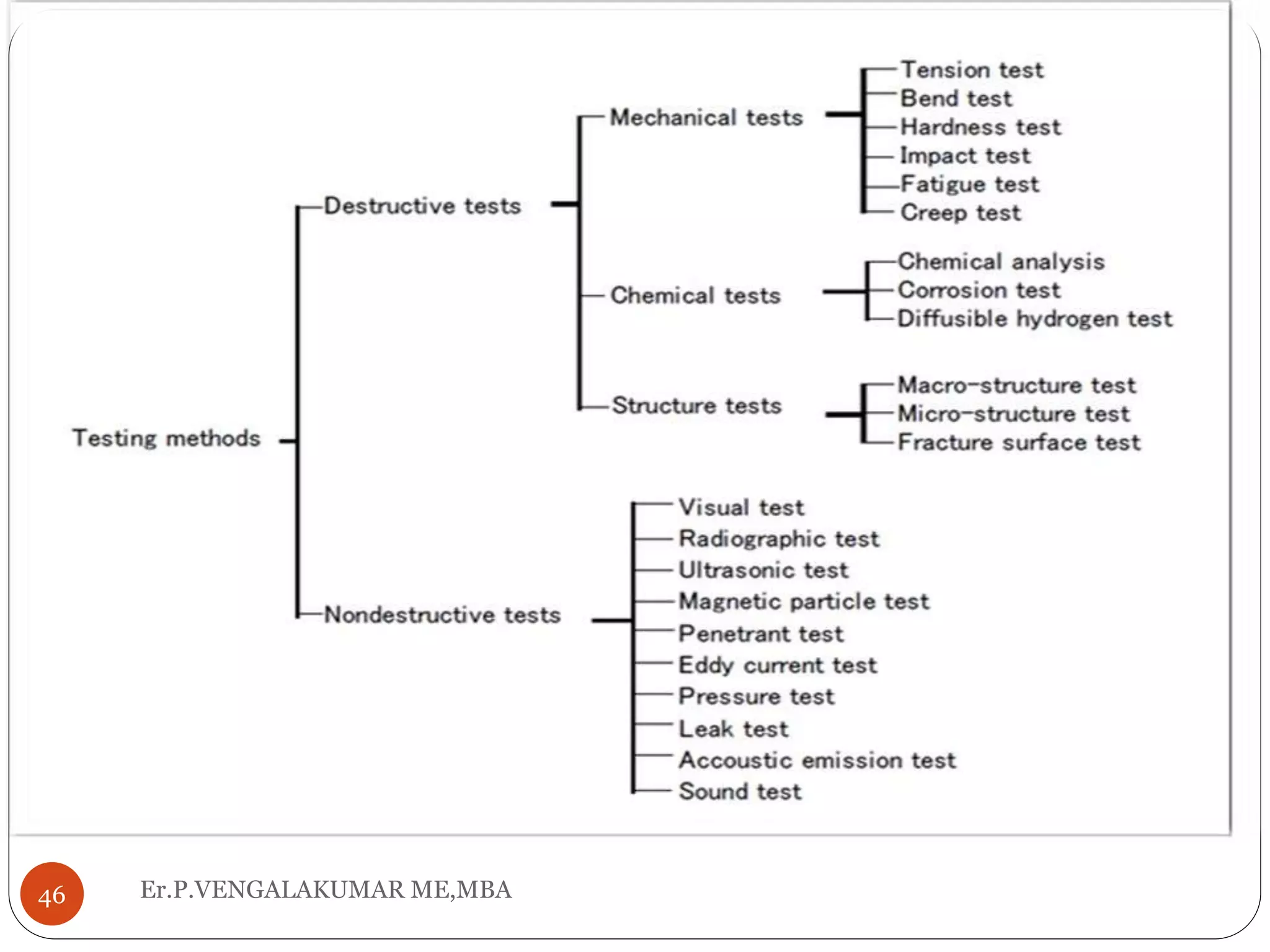
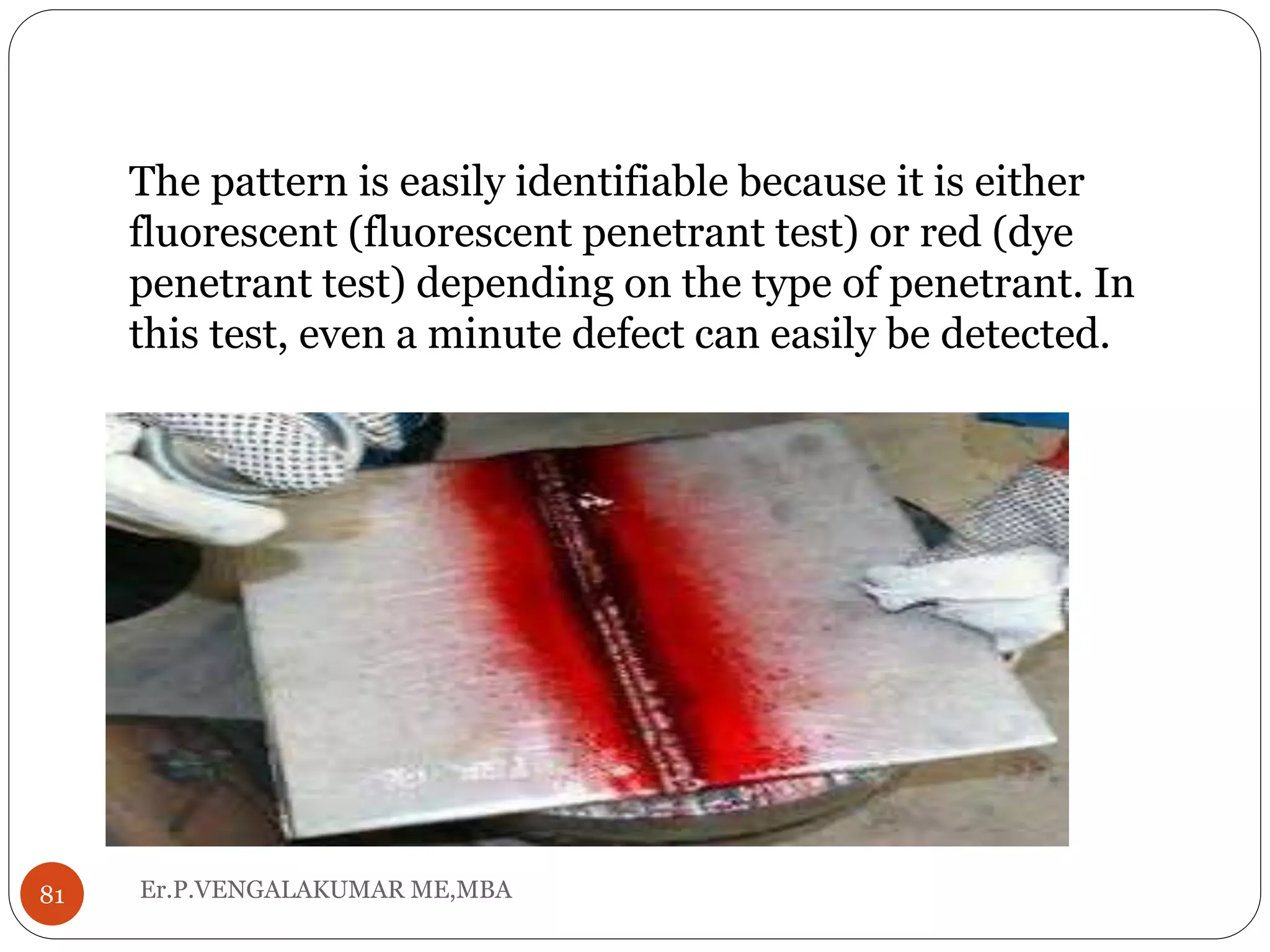
Er.P.VENGALAKUMAR ME,MBA1
PR 8592 WELDING TECHNOLOGY
UNIT-5
P.VENGALA KUMAR ME.,MBA
TF/MECHANICAL ENGG.,
UNIT -V DESIGN OF WELD JOINTS,
WELDABILITY AND TESTING OF
WELDMENTS
Er.P.VENGALAKUMAR ME,MBA2
 Various weld joint designs
 Welding defects
 Weldability of Aluminium,
 Weldability of Copper,
 Weldability of Stainless steels.
 Destructive and non destructive testing of
weldments.
welding joint
Er.P.VENGALAKUMAR ME,MBA3
 A welding joint is a point or edge where two or more
pieces of metal or plastic are joined together.
 They are formed by welding two or more workpieces
according to a particular geometry.
 There are five types of joints referred to by the
American Welding Society: butt, corner, edge, lap,
and tee
Types of joints
Er.P.VENGALAKUMAR ME,MBA4
TERMS IN WELDING JOINT
Er.P.VENGALAKUMAR ME,MBA5
Butt joint:
Er.P.VENGALAKUMAR ME,MBA6
 Butt joint is relatively easy to prepare and
perhaps the only joint that’s suitable for
automatic welding.
 Because there is a minimum obstruction on the
weld path, so the automated device (e.g. SAW)
can easily pass.
 This joint can be applied in any case, from plate to
pipe, from the simplest rig platform to the most
complex vessel wall.
Butt joint-(cont)
Er.P.VENGALAKUMAR ME,MBA7
 The drawback of this joint is minimum. There’s no
weld defect that’s exclusively caused by the use of
butt joint.
 It makes this joint a must use whenever possible.
 The most commonly occurring weld defects are
porosity, slag inclusion, incomplete penetration,
burn through, cracking, and incomplete fusion all of
which is independent of the joint design and can be
easily averted by manipulating the welding
variables
Butt joint:
Er.P.VENGALAKUMAR ME,MBA8
Tee joint
Er.P.VENGALAKUMAR ME,MBA9
 Tee joint is a joint on which the base metal is
perpendicularly configured to each other and
the welding is done as fillet weld on one side or
both side of the joint.
 Tee joint and any other fillet joints are not usually
prepared with groove unless the base metal is thick
and welding on both sides are not sufficient to
withstand the load imposed on the joint.
Tee joint(cont)
Er.P.VENGALAKUMAR ME,MBA10
 Though grooving is done like those of bevel, only
one of the base metal is chamfered.
 Tee joint found its application in many
components that are not possible to be weld
except perpendicularly.
 Tee joint can be welded with almost all welding
method with some complication found when
welded (though still possible) with SAW
(Submerged Arc Welding).
Tee joint(cont):
Er.P.VENGALAKUMAR ME,MBA11
Lap Joint
Er.P.VENGALAKUMAR ME,MBA12
 A modification of butt joint, where the material that
resides on the same plane is configured to overlap
each other and then fillet welded.
 However, there is also another welding method that
can be applied to lap joint such as slot weld, plug
weld, and spot weld.
 The application for this joint is mostly on sheet metal
while it’s also rarely used on thicker material such as
plates and pipe (socket weld).
 The base metal is not usually grooved when fillet
welded.
 Though in another welding method such as slot and
plug weld a special preparation is required to give
some kind of pathway for welding.
Lap joint
Er.P.VENGALAKUMAR ME,MBA13
Corner Joint
Er.P.VENGALAKUMAR ME,MBA14
 Corner joint is very similar to tee joint, the
difference is the location of the metal wherein tee
joint it’s positioned rather far from the corner or
simply said in the middle, but in corner joint the
corner of both metals meets in either closed or open
manner.
 It kind of looks like the corner of a box where the
two perpendicular metal meet.
 That being said, the application of this joint is
mostly on a metal box construction or any
construction that resembles a box.
 The joint can only be fillet welded with any welding
process that can reach the connection.
Corner Joint
Er.P.VENGALAKUMAR ME,MBA15
Edge Joint
Er.P.VENGALAKUMAR ME,MBA16
 This one is similar with lap joint where parts of the
base metal overlapping each other, but instead of
fillet welded this joint is butt welded on the
thickness side where the end of the material meets.
 This joint is also similar to flanged corner joint and
flanged butt joint, where part of the base metal is
bent and welded on the end side.
 Because there’s a contact area of the two metal,
corrosion is a problem.
 So does defects like porosity, slag inclusion, and
lack of fusion just like in any other type of joint.
Edge Joint
Er.P.VENGALAKUMAR ME,MBA17
Symbol of welding
Er.P.VENGALAKUMAR ME,MBA18
 Arrow points to the line or lines on drawing which
clearly identify the proposed joint or weld area.
 The tail of the welding symbol is used to
indicate the welding or cutting processes, as well
as the welding specification, procedures, or the
supplementary information to be used in making
the weld.
Er.P.VENGALAKUMAR ME,MBA19
Weldability
Er.P.VENGALAKUMAR ME,MBA20
 The weldability, also known as joinability of a
material refers to its ability to be welded.
Many metals and thermoplastics can be welded,
but some are easier to weld than others .
 A material's weld ability is used to determine the
welding process and to compare the final weld
quality to other materials.
THE WELDABILITY OF STAINLESS
STEEL
Er.P.VENGALAKUMAR ME,MBA21
 The Weldability Of Stainless Steel Known for its corrosion
resistance and wide range of uses in food handling,cutlery,and
many other applications,stainless steel is one of the most popular
metals in use today.
 The dozens of alloy variants make welding stainless steel more
complicated than welding traditional carbon steel.
 However, while stainless alloys were once considered a major
challenge to weld, today they are described as “different” as
opposed to “difficult” among most welders.
Er.P.VENGALAKUMAR ME,MBA22
 Stainless Steels are high alloy steels containing a
minimum of 10.5% chromium.
 Also they are usually alloyed with other elements
to improve heat resistance, mechanical
properties, and fabricating characteristics.
 These alloying elements also modify and
influence the weldability of stainless steel.
Er.P.VENGALAKUMAR ME,MBA23
 To successfully weld stainless, it is important to
know the various types of stainless and their
properties.
They are divided into five main types:
 ferritic,
 martensitic,
 precipitation hardening,
 duplex, and
 austeniti
PREPARING TO WELD
Er.P.VENGALAKUMAR ME,MBA24
 As in any type of welding, it is important to clean
stainless steel before welding it.
 What you may not realize is how sensitive the
stainless weld is to the presence of any carbon
steel.
 Make sure any tools you use to clean your
stainless are only used to clean stainless steel.
 For example, if you use a stainless steel brush to
clean carbon steel, don’t use it again on any
stainless steel.
 The same is true of stainless hammers and
clamps.
PREPARING TO WELD (CONT)
Er.P.VENGALAKUMAR ME,MBA25
 Trace amounts of carbon steel can transfer to the
stainless, causing it to rust.
 Similarly, grinding carbon steel in proximity to
stainless steel can result in problems.
 Carbon steel dust suspended in the air can land
on nearby stainless steel and lead to rusting.
 This is why it’s a good idea to keep carbon steel
and stainless steel work areas separate
PROCESSES
Er.P.VENGALAKUMAR ME,MBA26
 The procedure for welding stainless steel isn’t
vastly different from that of welding mild steel.
 Most all stainless steels can be joined through
various types of welding.
 In order to help you find the best one for your
material, here’s a breakdown of the ratings for the
weldability of stainless steel and other fabrication
properties for each type of stainless.
COMMON STAINLESS WELD
DEFECTS
Er.P.VENGALAKUMAR ME,MBA27
 Understanding common defects when welding is the
first step to preventing them.
 Welding stainless steel is not much different from
that required in welding standard carbon steel, with
a few exceptions.
 First, you must exercise more care and control with
regard to heating and cooling stainless steel.
 Second, it’s important to properly match filler
metals with the material being welded
Cracking
Er.P.VENGALAKUMAR ME,MBA28
 The most common welding imperfection for
stainless steels is cracking.
 Even with austenitic stainless steels, the most
readily welded of all stainless steels, has a risk of
cracking.
 This is because austenitic steels lack ferrite, which
dissolves harmful impurities that result in cracks.
In order to prevent cracking in these metals,
especially for fully austenitic structures, the
choice of a filler containing ferrite is highly
recommended.
stainless steel welding defects
Er.P.VENGALAKUMAR ME,MBA29
THE WELDABILITY OF
ALUMINUM
Er.P.VENGALAKUMAR ME,MBA30
 Aluminum and its alloys are popular metals
because of their low weight, good corrosion
resistance, and weldability.
 Although they typically possess low strength,
certain alloys can have mechanical properties
similar to steels.
 Aluminum alloys can be joined by a wide range of
methods.
Er.P.VENGALAKUMAR ME,MBA31
 But they also possess several properties that
require understanding depending on which
method you are using.
 Therefore, the first step to successful aluminum
welding is to familiarize yourself with the various
aluminum alloys, their properties, and the
considerations in choosing filler metal for each.
ALUMINUM ALLOYS
Er.P.VENGALAKUMAR ME,MBA32
 Pure aluminium is a relatively soft metal. But
when combined with alloying elements it can
produce a wide range of mechanical properties.
 These alloys are categorized into families
according to the principal alloying elements with
a four-digit identification system.
 Here is an overview of the of common families of
aluminum alloys and their weldability
characteristics along with common filler metals:
Non Heat-Treatable Aluminum
Alloys
Er.P.VENGALAKUMAR ME,MBA33
 For non-heat-treatable alloys, the material
strength of alloys depends on the effect of work
hardening and solid solution hardening of alloy
elements such as magnesium and manganese.
 These are mainly found in the 1000, 3000 and
5000 series aluminum alloys.
 When welded, these alloys may lose the effects of
work hardening and cause softening of the heat
affected zone adjacent to the weld.
Heat-Treatable Aluminum Alloys
Er.P.VENGALAKUMAR ME,MBA34
 The material hardness and strength of heat-
treatable alloys depend on their composition and
the heat treatment.
 The main alloying elements of these materials are
defined in the 2000, 6000 and 7000 series
aluminum alloys.
 Note that when fusion welding heat-treatable
alloys, the hardening constituents in the heat
affected zone (HAZ) is redistributed and results in
a reduction in material strength in the local area.
PROCESSES
Er.P.VENGALAKUMAR ME,MBA35
 TIG (Tungsten Inert Gas), MIG (Metal Inert Gas),
and oxyfuel processes are suitable processes for
fusion welding most of the wrought grades alloys in
particular have excellent weldabilty.
 These processes are also well suited for medium
strength 7 series alloys. We don’t recommend fusion
welding high strength alloys, such as 7010, 7050,
and a majority of the (2) alloys, because they are
prone to liquation and solidification.
 The Friction Stir Welding technique is particularly
suited for producing sound welds in aluminium
alloys. This technique is a good choice for heat-
treatable alloys which are prone to hot cracking.
COMMON ALUMINUM
WELDING DEFECTS
Er.P.VENGALAKUMAR ME,MBA36
 The weldability of Aluminium and its alloys is
good if you take appropriate precautions.
However,
 it is important to know the defects that may occur
and how to avoid them. The most common
defects in fusion welds
Porosity
Er.P.VENGALAKUMAR ME,MBA37
 Aluminum is one of the metals most susceptible
to porosity.
 Porosity is caused when hydrogen gas gets
trapped in the weld pool as the metal cools.
 Hydrogen becomes present from either water
vapor or hydrocarbon contamination through oils,
greases, lubricants, and solvents.
 While the weld metal is in the molten state, it
absorbs a high amount of hydrogen.
Porosity- (cont)
Er.P.VENGALAKUMAR ME,MBA38
 Then as it solidifies, it tries to expel the hydrogen.
However, if the weld is solidifying even moderately
quickly, the hydrogen doesn’t have a chance to
escape and instead stays behind and forms small
pores within the weld
Solidification Cracking
Er.P.VENGALAKUMAR ME,MBA39
 Because aluminum alloys experience high
thermal expansion and substantial contraction
upon solidification, they are also susceptible to
cracking.
 Typically these cracks occur along the center line
of the weld. It’s mainly caused due to an incorrect
filler and parent metal combination, incorrect
weld geometry, or when welding under high
restraint conditions.
 Furthermore, impurities like sulfur and
phosphorus are a major factor since these
elements separate during solidification.
Solidification Cracking -(cont)
Er.P.VENGALAKUMAR ME,MBA40
Therefore, it is important to remove the oil or
grease contamination from the weld area before
welding. Also, metals with a low melting point,
such as copper, tin, lead, and zinc, should also
be avoided.
Liquidation Cracking
Er.P.VENGALAKUMAR ME,MBA41
 Heat treatable alloys, particularly the 6XXX and
7XXX alloys, are more prone to liquaiton
cracking.
 This type of cracking results from localized
melting at grain boundaries of the heat affected
zone, combined with the inability to withstand the
contraction strains as the weld metal cools.
 But, the of risk liquation cracking can be reduced
by using a filler metal with a lower melting
temperature than the parent metal.
THE WELDABILITY OF COPPER
AND ITS ALLOYS
Er.P.VENGALAKUMAR ME,MBA42
 Copper and its alloys of Brass and Bronze are widely
used.
 Because of their excellent corrosion resistance and
ability to be strengthened, they are extremely versatile
and used in many different environments.
 Also, Copper possesses exceptional electrical and
thermal conductivity. Bronzes are mostly copper with
tin as main alloying element, while brass has zinc as
the alloying element. .
 But more recently chemists and metallurgists have
preferred to call this family of metals Copper and
Copper alloys instead of copper, brass, and bronze.
THE WELDABILITY OF COPPER
AND ITS ALLOYS- (CONT)
Er.P.VENGALAKUMAR ME,MBA43
 Although these terms are old and well known,
there is no distinct line between where one metal
ends and the other begins.
 When welding copper and its alloys, you want to
maintain the desirable corrosion resistance,
mechanical properties, and to avoid introducing
defects to the welds. Therefore, the first step to
success is familiarizing yourself with the various
alloys, their properties, and the considerations in
choosing filler metal for each.
THE WELDABILITY OF COPPER
AND ITS ALLOYS- (CONT)
Er.P.VENGALAKUMAR ME,MBA44
 Copper Alloys
 Brass Alloys
 Bronze Alloys
 Nickel Silver Alloys
COMMON COPPER ALLOY
WELDING DEFECTS
Er.P.VENGALAKUMAR ME,MBA45
 Porosity
 Lack of Fusion
 Hot Cracking
Er.P.VENGALAKUMAR ME,MBA46
DESTRUCTIVE TESTING
METHODS OF WELDED JOINTS
Er.P.VENGALAKUMAR ME,MBA47
 Three important destructive testing methods of
welded joints namely toughness test, fatigue test
and fracture toughness testing.
 Additionally, concept of fracture toughness and
conditions required for fracture toughness test for
different stress conditions has also been
presented.
 Further, non-destructive testing methods have
also been presented.
Er.P.VENGALAKUMAR ME,MBA48
 Keywords: Impact test, Izod and Charpy test,
fatigue test, endurance limit, fracture
toughness, plain strain condition, CT specimen,
three point bending specimen, Dye penetrant
test, magnetic particle test, eddy current test
and ultrasonic test
DESTRUCTIVE TESTING
49Er.P.VENGALAKUMAR ME,MBA
DESTRUCTIVE TESTING
Er.P.VENGALAKUMAR ME,MBA50
 TENSILE
 BENDING
 IMPACT
 HARDNES
 FATIGUE
 CRACKING
Tension test
Er.P.VENGALAKUMAR ME,MBA51
 Tension tests examine yield strength, tensile
strength, elongation and reduction in area by
stretching a tension test specimen until it
ruptures.
 The tension tests of a weld metal and a welded
joint are conducted according to the specification
to be followed for fillet welds, the shearing
strength of fillet joints is examined, using a
tension test machine.
Tensile test
Er.P.VENGALAKUMAR ME,MBA52
Bend test
Er.P.VENGALAKUMAR ME,MBA53
 Bend tests examine the ductility of welds and
whether they contain welding defects or not.
 Bend test specimens are usually removed from
butt weld joints so that the weld is perpendicular
to the longitudinal axis of the specimen.
Bend test (cont)
Er.P.VENGALAKUMAR ME,MBA54
 In bend tests, three different types of specimens
are used, depending on the surface to be tested:
 Face-bend specimens,
 Root-bend specimens, and
 Side-bend specimens.
 The bend tests include the roller bend test, guide
bend test, and free bend test.
Er.P.VENGALAKUMAR ME,MBA55
Impact test
Er.P.VENGALAKUMAR ME,MBA56
 Metals may be fractured in the ductile mode or
brittle mode depending on the environment
where the metals are loaded. The fracture of a
metal with plastic deformation in standard tensile
testing and slow bend testing is considered ductile
fracture.
 Ductile metals (as judged by tensile or bend
tests), however, may fracture with little or no
plastic deformation, when subjected to critical
testing or service conditions.
Impact test (cont)
Er.P.VENGALAKUMAR ME,MBA57
 This type of fracture is considered brittle fracture.
The critical conditions depend on the fracture
toughness of the metal. The brittle fracture is
considered more dangerous because a high-
velocity failure takes place in steel structures.
 Three factors markedly influence the brittle
fracture behavior of a metal; namely,
The presence of a notch in the metal,
 The temperature of the metal, and
The residual
Er.P.VENGALAKUMAR ME,MBA58
Hardness test
Er.P.VENGALAKUMAR ME,MBA59
 The hardness of a weld is the ability to resist
indentation or penetration by the point of a
material that is harder than the weld being tested.
 The hardness test is required to confirm whether
or not the weld is hard enough to resist
mechanical wearing, or whether or not the weld is
ductile enough to stresses, depending on the
usage of the weldment.
 Four different methods of measuring hardness
are in use depending upon the requirement:
Brinell, Rockwell, Vickers, and Shore hardness.
Er.P.VENGALAKUMAR ME,MBA60
 In particular, Vickers hardness is most suitable to
measure the hardness distribution in a weld.
Non- destructive tests
Er.P.VENGALAKUMAR ME,MBA61
 In order to guaranty the quality of a welded
structure, it is indispensable to know what
welding defects may or may not exist in the welds.
 For this purpose, a welded structure could be
examined by using a destructive test after
fabrication; however, the tested structure
becomes out of use if it is fractured by the test.
Non- destructive tests (cont)
Er.P.VENGALAKUMAR ME,MBA62
 Therefore, destructive tests are conducted with
test specimens, not with a product (except for the
sampling test for small products).
 Since finished products should never be fractured
by a test, it is important to examine the soundness
of the welds of the products without breaking
them. For this purpose, nondestructive tests are
conducted.
Visual test (VT)
Er.P.VENGALAKUMAR ME,MBA63
 A visual test is used to examine the appearance,
width and thickness of a weld and the welding
defects such as undercut, overlap, cracks, pits,
and slag inclusions in the surfaces of a weld. It is
also used to check whether the throat thickness is
as thick as specified and the misalignment is
within the allowance.
 This test is simple, inexpensive, and is capable of
examining many weld zones at one time.
Therefore, it is commonly applied to all welds.
Er.P.VENGALAKUMAR ME,MBA64
Radiographic test (RT)
Er.P.VENGALAKUMAR ME,MBA65
 When an accelerated electron hits a target of
heavy metal, the radiation emanates. This
radiation is a kind of electromagnetic wave. As its
wavelength is shorter, its penetrative capacity
becomes stronger. This penetrable capacity is
used in the X-ray test to detect defects inside
welds.
 Weld zones can also be examined utilizing the
radioactive isotopes (60Co; 192Ir, etc.) that emit γ
-rays. These two methods using X-rays and γ -
rays are called the radiographic test.
Er.P.VENGALAKUMAR ME,MBA66
 The extent of X-ray penetration varies depending
on the kind and thickness of the test material. The
radiation intensity changes at where there is a
welding defect, reflecting a change in
photosensitivity.
 The radiation intensity becomes denser at most
defects except for tungsten inclusions. Darker
portions in the negative film indicate the
existence of such defects as blowholes, lack of
fusion, lack of penetration, slag inclusions, cracks,
and undercut.
 .
Er.P.VENGALAKUMAR ME,MBA67
 A brighter spot in the negative film indicates a
tungsten inclusion, because tungsten absorbs the
radiation at a high degree. In taking
radiophotographs, an Image Quality Indicator
(I.Q.I.) and contrast meter are used in order to
confirm the quality of radiophotographs.
Magnetic particle test (MT)
Er.P.VENGALAKUMAR ME,MBA68
 Irons and ferritic steels can easily be magnetized by a
magnet.
 Therefore, if there is any defect on or near the
surfaces of a weldment, the magnetic poles will be
developed on both sides of the defect, producing the
leaked magnetic flux .
 When fine magnetic particles are brought near the
periphery of this magnetic flux, the particles are
magnetized, and the magnetic poles are developed at
both ends of each particle.
Magnetic particle test (MT) (cont)
Er.P.VENGALAKUMAR ME,MBA69
 The magnetic power acts through the magnetic
poles of the particles and defective zone.
Consequently, the particles are connected each
other to develop a particle pattern like a chain.
 For the magnetic particles, either a dry powder or
liquid suspension powder is used.
 By using this method, defects such as cracks and
porosity which are open to or close to the surface
of a weldment can be detected.
Magnetic Particle Inspection (Principle)
 Magnetic particle inspection is a non-destructive
testing method.
 which is used for detecting invisible cracks and
other defects in ferromagnetic materials such as
iron and steel.
 It is not applicable to nonmagnetic materials.
70 Er.P.VENGALAKUMAR ME,MBA
DIAGRAM: Magnetic Particle Inspection
71 Er.P.VENGALAKUMAR ME,MBA
WORKING: (Magnetic Particle Inspection)
 The inspection process consists of magnetizing the
part and then applying ferromagnetic particles to the
surface area are to be inspected.
 If a defect is present, the magnetic lines of force will
be disturbed and opposite poles will exist on either
side of the defect.
 The magnetized particles form a pattern in the
magnetic field between opposite poles.
 This pattern known as "indication" assumes the
approximate shape of the surface projection of the
defect
 In this experiment, commercially available magnetic
powder manufactured for NDT inspection will be
used.
72 Er.P.VENGALAKUMAR ME,MBA
Magnetic Particle Inspection (cont)
 A strong U shape magnet will be used to provide
the necessary magnetic field at the inspected area.
 This test is used to detect cracks, porosity and
inclusions in the welding.
 It is mainly used for testing ferromagnetic
materials (those that can be magnetized).
 Magnetic particle inspection can detect surface
and near surface defects
73 Er.P.VENGALAKUMAR ME,MBA
STEPS USED IN THE TESTING:
Magnetic Particle Inspection
 The surface of the specimen is roughly cleaned
wiping with a piece of textile
 The fluorescent magnetic spray is applied on the
surface being inspected
 Magnetic field is applied with a strong magnet to
the location of interest. The iron powder is
attracted to the crack and the iron powder will be
gathered near the cracks
 The spots where the fluorescent magnetic
particles accumulated is inspected under UV light
74 Er.P.VENGALAKUMAR ME,MBA
ADVANTAGES:Magnetic Particle
Inspection
 Large surface areas of complex parts can be
inspected rapidly.
 The test can detect surface and subsurface flaws.
 Surface preparation is less critical than it is in
penetrant inspection.
 Magnetic particle indications are produced directly
on the surface of the part and form an image of the
discontinuity.
 Equipment costs are relatively low
75 Er.P.VENGALAKUMAR ME,MBA
LIMITATION: Magnetic Particle Inspection
 Only ferromagnetic materials can be inspected.
 A proper alignment of magnetic field and defect is
critical.
 Large currents are needed for very large parts
 It requires relatively smooth surface.
 Paint or other nonmagnetic coverings adversely
affect sensitivity.
 Demagnetization and post cleaning are usually
necessary.
76 Er.P.VENGALAKUMAR ME,MBA
APPLICATION: Magnetic Particle Inspection
 Used for inspection of casting, forging, and
weldments on bridges, storage tanks, etc.
 Used by the structural steel, automotive,
petrochemical, power generation, and aerospace
industries.
 Even used for underwater inspection.
77 Er.P.VENGALAKUMAR ME,MBA
Ultrasonic test (UT)
Er.P.VENGALAKUMAR ME,MBA78
 In ultrasonic testing, beams of high frequency
sound waves or inaudible, short sonic waves of 0.5-
15 MHZ are introduced into a test object to detect
and locate surface and internal discontinuities.
 A sound beam is directed into the test object on a
predictable path, and is reflected at interfaces or
other interruptions in material continuity.
 The reflected beam is detected and analyzed to
define the presence and location of discontinuities.
Er.P.VENGALAKUMAR ME,MBA79
Penetrant test (PT)
Er.P.VENGALAKUMAR ME,MBA80
 The penetrant test uses fluorescent or red penetrant
to visualize defects such as cracks and pits that open
to the surface of a weld zone.
 If there is any defect that is open to the surface of a
weld, the applied penetrant penetrates into it.
 After it has fully penetrated the surface is cleaned
with water or solvent depending on the type of
penetrant.
 When a developing solution is applied, the penetrant
left in the defect comes to the surface exhibiting an
indication pattern.
Er.P.VENGALAKUMAR ME,MBA81
The pattern is easily identifiable because it is either
fluorescent (fluorescent penetrant test) or red (dye
penetrant test) depending on the type of penetrant. In
this test, even a minute defect can easily be detected.
Thank
you
Er.P.VENGALAKUMAR ME,MBA82

Unit 5 DESIGN OF WELD JOINTS, WELDABILITY AND TESTING OF WELDMENTS

  • 1.
    Er.P.VENGALAKUMAR ME,MBA1 PR 8592WELDING TECHNOLOGY UNIT-5 P.VENGALA KUMAR ME.,MBA TF/MECHANICAL ENGG.,
  • 2.
    UNIT -V DESIGNOF WELD JOINTS, WELDABILITY AND TESTING OF WELDMENTS Er.P.VENGALAKUMAR ME,MBA2  Various weld joint designs  Welding defects  Weldability of Aluminium,  Weldability of Copper,  Weldability of Stainless steels.  Destructive and non destructive testing of weldments.
  • 3.
    welding joint Er.P.VENGALAKUMAR ME,MBA3 A welding joint is a point or edge where two or more pieces of metal or plastic are joined together.  They are formed by welding two or more workpieces according to a particular geometry.  There are five types of joints referred to by the American Welding Society: butt, corner, edge, lap, and tee
  • 4.
  • 5.
    TERMS IN WELDINGJOINT Er.P.VENGALAKUMAR ME,MBA5
  • 6.
    Butt joint: Er.P.VENGALAKUMAR ME,MBA6 Butt joint is relatively easy to prepare and perhaps the only joint that’s suitable for automatic welding.  Because there is a minimum obstruction on the weld path, so the automated device (e.g. SAW) can easily pass.  This joint can be applied in any case, from plate to pipe, from the simplest rig platform to the most complex vessel wall.
  • 7.
    Butt joint-(cont) Er.P.VENGALAKUMAR ME,MBA7 The drawback of this joint is minimum. There’s no weld defect that’s exclusively caused by the use of butt joint.  It makes this joint a must use whenever possible.  The most commonly occurring weld defects are porosity, slag inclusion, incomplete penetration, burn through, cracking, and incomplete fusion all of which is independent of the joint design and can be easily averted by manipulating the welding variables
  • 8.
  • 9.
    Tee joint Er.P.VENGALAKUMAR ME,MBA9 Tee joint is a joint on which the base metal is perpendicularly configured to each other and the welding is done as fillet weld on one side or both side of the joint.  Tee joint and any other fillet joints are not usually prepared with groove unless the base metal is thick and welding on both sides are not sufficient to withstand the load imposed on the joint.
  • 10.
    Tee joint(cont) Er.P.VENGALAKUMAR ME,MBA10 Though grooving is done like those of bevel, only one of the base metal is chamfered.  Tee joint found its application in many components that are not possible to be weld except perpendicularly.  Tee joint can be welded with almost all welding method with some complication found when welded (though still possible) with SAW (Submerged Arc Welding).
  • 11.
  • 12.
    Lap Joint Er.P.VENGALAKUMAR ME,MBA12 A modification of butt joint, where the material that resides on the same plane is configured to overlap each other and then fillet welded.  However, there is also another welding method that can be applied to lap joint such as slot weld, plug weld, and spot weld.  The application for this joint is mostly on sheet metal while it’s also rarely used on thicker material such as plates and pipe (socket weld).  The base metal is not usually grooved when fillet welded.  Though in another welding method such as slot and plug weld a special preparation is required to give some kind of pathway for welding.
  • 13.
  • 14.
    Corner Joint Er.P.VENGALAKUMAR ME,MBA14 Corner joint is very similar to tee joint, the difference is the location of the metal wherein tee joint it’s positioned rather far from the corner or simply said in the middle, but in corner joint the corner of both metals meets in either closed or open manner.  It kind of looks like the corner of a box where the two perpendicular metal meet.  That being said, the application of this joint is mostly on a metal box construction or any construction that resembles a box.  The joint can only be fillet welded with any welding process that can reach the connection.
  • 15.
  • 16.
    Edge Joint Er.P.VENGALAKUMAR ME,MBA16 This one is similar with lap joint where parts of the base metal overlapping each other, but instead of fillet welded this joint is butt welded on the thickness side where the end of the material meets.  This joint is also similar to flanged corner joint and flanged butt joint, where part of the base metal is bent and welded on the end side.  Because there’s a contact area of the two metal, corrosion is a problem.  So does defects like porosity, slag inclusion, and lack of fusion just like in any other type of joint.
  • 17.
  • 18.
    Symbol of welding Er.P.VENGALAKUMARME,MBA18  Arrow points to the line or lines on drawing which clearly identify the proposed joint or weld area.  The tail of the welding symbol is used to indicate the welding or cutting processes, as well as the welding specification, procedures, or the supplementary information to be used in making the weld.
  • 19.
  • 20.
    Weldability Er.P.VENGALAKUMAR ME,MBA20  Theweldability, also known as joinability of a material refers to its ability to be welded. Many metals and thermoplastics can be welded, but some are easier to weld than others .  A material's weld ability is used to determine the welding process and to compare the final weld quality to other materials.
  • 21.
    THE WELDABILITY OFSTAINLESS STEEL Er.P.VENGALAKUMAR ME,MBA21  The Weldability Of Stainless Steel Known for its corrosion resistance and wide range of uses in food handling,cutlery,and many other applications,stainless steel is one of the most popular metals in use today.  The dozens of alloy variants make welding stainless steel more complicated than welding traditional carbon steel.  However, while stainless alloys were once considered a major challenge to weld, today they are described as “different” as opposed to “difficult” among most welders.
  • 22.
    Er.P.VENGALAKUMAR ME,MBA22  StainlessSteels are high alloy steels containing a minimum of 10.5% chromium.  Also they are usually alloyed with other elements to improve heat resistance, mechanical properties, and fabricating characteristics.  These alloying elements also modify and influence the weldability of stainless steel.
  • 23.
    Er.P.VENGALAKUMAR ME,MBA23  Tosuccessfully weld stainless, it is important to know the various types of stainless and their properties. They are divided into five main types:  ferritic,  martensitic,  precipitation hardening,  duplex, and  austeniti
  • 24.
    PREPARING TO WELD Er.P.VENGALAKUMARME,MBA24  As in any type of welding, it is important to clean stainless steel before welding it.  What you may not realize is how sensitive the stainless weld is to the presence of any carbon steel.  Make sure any tools you use to clean your stainless are only used to clean stainless steel.  For example, if you use a stainless steel brush to clean carbon steel, don’t use it again on any stainless steel.  The same is true of stainless hammers and clamps.
  • 25.
    PREPARING TO WELD(CONT) Er.P.VENGALAKUMAR ME,MBA25  Trace amounts of carbon steel can transfer to the stainless, causing it to rust.  Similarly, grinding carbon steel in proximity to stainless steel can result in problems.  Carbon steel dust suspended in the air can land on nearby stainless steel and lead to rusting.  This is why it’s a good idea to keep carbon steel and stainless steel work areas separate
  • 26.
    PROCESSES Er.P.VENGALAKUMAR ME,MBA26  Theprocedure for welding stainless steel isn’t vastly different from that of welding mild steel.  Most all stainless steels can be joined through various types of welding.  In order to help you find the best one for your material, here’s a breakdown of the ratings for the weldability of stainless steel and other fabrication properties for each type of stainless.
  • 27.
    COMMON STAINLESS WELD DEFECTS Er.P.VENGALAKUMARME,MBA27  Understanding common defects when welding is the first step to preventing them.  Welding stainless steel is not much different from that required in welding standard carbon steel, with a few exceptions.  First, you must exercise more care and control with regard to heating and cooling stainless steel.  Second, it’s important to properly match filler metals with the material being welded
  • 28.
    Cracking Er.P.VENGALAKUMAR ME,MBA28  Themost common welding imperfection for stainless steels is cracking.  Even with austenitic stainless steels, the most readily welded of all stainless steels, has a risk of cracking.  This is because austenitic steels lack ferrite, which dissolves harmful impurities that result in cracks. In order to prevent cracking in these metals, especially for fully austenitic structures, the choice of a filler containing ferrite is highly recommended.
  • 29.
    stainless steel weldingdefects Er.P.VENGALAKUMAR ME,MBA29
  • 30.
    THE WELDABILITY OF ALUMINUM Er.P.VENGALAKUMARME,MBA30  Aluminum and its alloys are popular metals because of their low weight, good corrosion resistance, and weldability.  Although they typically possess low strength, certain alloys can have mechanical properties similar to steels.  Aluminum alloys can be joined by a wide range of methods.
  • 31.
    Er.P.VENGALAKUMAR ME,MBA31  Butthey also possess several properties that require understanding depending on which method you are using.  Therefore, the first step to successful aluminum welding is to familiarize yourself with the various aluminum alloys, their properties, and the considerations in choosing filler metal for each.
  • 32.
    ALUMINUM ALLOYS Er.P.VENGALAKUMAR ME,MBA32 Pure aluminium is a relatively soft metal. But when combined with alloying elements it can produce a wide range of mechanical properties.  These alloys are categorized into families according to the principal alloying elements with a four-digit identification system.  Here is an overview of the of common families of aluminum alloys and their weldability characteristics along with common filler metals:
  • 33.
    Non Heat-Treatable Aluminum Alloys Er.P.VENGALAKUMARME,MBA33  For non-heat-treatable alloys, the material strength of alloys depends on the effect of work hardening and solid solution hardening of alloy elements such as magnesium and manganese.  These are mainly found in the 1000, 3000 and 5000 series aluminum alloys.  When welded, these alloys may lose the effects of work hardening and cause softening of the heat affected zone adjacent to the weld.
  • 34.
    Heat-Treatable Aluminum Alloys Er.P.VENGALAKUMARME,MBA34  The material hardness and strength of heat- treatable alloys depend on their composition and the heat treatment.  The main alloying elements of these materials are defined in the 2000, 6000 and 7000 series aluminum alloys.  Note that when fusion welding heat-treatable alloys, the hardening constituents in the heat affected zone (HAZ) is redistributed and results in a reduction in material strength in the local area.
  • 35.
    PROCESSES Er.P.VENGALAKUMAR ME,MBA35  TIG(Tungsten Inert Gas), MIG (Metal Inert Gas), and oxyfuel processes are suitable processes for fusion welding most of the wrought grades alloys in particular have excellent weldabilty.  These processes are also well suited for medium strength 7 series alloys. We don’t recommend fusion welding high strength alloys, such as 7010, 7050, and a majority of the (2) alloys, because they are prone to liquation and solidification.  The Friction Stir Welding technique is particularly suited for producing sound welds in aluminium alloys. This technique is a good choice for heat- treatable alloys which are prone to hot cracking.
  • 36.
    COMMON ALUMINUM WELDING DEFECTS Er.P.VENGALAKUMARME,MBA36  The weldability of Aluminium and its alloys is good if you take appropriate precautions. However,  it is important to know the defects that may occur and how to avoid them. The most common defects in fusion welds
  • 37.
    Porosity Er.P.VENGALAKUMAR ME,MBA37  Aluminumis one of the metals most susceptible to porosity.  Porosity is caused when hydrogen gas gets trapped in the weld pool as the metal cools.  Hydrogen becomes present from either water vapor or hydrocarbon contamination through oils, greases, lubricants, and solvents.  While the weld metal is in the molten state, it absorbs a high amount of hydrogen.
  • 38.
    Porosity- (cont) Er.P.VENGALAKUMAR ME,MBA38 Then as it solidifies, it tries to expel the hydrogen. However, if the weld is solidifying even moderately quickly, the hydrogen doesn’t have a chance to escape and instead stays behind and forms small pores within the weld
  • 39.
    Solidification Cracking Er.P.VENGALAKUMAR ME,MBA39 Because aluminum alloys experience high thermal expansion and substantial contraction upon solidification, they are also susceptible to cracking.  Typically these cracks occur along the center line of the weld. It’s mainly caused due to an incorrect filler and parent metal combination, incorrect weld geometry, or when welding under high restraint conditions.  Furthermore, impurities like sulfur and phosphorus are a major factor since these elements separate during solidification.
  • 40.
    Solidification Cracking -(cont) Er.P.VENGALAKUMARME,MBA40 Therefore, it is important to remove the oil or grease contamination from the weld area before welding. Also, metals with a low melting point, such as copper, tin, lead, and zinc, should also be avoided.
  • 41.
    Liquidation Cracking Er.P.VENGALAKUMAR ME,MBA41 Heat treatable alloys, particularly the 6XXX and 7XXX alloys, are more prone to liquaiton cracking.  This type of cracking results from localized melting at grain boundaries of the heat affected zone, combined with the inability to withstand the contraction strains as the weld metal cools.  But, the of risk liquation cracking can be reduced by using a filler metal with a lower melting temperature than the parent metal.
  • 42.
    THE WELDABILITY OFCOPPER AND ITS ALLOYS Er.P.VENGALAKUMAR ME,MBA42  Copper and its alloys of Brass and Bronze are widely used.  Because of their excellent corrosion resistance and ability to be strengthened, they are extremely versatile and used in many different environments.  Also, Copper possesses exceptional electrical and thermal conductivity. Bronzes are mostly copper with tin as main alloying element, while brass has zinc as the alloying element. .  But more recently chemists and metallurgists have preferred to call this family of metals Copper and Copper alloys instead of copper, brass, and bronze.
  • 43.
    THE WELDABILITY OFCOPPER AND ITS ALLOYS- (CONT) Er.P.VENGALAKUMAR ME,MBA43  Although these terms are old and well known, there is no distinct line between where one metal ends and the other begins.  When welding copper and its alloys, you want to maintain the desirable corrosion resistance, mechanical properties, and to avoid introducing defects to the welds. Therefore, the first step to success is familiarizing yourself with the various alloys, their properties, and the considerations in choosing filler metal for each.
  • 44.
    THE WELDABILITY OFCOPPER AND ITS ALLOYS- (CONT) Er.P.VENGALAKUMAR ME,MBA44  Copper Alloys  Brass Alloys  Bronze Alloys  Nickel Silver Alloys
  • 45.
    COMMON COPPER ALLOY WELDINGDEFECTS Er.P.VENGALAKUMAR ME,MBA45  Porosity  Lack of Fusion  Hot Cracking
  • 46.
  • 47.
    DESTRUCTIVE TESTING METHODS OFWELDED JOINTS Er.P.VENGALAKUMAR ME,MBA47  Three important destructive testing methods of welded joints namely toughness test, fatigue test and fracture toughness testing.  Additionally, concept of fracture toughness and conditions required for fracture toughness test for different stress conditions has also been presented.  Further, non-destructive testing methods have also been presented.
  • 48.
    Er.P.VENGALAKUMAR ME,MBA48  Keywords:Impact test, Izod and Charpy test, fatigue test, endurance limit, fracture toughness, plain strain condition, CT specimen, three point bending specimen, Dye penetrant test, magnetic particle test, eddy current test and ultrasonic test
  • 49.
  • 50.
    DESTRUCTIVE TESTING Er.P.VENGALAKUMAR ME,MBA50 TENSILE  BENDING  IMPACT  HARDNES  FATIGUE  CRACKING
  • 51.
    Tension test Er.P.VENGALAKUMAR ME,MBA51 Tension tests examine yield strength, tensile strength, elongation and reduction in area by stretching a tension test specimen until it ruptures.  The tension tests of a weld metal and a welded joint are conducted according to the specification to be followed for fillet welds, the shearing strength of fillet joints is examined, using a tension test machine.
  • 52.
  • 53.
    Bend test Er.P.VENGALAKUMAR ME,MBA53 Bend tests examine the ductility of welds and whether they contain welding defects or not.  Bend test specimens are usually removed from butt weld joints so that the weld is perpendicular to the longitudinal axis of the specimen.
  • 54.
    Bend test (cont) Er.P.VENGALAKUMARME,MBA54  In bend tests, three different types of specimens are used, depending on the surface to be tested:  Face-bend specimens,  Root-bend specimens, and  Side-bend specimens.  The bend tests include the roller bend test, guide bend test, and free bend test.
  • 55.
  • 56.
    Impact test Er.P.VENGALAKUMAR ME,MBA56 Metals may be fractured in the ductile mode or brittle mode depending on the environment where the metals are loaded. The fracture of a metal with plastic deformation in standard tensile testing and slow bend testing is considered ductile fracture.  Ductile metals (as judged by tensile or bend tests), however, may fracture with little or no plastic deformation, when subjected to critical testing or service conditions.
  • 57.
    Impact test (cont) Er.P.VENGALAKUMARME,MBA57  This type of fracture is considered brittle fracture. The critical conditions depend on the fracture toughness of the metal. The brittle fracture is considered more dangerous because a high- velocity failure takes place in steel structures.  Three factors markedly influence the brittle fracture behavior of a metal; namely, The presence of a notch in the metal,  The temperature of the metal, and The residual
  • 58.
  • 59.
    Hardness test Er.P.VENGALAKUMAR ME,MBA59 The hardness of a weld is the ability to resist indentation or penetration by the point of a material that is harder than the weld being tested.  The hardness test is required to confirm whether or not the weld is hard enough to resist mechanical wearing, or whether or not the weld is ductile enough to stresses, depending on the usage of the weldment.  Four different methods of measuring hardness are in use depending upon the requirement: Brinell, Rockwell, Vickers, and Shore hardness.
  • 60.
    Er.P.VENGALAKUMAR ME,MBA60  Inparticular, Vickers hardness is most suitable to measure the hardness distribution in a weld.
  • 61.
    Non- destructive tests Er.P.VENGALAKUMARME,MBA61  In order to guaranty the quality of a welded structure, it is indispensable to know what welding defects may or may not exist in the welds.  For this purpose, a welded structure could be examined by using a destructive test after fabrication; however, the tested structure becomes out of use if it is fractured by the test.
  • 62.
    Non- destructive tests(cont) Er.P.VENGALAKUMAR ME,MBA62  Therefore, destructive tests are conducted with test specimens, not with a product (except for the sampling test for small products).  Since finished products should never be fractured by a test, it is important to examine the soundness of the welds of the products without breaking them. For this purpose, nondestructive tests are conducted.
  • 63.
    Visual test (VT) Er.P.VENGALAKUMARME,MBA63  A visual test is used to examine the appearance, width and thickness of a weld and the welding defects such as undercut, overlap, cracks, pits, and slag inclusions in the surfaces of a weld. It is also used to check whether the throat thickness is as thick as specified and the misalignment is within the allowance.  This test is simple, inexpensive, and is capable of examining many weld zones at one time. Therefore, it is commonly applied to all welds.
  • 64.
  • 65.
    Radiographic test (RT) Er.P.VENGALAKUMARME,MBA65  When an accelerated electron hits a target of heavy metal, the radiation emanates. This radiation is a kind of electromagnetic wave. As its wavelength is shorter, its penetrative capacity becomes stronger. This penetrable capacity is used in the X-ray test to detect defects inside welds.  Weld zones can also be examined utilizing the radioactive isotopes (60Co; 192Ir, etc.) that emit γ -rays. These two methods using X-rays and γ - rays are called the radiographic test.
  • 66.
    Er.P.VENGALAKUMAR ME,MBA66  Theextent of X-ray penetration varies depending on the kind and thickness of the test material. The radiation intensity changes at where there is a welding defect, reflecting a change in photosensitivity.  The radiation intensity becomes denser at most defects except for tungsten inclusions. Darker portions in the negative film indicate the existence of such defects as blowholes, lack of fusion, lack of penetration, slag inclusions, cracks, and undercut.  .
  • 67.
    Er.P.VENGALAKUMAR ME,MBA67  Abrighter spot in the negative film indicates a tungsten inclusion, because tungsten absorbs the radiation at a high degree. In taking radiophotographs, an Image Quality Indicator (I.Q.I.) and contrast meter are used in order to confirm the quality of radiophotographs.
  • 68.
    Magnetic particle test(MT) Er.P.VENGALAKUMAR ME,MBA68  Irons and ferritic steels can easily be magnetized by a magnet.  Therefore, if there is any defect on or near the surfaces of a weldment, the magnetic poles will be developed on both sides of the defect, producing the leaked magnetic flux .  When fine magnetic particles are brought near the periphery of this magnetic flux, the particles are magnetized, and the magnetic poles are developed at both ends of each particle.
  • 69.
    Magnetic particle test(MT) (cont) Er.P.VENGALAKUMAR ME,MBA69  The magnetic power acts through the magnetic poles of the particles and defective zone. Consequently, the particles are connected each other to develop a particle pattern like a chain.  For the magnetic particles, either a dry powder or liquid suspension powder is used.  By using this method, defects such as cracks and porosity which are open to or close to the surface of a weldment can be detected.
  • 70.
    Magnetic Particle Inspection(Principle)  Magnetic particle inspection is a non-destructive testing method.  which is used for detecting invisible cracks and other defects in ferromagnetic materials such as iron and steel.  It is not applicable to nonmagnetic materials. 70 Er.P.VENGALAKUMAR ME,MBA
  • 71.
    DIAGRAM: Magnetic ParticleInspection 71 Er.P.VENGALAKUMAR ME,MBA
  • 72.
    WORKING: (Magnetic ParticleInspection)  The inspection process consists of magnetizing the part and then applying ferromagnetic particles to the surface area are to be inspected.  If a defect is present, the magnetic lines of force will be disturbed and opposite poles will exist on either side of the defect.  The magnetized particles form a pattern in the magnetic field between opposite poles.  This pattern known as "indication" assumes the approximate shape of the surface projection of the defect  In this experiment, commercially available magnetic powder manufactured for NDT inspection will be used. 72 Er.P.VENGALAKUMAR ME,MBA
  • 73.
    Magnetic Particle Inspection(cont)  A strong U shape magnet will be used to provide the necessary magnetic field at the inspected area.  This test is used to detect cracks, porosity and inclusions in the welding.  It is mainly used for testing ferromagnetic materials (those that can be magnetized).  Magnetic particle inspection can detect surface and near surface defects 73 Er.P.VENGALAKUMAR ME,MBA
  • 74.
    STEPS USED INTHE TESTING: Magnetic Particle Inspection  The surface of the specimen is roughly cleaned wiping with a piece of textile  The fluorescent magnetic spray is applied on the surface being inspected  Magnetic field is applied with a strong magnet to the location of interest. The iron powder is attracted to the crack and the iron powder will be gathered near the cracks  The spots where the fluorescent magnetic particles accumulated is inspected under UV light 74 Er.P.VENGALAKUMAR ME,MBA
  • 75.
    ADVANTAGES:Magnetic Particle Inspection  Largesurface areas of complex parts can be inspected rapidly.  The test can detect surface and subsurface flaws.  Surface preparation is less critical than it is in penetrant inspection.  Magnetic particle indications are produced directly on the surface of the part and form an image of the discontinuity.  Equipment costs are relatively low 75 Er.P.VENGALAKUMAR ME,MBA
  • 76.
    LIMITATION: Magnetic ParticleInspection  Only ferromagnetic materials can be inspected.  A proper alignment of magnetic field and defect is critical.  Large currents are needed for very large parts  It requires relatively smooth surface.  Paint or other nonmagnetic coverings adversely affect sensitivity.  Demagnetization and post cleaning are usually necessary. 76 Er.P.VENGALAKUMAR ME,MBA
  • 77.
    APPLICATION: Magnetic ParticleInspection  Used for inspection of casting, forging, and weldments on bridges, storage tanks, etc.  Used by the structural steel, automotive, petrochemical, power generation, and aerospace industries.  Even used for underwater inspection. 77 Er.P.VENGALAKUMAR ME,MBA
  • 78.
    Ultrasonic test (UT) Er.P.VENGALAKUMARME,MBA78  In ultrasonic testing, beams of high frequency sound waves or inaudible, short sonic waves of 0.5- 15 MHZ are introduced into a test object to detect and locate surface and internal discontinuities.  A sound beam is directed into the test object on a predictable path, and is reflected at interfaces or other interruptions in material continuity.  The reflected beam is detected and analyzed to define the presence and location of discontinuities.
  • 79.
  • 80.
    Penetrant test (PT) Er.P.VENGALAKUMARME,MBA80  The penetrant test uses fluorescent or red penetrant to visualize defects such as cracks and pits that open to the surface of a weld zone.  If there is any defect that is open to the surface of a weld, the applied penetrant penetrates into it.  After it has fully penetrated the surface is cleaned with water or solvent depending on the type of penetrant.  When a developing solution is applied, the penetrant left in the defect comes to the surface exhibiting an indication pattern.
  • 81.
    Er.P.VENGALAKUMAR ME,MBA81 The patternis easily identifiable because it is either fluorescent (fluorescent penetrant test) or red (dye penetrant test) depending on the type of penetrant. In this test, even a minute defect can easily be detected.
  • 82.