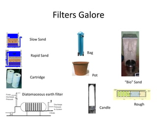
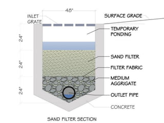
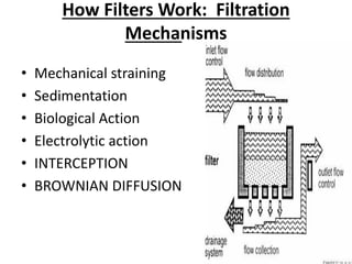
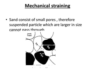
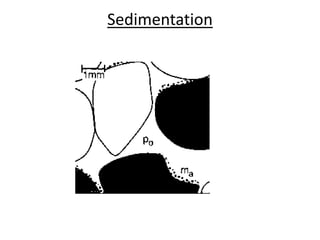
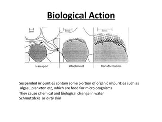
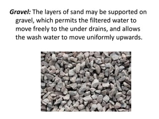
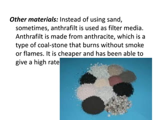
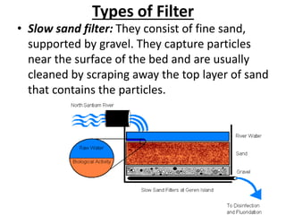
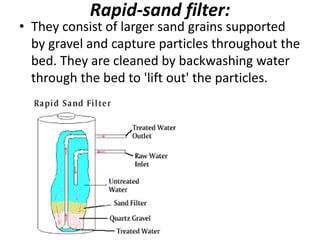
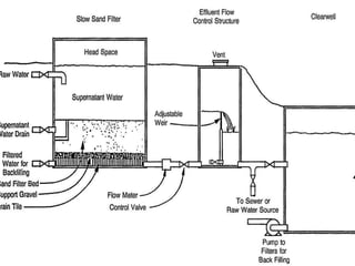
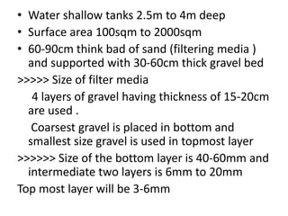
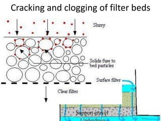
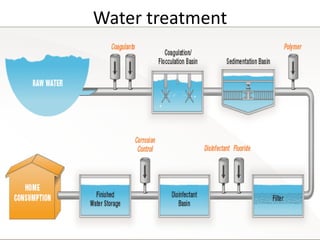
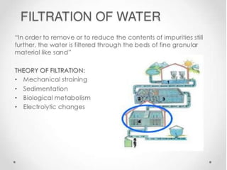
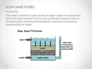
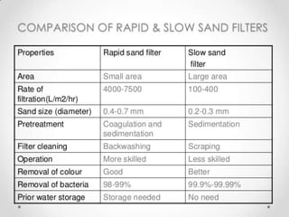
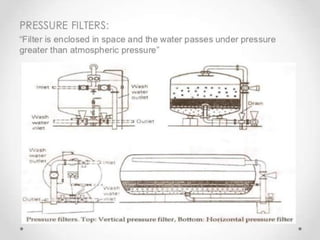
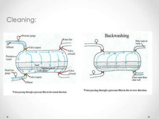
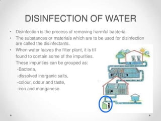
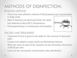
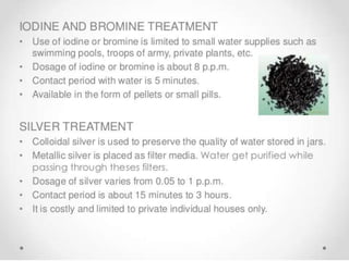
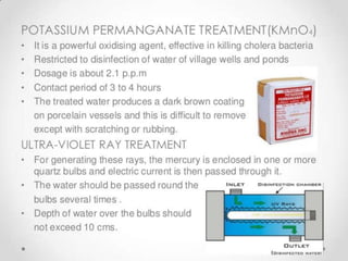
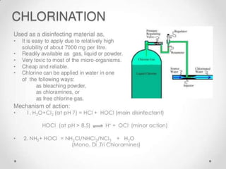
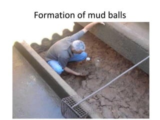
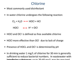
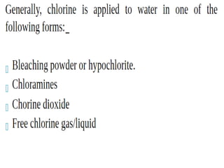
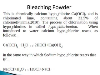
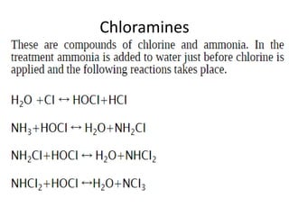
Filtration
Filters Galore
“Bio” Sand
Rapid Sand
Cartridge
Bag
Pot
Candle
Diatomaceous earth filter
Slow Sand
Rough
Filtration
• The resultant water after sedimentation will
not be pure, and may contain some very fine
suspended particles and bacteria in it. To
remove or to reduce the remaining impurities
still further, the water is filtered through the
beds of fine granular material, such as sand,
etc. The process of passing the water through
the beds of such granular materials is known
as Filtration
How Filters Work: Filtration
Mechanisms
• Mechanical straining
• Sedimentation
• Biological Action
• Electrolytic action
• INTERCEPTION
• BROWNIAN DIFFUSION
Mechanical straining
• Sand consist of small pores , therefore
suspended particle which are larger in size
cannot pass through
Sedimentation
Biological Action
Suspended impurities contain some portion of organic impurities such as
algae , plankton etc, which are food for micro oragnisms
They cause chemical and biological change in water
Schmutzdcke or dirty skin
Electrolytic action
• The sand particles of filter media and ionized
matter in water carry electrical charge of
opposite nature , therefore they attract each
other and neutralize the charge of each other
INTERCEPTION :
Interception of particles is common for large
particles. If a large enough particle follows the
streamline, that lies very close to the media
surface it will hit the media grain and be
captured.
BROWNIAN DIFFUSION
• Diffusion towards media granules occurs for
very small particles, such as viruses. Particles
move randomly about within the fluid, due to
thermal gradients. This mechanism is only
important for particles with diameters < 1
micron.
Filter Materials
Sand: Sand, either fine or coarse, is generally used
as filter media. The size of the sand is measured
and expressed by the term called effective size.
• The effective size, i.e. D10 may be defined as the
size of the sieve in mm through which ten percent
of the sample of sand by weight will pass. The
uniformity in size or degree of variations in sizes
of particles is measured and expressed by the
term called uniformity coefficient.
• The uniformity coefficient, i.e. (D60/D10) may be
defined as the ratio of the sieve size in mm
through which 60 percent of the sample of sand
will pass, to the effective size of the sand.
Gravel: The layers of sand may be supported on
gravel, which permits the filtered water to
move freely to the under drains, and allows
the wash water to move uniformly upwards.
Other materials: Instead of using sand,
sometimes, anthrafilt is used as filter media.
Anthrafilt is made from anthracite, which is a
type of coal-stone that burns without smoke
or flames. It is cheaper and has been able to
give a high rate of filtration.
Types of Filter
• Slow sand filter: They consist of fine sand,
supported by gravel. They capture particles
near the surface of the bed and are usually
cleaned by scraping away the top layer of sand
that contains the particles.
Slow sand filter
• The main objective is removal of bacteria and
suspended matter
• Removes 98 to 99% of bacteria
• Also removes Turbidity ,odour , taste and
colour
Disadvantages
The rate of filtration is very slow
Requires large area
Rapid-sand filter:
• They consist of larger sand grains supported
by gravel and capture particles throughout the
bed. They are cleaned by backwashing water
through the bed to 'lift out' the particles.
Multimedia filters:
• They consist of two or more layers of different
granular materials, with different densities.
Usually, anthracite coal, sand, and gravel are
used. The different layers combined may
provide more versatile collection than a single
sand layer. Because of the differences in
densities, the layers stay neatly separated,
even after backwashing.
Cleaning of filters
Construction of slow sand filter
• Water shallow tanks 2.5m to 4m deep
• Surface area 100sqm to 2000sqm
• 60-90cm think bad of sand (filtering media )
and supported with 30-60cm thick gravel bed
>>>>> Size of filter media
4 layers of gravel having thickness of 15-20cm
are used .
Coarsest gravel is placed in bottom and
smallest size gravel is used in topmost layer
>>>>>> Size of the bottom layer is 40-60mm and
intermediate two layers is 6mm to 20mm
Top most layer will be 3-6mm
Operation and efficiency of slow sand
filter
• 100 to 200 lit/m2/hr water pass through filter
media
• During filtering filter media gets clogged due
to impurities
• Loss of head
• Then 2-3cm of top layer of sand is scrapped
and replaced with clean sand
Efficiency of sand filters
• Bacteria Load :- 98 to 99% removed
• Colour :-20 to 25% removed
• Turbidity :- 50ppm
• It is necessary to give a primary treatment
Construction of Rapid sand filter
Rapid sand filters
• Depth of tank 2.5 to 3.5m and surface area 10
to 80 sqm
• Underdrainge system is embedded in 60cm to
70cm thick gravel
• Size of gravel varies from 2.5cm at bottom to
0.5cm at the top
• The size of gravel depends on filtration rate
• Filter media
– Layers of effective size varying 0.35mm to .55mm
having uniformity coefficient D60/D10 ranging
from 1.8 to2.6
Filter Troubles
• Cracking and clogging of filter beds
• Formation of mud balls
• Air binding
• Sand Incrustation
• Jetting and sand Boils
• Sand leakage
Cracking and clogging of filter beds
Formation of mud balls
Air binding
Caused due to
Negative head due to excessive loading
Increase of temperature of water
Realize of oxygen by algae
Sand Incrustation
• Sand incrustation occur either due to
deposition of gelatinous material
• Due to an heavy lime.
• Due to this , the sand grains enlarges and the
effective size of sand changes
Jetting and sand Boils
• Results during backwashing
Disinfection
Water treatment
Filter Troubles
• Cracking and clogging of filter beds
• Formation of mud balls
• Air binding
• Sand Incrustation
• Jetting and sand Boils
• Sand leakage
Cracking and clogging of filter beds
Formation of mud balls
Air binding
Caused due to
Negative head due to excessive loading
Increase of temperature of water
Realize of oxygen by algae
Sand Incrustation
• Sand incrustation occur either due to
deposition of gelatinous material
• Due to an heavy lime.
• Due to this , the sand grains enlarges and the
effective size of sand changes
Jetting and sand Boils
• Results during backwashing
Chlorination
• Most commonly used disinfectant
• In water chlorine undergoes the following reaction:
Cl2 + H2O HOCl + HCl
HOCl H+ + OCl-
• HOCl and OCl- is defined as free available chlorine
• HOCl more effective than OCl- due to lack of charge
• Presence of HOCL and OCl- is determined by pH
• In drinking water 1 mg/L of chlorine for 30 min is generally
sufficient to reduce bacterial numbers. In wastewater with
Chlorine
Chloramines are produced by combining chlorine and ammonia
NH3 + HOCl NH2Cl + H2O monochloramine
NH2Cl + HOCl NH2Cl2 + H2O dichloramine
NH2Cl2 + HOCl NCl3 + H2O trichloramine
breakpoint reaction
Used mainly as secondary disinfectants, e.g., following ozone
treatment, when a residual in the distribution system is needed
Chloramines
Bleaching Powder
Chloramines
Pre chlorination
• With pre-chlorination the chlorine dose is applied
at the service reservoir inlet and the controlling
residual is measured at the reservoir outlet.
Because the water at the point of dosing is still of
good quality (1), a much smaller chlorine dose is
sufficient to boost and maintain the residual (2). A
slight chlorine demand will result from the
unavoidable ingress, but preventing re-growth
keeps this to a minimum (3) and minimises the
creation of by-products (4). The increased contact
time afforded by the reservoir ensures
disinfection is complete before the sample point
and a good chlorine residual is maintained well
into the distribution network (5).
• Referring to the first diagram, traditional proactive
chlorination is applied to the service reservoir outlet (post-
chlorination) and the controlling residual measured further
down stream. This method ensures the desired residual is
present at the down stream sample point (1), but is not an
ideal solution. Ingress contamination quickly consumes any
residual chlorine that was present at the reservoir inlet (2),
allowing further ingress contamination and biological re-
growth to go unchecked (3). To treat this contamination
and achieve the desired sample point residual requires a far
larger dose of sodium hypochlorite (4) and results in high
levels of undesirable by-products (5). Insufficient contact
time between the dose and sample points can result in
unfinished disinfection. Where this is the case, the chlorine
continues to be consumed until exhausted (6) and
biological re-growth can take hold once again (7)
Unit 3
Unit 3
Unit 3
Unit 3
Unit 3
Unit 3

Unit 3

  • 1.
  • 2.
    Filters Galore “Bio” Sand RapidSand Cartridge Bag Pot Candle Diatomaceous earth filter Slow Sand Rough
  • 3.
    Filtration • The resultantwater after sedimentation will not be pure, and may contain some very fine suspended particles and bacteria in it. To remove or to reduce the remaining impurities still further, the water is filtered through the beds of fine granular material, such as sand, etc. The process of passing the water through the beds of such granular materials is known as Filtration
  • 5.
    How Filters Work:Filtration Mechanisms • Mechanical straining • Sedimentation • Biological Action • Electrolytic action • INTERCEPTION • BROWNIAN DIFFUSION
  • 6.
    Mechanical straining • Sandconsist of small pores , therefore suspended particle which are larger in size cannot pass through
  • 7.
  • 8.
    Biological Action Suspended impuritiescontain some portion of organic impurities such as algae , plankton etc, which are food for micro oragnisms They cause chemical and biological change in water Schmutzdcke or dirty skin
  • 9.
    Electrolytic action • Thesand particles of filter media and ionized matter in water carry electrical charge of opposite nature , therefore they attract each other and neutralize the charge of each other
  • 10.
    INTERCEPTION : Interception ofparticles is common for large particles. If a large enough particle follows the streamline, that lies very close to the media surface it will hit the media grain and be captured.
  • 11.
    BROWNIAN DIFFUSION • Diffusiontowards media granules occurs for very small particles, such as viruses. Particles move randomly about within the fluid, due to thermal gradients. This mechanism is only important for particles with diameters < 1 micron.
  • 13.
    Filter Materials Sand: Sand,either fine or coarse, is generally used as filter media. The size of the sand is measured and expressed by the term called effective size. • The effective size, i.e. D10 may be defined as the size of the sieve in mm through which ten percent of the sample of sand by weight will pass. The uniformity in size or degree of variations in sizes of particles is measured and expressed by the term called uniformity coefficient. • The uniformity coefficient, i.e. (D60/D10) may be defined as the ratio of the sieve size in mm through which 60 percent of the sample of sand will pass, to the effective size of the sand.
  • 14.
    Gravel: The layersof sand may be supported on gravel, which permits the filtered water to move freely to the under drains, and allows the wash water to move uniformly upwards.
  • 15.
    Other materials: Insteadof using sand, sometimes, anthrafilt is used as filter media. Anthrafilt is made from anthracite, which is a type of coal-stone that burns without smoke or flames. It is cheaper and has been able to give a high rate of filtration.
  • 16.
    Types of Filter •Slow sand filter: They consist of fine sand, supported by gravel. They capture particles near the surface of the bed and are usually cleaned by scraping away the top layer of sand that contains the particles.
  • 17.
    Slow sand filter •The main objective is removal of bacteria and suspended matter • Removes 98 to 99% of bacteria • Also removes Turbidity ,odour , taste and colour Disadvantages The rate of filtration is very slow Requires large area
  • 18.
    Rapid-sand filter: • Theyconsist of larger sand grains supported by gravel and capture particles throughout the bed. They are cleaned by backwashing water through the bed to 'lift out' the particles.
  • 19.
    Multimedia filters: • Theyconsist of two or more layers of different granular materials, with different densities. Usually, anthracite coal, sand, and gravel are used. The different layers combined may provide more versatile collection than a single sand layer. Because of the differences in densities, the layers stay neatly separated, even after backwashing.
  • 21.
  • 22.
  • 24.
    • Water shallowtanks 2.5m to 4m deep • Surface area 100sqm to 2000sqm • 60-90cm think bad of sand (filtering media ) and supported with 30-60cm thick gravel bed >>>>> Size of filter media 4 layers of gravel having thickness of 15-20cm are used . Coarsest gravel is placed in bottom and smallest size gravel is used in topmost layer >>>>>> Size of the bottom layer is 40-60mm and intermediate two layers is 6mm to 20mm Top most layer will be 3-6mm
  • 26.
    Operation and efficiencyof slow sand filter • 100 to 200 lit/m2/hr water pass through filter media • During filtering filter media gets clogged due to impurities • Loss of head • Then 2-3cm of top layer of sand is scrapped and replaced with clean sand
  • 27.
    Efficiency of sandfilters • Bacteria Load :- 98 to 99% removed • Colour :-20 to 25% removed • Turbidity :- 50ppm • It is necessary to give a primary treatment
  • 28.
  • 29.
  • 30.
    • Depth oftank 2.5 to 3.5m and surface area 10 to 80 sqm • Underdrainge system is embedded in 60cm to 70cm thick gravel • Size of gravel varies from 2.5cm at bottom to 0.5cm at the top • The size of gravel depends on filtration rate
  • 31.
    • Filter media –Layers of effective size varying 0.35mm to .55mm having uniformity coefficient D60/D10 ranging from 1.8 to2.6
  • 33.
  • 34.
    • Cracking andclogging of filter beds • Formation of mud balls • Air binding • Sand Incrustation • Jetting and sand Boils • Sand leakage
  • 35.
    Cracking and cloggingof filter beds
  • 36.
  • 37.
    Air binding Caused dueto Negative head due to excessive loading Increase of temperature of water Realize of oxygen by algae
  • 38.
    Sand Incrustation • Sandincrustation occur either due to deposition of gelatinous material • Due to an heavy lime. • Due to this , the sand grains enlarges and the effective size of sand changes
  • 39.
    Jetting and sandBoils • Results during backwashing
  • 41.
  • 42.
  • 56.
  • 57.
    • Cracking andclogging of filter beds • Formation of mud balls • Air binding • Sand Incrustation • Jetting and sand Boils • Sand leakage
  • 58.
    Cracking and cloggingof filter beds
  • 59.
  • 60.
    Air binding Caused dueto Negative head due to excessive loading Increase of temperature of water Realize of oxygen by algae
  • 61.
    Sand Incrustation • Sandincrustation occur either due to deposition of gelatinous material • Due to an heavy lime. • Due to this , the sand grains enlarges and the effective size of sand changes
  • 62.
    Jetting and sandBoils • Results during backwashing
  • 68.
  • 69.
    • Cracking andclogging of filter beds • Formation of mud balls • Air binding • Sand Incrustation • Jetting and sand Boils • Sand leakage
  • 70.
    Cracking and cloggingof filter beds
  • 71.
  • 72.
    Air binding Caused dueto Negative head due to excessive loading Increase of temperature of water Realize of oxygen by algae
  • 73.
    Sand Incrustation • Sandincrustation occur either due to deposition of gelatinous material • Due to an heavy lime. • Due to this , the sand grains enlarges and the effective size of sand changes
  • 74.
    Jetting and sandBoils • Results during backwashing
  • 75.
  • 76.
    • Most commonlyused disinfectant • In water chlorine undergoes the following reaction: Cl2 + H2O HOCl + HCl HOCl H+ + OCl- • HOCl and OCl- is defined as free available chlorine • HOCl more effective than OCl- due to lack of charge • Presence of HOCL and OCl- is determined by pH • In drinking water 1 mg/L of chlorine for 30 min is generally sufficient to reduce bacterial numbers. In wastewater with Chlorine
  • 77.
    Chloramines are producedby combining chlorine and ammonia NH3 + HOCl NH2Cl + H2O monochloramine NH2Cl + HOCl NH2Cl2 + H2O dichloramine NH2Cl2 + HOCl NCl3 + H2O trichloramine breakpoint reaction Used mainly as secondary disinfectants, e.g., following ozone treatment, when a residual in the distribution system is needed Chloramines
  • 78.
  • 79.
  • 85.
  • 86.
    • With pre-chlorinationthe chlorine dose is applied at the service reservoir inlet and the controlling residual is measured at the reservoir outlet. Because the water at the point of dosing is still of good quality (1), a much smaller chlorine dose is sufficient to boost and maintain the residual (2). A slight chlorine demand will result from the unavoidable ingress, but preventing re-growth keeps this to a minimum (3) and minimises the creation of by-products (4). The increased contact time afforded by the reservoir ensures disinfection is complete before the sample point and a good chlorine residual is maintained well into the distribution network (5).
  • 88.
    • Referring tothe first diagram, traditional proactive chlorination is applied to the service reservoir outlet (post- chlorination) and the controlling residual measured further down stream. This method ensures the desired residual is present at the down stream sample point (1), but is not an ideal solution. Ingress contamination quickly consumes any residual chlorine that was present at the reservoir inlet (2), allowing further ingress contamination and biological re- growth to go unchecked (3). To treat this contamination and achieve the desired sample point residual requires a far larger dose of sodium hypochlorite (4) and results in high levels of undesirable by-products (5). Insufficient contact time between the dose and sample points can result in unfinished disinfection. Where this is the case, the chlorine continues to be consumed until exhausted (6) and biological re-growth can take hold once again (7)