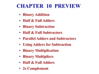
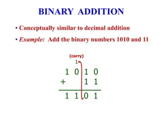
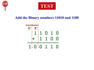
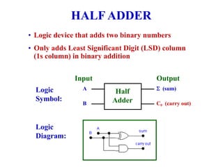
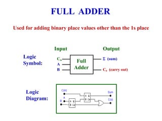
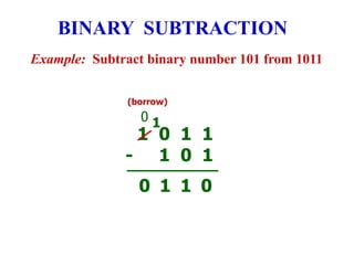
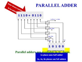
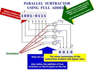
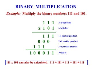
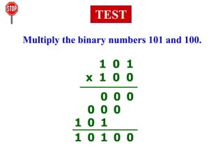
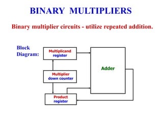
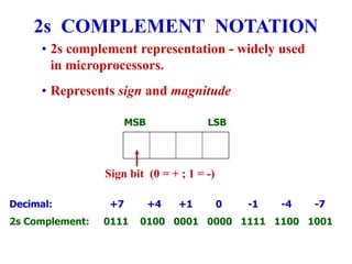
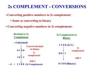
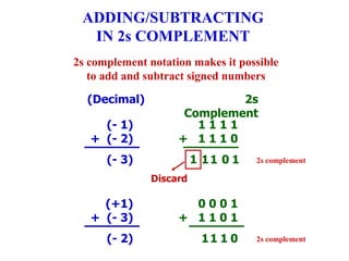
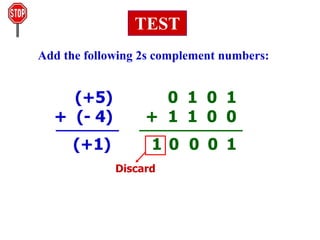
Digital Electronics
Principles & Applications
Fifth Edition
Chapter 10
Arithmetic Circuits
©1999 Glencoe/McGraw-Hill
Roger L. Tokheim
CHAPTER 10 PREVIEW
• Binary Addition
• Half & Full Adders
• Binary Subtraction
• Half & Full Subtractors
• Parallel Adders and Subtractors
• Using Adders for Subtraction
• Binary Multiplication
• Binary Multipliers
• Half & Full Adders
• 2s Complement
• Conceptually similar to decimal addition
• Example: Add the binary numbers 1010 and 11
BINARY ADDITION
1 0 1 0
+ 1 1
(carry)
1
1
0
1
1
Add the Binary numbers 11010 and 1100
TEST
1 1 0 1 0
+ 1 1 0 0
(carry)
1
0
1
1
0
0
1
(carry)
1
• Logic device that adds two binary numbers
• Only adds Least Significant Digit (LSD) column
(1s column) in binary addition
HALF ADDER
A
B
 (sum)
C0 (carry out)
Half
Adder
Input Output
Logic
Symbol:
Logic
Diagram:
Used for adding binary place values other than the 1s place
FULL ADDER
Logic
Symbol:
Logic
Diagram:
A
B
 (sum)
C0 (carry out)
Full
Adder
Input Output
Cin
Example: Subtract binary number 101 from 1011
BINARY SUBTRACTION
1 0 1 1
- 1 0 1
(borrow)
0
1
1
0
1
0
Subtract binary number 11 from 1010
TEST
1 0 1 0
- 1 1
1
1
1
0
1
10
0 0
01
1
Subtracts LSD column in binary subtraction
HALF SUBTRACTOR
A
B
Di (difference)
B0 (borrow out)
Half
Subtractor
Input Output
Logic
Symbol:
Logic
Diagram:
Used for subtracting binary place
values other than the 1s place
FULL SUBTRACTOR
Logic
Symbol:
Logic
Diagram:
A
B
Di (difference)
B0 (borrow out)
Full
Subtractor
Input Output
Bin
A
B
Di
B0
H. S.
H. S.
Bin
• Use half adder for LSD
• Use full adder for other digits
PARALLEL ADDING
A2 A1 A0
+ B2 B1 B0
PARALLELADDER
1s place uses half-adder
2s, 4s, 8s places use full adders
SUM appears here
0 0 1 1 + 1 0 0 0
0 1 0 1 1
1 1 0 0 + 1 1 1 1
1 1 0 1 1
1 0 1 0 0
1 1 1 0 + 0 1 1 0
Parallel adders are available in IC form.
PARALLEL SUBTRACTOR
USING FULL ADDERS
Note the use of four full adder
circuits
Also notice the addition of four
inverters on the B inputs to the FAs
Inverters
1 1 1 1 - 0 0 1 1
The result (difference) of the
subtraction problem will appear here.
1 1 0 0
1 0 0 1 - 0 1 1 1
0 0 1 0
Example: Multiply the binary numbers 111 and 101.
BINARY MULTIPLICATION
1
1
1
0
0
0
1
1
1
1
1
0
0
0
1
1 1 1
x 1 0 1
Multiplicand
Multiplier
1st partial product
2nd partial product
3rd partial product
Product
111 x 101 can also be calculated: 111 + 111 + 111 + 111 + 111
Multiply the binary numbers 101 and 100.
1 0 1
x 1 0 0
0
0
0
0
0
0
1
0
1
0
0
1
0
1
TEST
Binary multiplier circuits - utilize repeated addition.
BINARY MULTIPLIERS
Block
Diagram:
Multiplicand
register
Multiplier
down counter
Product
register
Adder
• 2s complement representation - widely used
in microprocessors.
• Represents sign and magnitude
2s COMPLEMENT NOTATION
Decimal: +7 +4 +1 0 -1 -4 -7
2s Complement: 0111 0100 0001 0000 1111 1100 1001
MSB LSB
Sign bit (0 = + ; 1 = -)
• Converting positive numbers to 2s complement:
• Same as converting to binary
• Converting negative numbers to 2s complement:
2s COMPLEMENT - CONVERSIONS
- 4 (decimal)
0 1 0 0
1 0 1 1
- 4 = 1 1 0 0 (2s Complement)
Decimal to 2s
Complement
Convert decimal
to binary
1s
complement
Add 1
2s Complement to
Binary
1 1 0 0 (2s C)
0 0 1 1
0 1 0 0 (Binary)
1s
complement
Add 1
2s complement notation makes it possible
to add and subtract signed numbers
ADDING/SUBTRACTING
IN 2s COMPLEMENT
(- 1)
+ (- 2)
(- 3)
1 1 1 1
+ 1 1 1 0
1
0
1
1
1
Discard
(+1)
+ (- 3)
(- 2)
0 0 0 1
+ 1 1 0 1
0
1
1
1
(Decimal) 2s
Complement
2s complement
2s complement
Add the following 2s complement numbers:
0 1 0 1
+ 1 1 0 0
1
0
0
TEST
0
1
(+5)
+ (- 4)
(+1)
Discard
PRACTICAL SUGGESTION
FOR BINARY MATH
• Use a scientific calculator.
• Most scientific calculators have
DEC, BIN, OCT, and HEX modes
and can either convert between
codes or perform arithmetic in
different number systems.
• Most scientific calculators also
have other functions that are
valuable in digital electronics
such as AND, OR, NOT, XOR,
and XNOR logic functions.

tCh10.ppt

  • 1.
    Digital Electronics Principles &Applications Fifth Edition Chapter 10 Arithmetic Circuits ©1999 Glencoe/McGraw-Hill Roger L. Tokheim
  • 2.
    CHAPTER 10 PREVIEW •Binary Addition • Half & Full Adders • Binary Subtraction • Half & Full Subtractors • Parallel Adders and Subtractors • Using Adders for Subtraction • Binary Multiplication • Binary Multipliers • Half & Full Adders • 2s Complement
  • 3.
    • Conceptually similarto decimal addition • Example: Add the binary numbers 1010 and 11 BINARY ADDITION 1 0 1 0 + 1 1 (carry) 1 1 0 1 1
  • 4.
    Add the Binarynumbers 11010 and 1100 TEST 1 1 0 1 0 + 1 1 0 0 (carry) 1 0 1 1 0 0 1 (carry) 1
  • 5.
    • Logic devicethat adds two binary numbers • Only adds Least Significant Digit (LSD) column (1s column) in binary addition HALF ADDER A B  (sum) C0 (carry out) Half Adder Input Output Logic Symbol: Logic Diagram:
  • 6.
    Used for addingbinary place values other than the 1s place FULL ADDER Logic Symbol: Logic Diagram: A B  (sum) C0 (carry out) Full Adder Input Output Cin
  • 7.
    Example: Subtract binarynumber 101 from 1011 BINARY SUBTRACTION 1 0 1 1 - 1 0 1 (borrow) 0 1 1 0 1 0
  • 8.
    Subtract binary number11 from 1010 TEST 1 0 1 0 - 1 1 1 1 1 0 1 10 0 0 01 1
  • 9.
    Subtracts LSD columnin binary subtraction HALF SUBTRACTOR A B Di (difference) B0 (borrow out) Half Subtractor Input Output Logic Symbol: Logic Diagram:
  • 10.
    Used for subtractingbinary place values other than the 1s place FULL SUBTRACTOR Logic Symbol: Logic Diagram: A B Di (difference) B0 (borrow out) Full Subtractor Input Output Bin A B Di B0 H. S. H. S. Bin
  • 11.
    • Use halfadder for LSD • Use full adder for other digits PARALLEL ADDING A2 A1 A0 + B2 B1 B0
  • 12.
    PARALLELADDER 1s place useshalf-adder 2s, 4s, 8s places use full adders SUM appears here 0 0 1 1 + 1 0 0 0 0 1 0 1 1 1 1 0 0 + 1 1 1 1 1 1 0 1 1 1 0 1 0 0 1 1 1 0 + 0 1 1 0 Parallel adders are available in IC form.
  • 13.
    PARALLEL SUBTRACTOR USING FULLADDERS Note the use of four full adder circuits Also notice the addition of four inverters on the B inputs to the FAs Inverters 1 1 1 1 - 0 0 1 1 The result (difference) of the subtraction problem will appear here. 1 1 0 0 1 0 0 1 - 0 1 1 1 0 0 1 0
  • 14.
    Example: Multiply thebinary numbers 111 and 101. BINARY MULTIPLICATION 1 1 1 0 0 0 1 1 1 1 1 0 0 0 1 1 1 1 x 1 0 1 Multiplicand Multiplier 1st partial product 2nd partial product 3rd partial product Product 111 x 101 can also be calculated: 111 + 111 + 111 + 111 + 111
  • 15.
    Multiply the binarynumbers 101 and 100. 1 0 1 x 1 0 0 0 0 0 0 0 0 1 0 1 0 0 1 0 1 TEST
  • 16.
    Binary multiplier circuits- utilize repeated addition. BINARY MULTIPLIERS Block Diagram: Multiplicand register Multiplier down counter Product register Adder
  • 17.
    • 2s complementrepresentation - widely used in microprocessors. • Represents sign and magnitude 2s COMPLEMENT NOTATION Decimal: +7 +4 +1 0 -1 -4 -7 2s Complement: 0111 0100 0001 0000 1111 1100 1001 MSB LSB Sign bit (0 = + ; 1 = -)
  • 18.
    • Converting positivenumbers to 2s complement: • Same as converting to binary • Converting negative numbers to 2s complement: 2s COMPLEMENT - CONVERSIONS - 4 (decimal) 0 1 0 0 1 0 1 1 - 4 = 1 1 0 0 (2s Complement) Decimal to 2s Complement Convert decimal to binary 1s complement Add 1 2s Complement to Binary 1 1 0 0 (2s C) 0 0 1 1 0 1 0 0 (Binary) 1s complement Add 1
  • 19.
    2s complement notationmakes it possible to add and subtract signed numbers ADDING/SUBTRACTING IN 2s COMPLEMENT (- 1) + (- 2) (- 3) 1 1 1 1 + 1 1 1 0 1 0 1 1 1 Discard (+1) + (- 3) (- 2) 0 0 0 1 + 1 1 0 1 0 1 1 1 (Decimal) 2s Complement 2s complement 2s complement
  • 20.
    Add the following2s complement numbers: 0 1 0 1 + 1 1 0 0 1 0 0 TEST 0 1 (+5) + (- 4) (+1) Discard
  • 21.
    PRACTICAL SUGGESTION FOR BINARYMATH • Use a scientific calculator. • Most scientific calculators have DEC, BIN, OCT, and HEX modes and can either convert between codes or perform arithmetic in different number systems. • Most scientific calculators also have other functions that are valuable in digital electronics such as AND, OR, NOT, XOR, and XNOR logic functions.