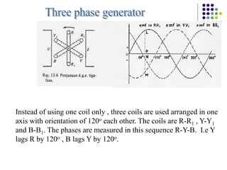
1) A three-phase system uses three coils arranged 120 degrees apart to induce current. This solves the problem of induction motors not being able to start on their own with a single-phase system.
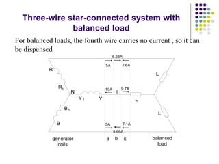
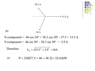
2) The three-phase system can be represented by a wye or delta circuit connection. In a wye connection, the three phase currents sum to zero at the neutral point.
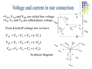
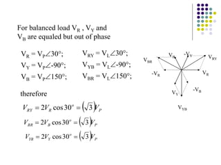
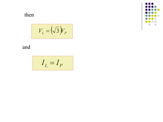
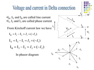
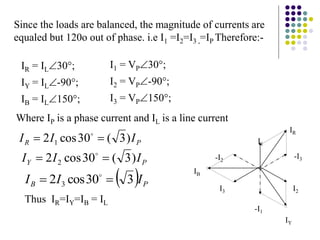
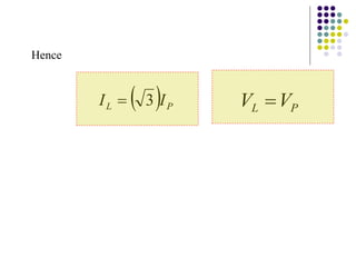
3) In a balanced three-phase system, the phase voltages and currents are equal in magnitude but 120 degrees out of phase. This results in the line voltages and currents being equal as well.

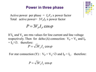
![Flux density
B [T]
l
d
L
A
M
N
Generator for single phase
Current induces in the coil as the
coil moves in the magnetic field
Current produced at terminal
Note
Induction motor cannot start
by itself. This problem is
solved by introducing three
phase system](https://image.slidesharecdn.com/10threephasesystem-221108184917-9fda6cc4/85/10-three-phase-system-ppt-2-320.jpg)
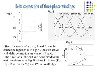
![The circuit can be simplified as follows, where R1 can be
connected to Y and Y1 can be connected to B. In this case
the circuit is reduced to 4 wires.
B
Y
R
1
RB e
e
e
e
)]
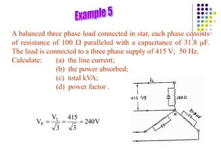
240
sin(
)
120
sin(
[sin
Em
t
t
t
120
sin
t
cos
120
cos
t
sin
t
[sin
m
E
]
240
sin
t
cos
240
cos
t
sin
]
t
866
.
0
t
sin
5
.
0
t
cos
866
.
0
t
sin
5
0
t
[sin
kos
.
Em
0
Since the total emf is zero, R and B1 can be connected together, thus
we arrive with delta connection system.
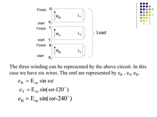
Finish
Finish
Finish
start
start
start
R
R1
Y
Y1
B
B1
eR+eY+eB
eR
eY
eB](https://image.slidesharecdn.com/10threephasesystem-221108184917-9fda6cc4/85/10-three-phase-system-ppt-5-320.jpg)
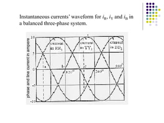
![t
sin
i
m
R I
)
120
t
sin(
i
-
Im
Y
)
240
t
sin(
i
-
Im
B
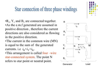
The instantaneous current in loads L1 , L2 and L3 are
B
Y
R
N i
i
i
i
0
)]
240
t
sin(
)
120
t
sin(
t
[sin
m
I
R
R
1
Y Y
1
B
B1
Line
conductors
R
N
iR
iB
iY
iR
+iY
+iB
L3
L1
L2
B
Y](https://image.slidesharecdn.com/10threephasesystem-221108184917-9fda6cc4/85/10-three-phase-system-ppt-8-320.jpg)