Introduction
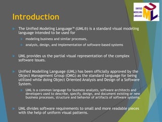
The UnifiedModeling Language (UML®) is a standard visual modeling
language intended to be used for
modeling business and similar processes,
analysis, design, and implementation of software-based systems
UML provides us the partial visual representation of the complex
software issues.
Unified Modelling Language (UML) has been officially approved by the
Object Management Group (OMG) as the standard language for being
utilized while doing Object Oriented Analysis and Design of a Software
System.
UML is a common language for business analysts, software architects and
developers used to describe, specify, design, and document existing or new
business processes, structure and behavior of artifacts of software systems.
UML divides software requirements to small and more readable pieces
with the help of uniform visual patterns.
3.
Introduction
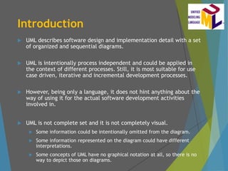
UML describessoftware design and implementation detail with a set
of organized and sequential diagrams.
UML is intentionally process independent and could be applied in
the context of different processes. Still, it is most suitable for use
case driven, iterative and incremental development processes.
However, being only a language, it does not hint anything about the
way of using it for the actual software development activities
involved in.
UML is not complete set and it is not completely visual.
Some information could be intentionally omitted from the diagram.
Some information represented on the diagram could have different
interpretations.
Some concepts of UML have no graphical notation at all, so there is no
way to depict those on diagrams.
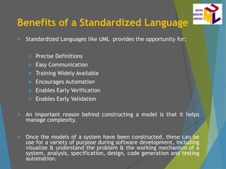
Benefits of aStandardized Language
Standardized Languages like UML provides the opportunity for:
Precise Definitions
Easy Communication
Training Widely Available
Encourages Automation
Enables Early Verification
Enables Early Validation
An important reason behind constructing a model is that it helps
manage complexity.
Once the models of a system have been constructed, these can be
use for a variety of purpose during software development, including
visualize & understand the problem & the working mechanism of a
system, analysis, specification, design, code generation and testing
automation.
8.
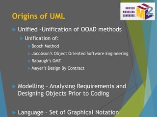
Origins of UML
Unified –Unification of OOAD methods
Unification of:
Booch Method
Jacobson’s Object Oriented Software Engineering
Rabaugh’s OMT
Meyer’s Design By Contract
Modelling – Analysing Requirements and
Designing Objects Prior to Coding
Language – Set of Graphical Notation
9.
Evolution of UML
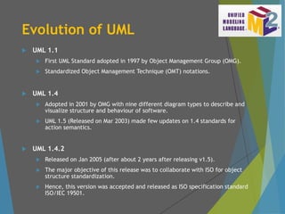
UML 1.1
First UML Standard adopted in 1997 by Object Management Group (OMG).
Standardized Object Management Technique (OMT) notations.
UML 1.4
Adopted in 2001 by OMG with nine different diagram types to describe and
visualize structure and behaviour of software.
UML 1.5 (Released on Mar 2003) made few updates on 1.4 standards for
action semantics.
UML 1.4.2
Released on Jan 2005 (after about 2 years after releasing v1.5).
The major objective of this release was to collaborate with ISO for object
structure standardization.
Hence, this version was accepted and released as ISO specification standard
ISO/IEC 19501.
10.
Evolution of UML
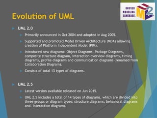
UML 2.0
Primarily announced in Oct 2004 and adopted in Aug 2005.
Supported and promoted Model Driven Architecture (MDA) allowing
creation of Platform Independent Model (PIM).
Introduced new diagrams: Object Diagrams, Package Diagrams,
composite structure diagram, interaction overview diagrams, timing
diagrams, profile diagrams and communication diagrams (renamed from
Collaboration Diagram).
Consists of total 13 types of diagrams.
UML 2.5
Latest version available released on Jun 2015.
UML 2.5 includes a total of 14 types of diagrams, which are divided into
three groups or diagram types: structure diagrams, behavioral diagrams
and. interaction diagrams.
11.
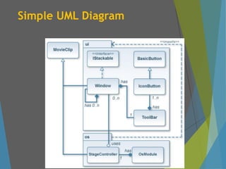
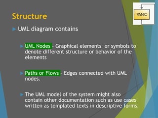
Structure
UML diagramcontains
UML Nodes - Graphical elements or symbols to
denote different structure or behavior of the
elements
Paths or Flows – Edges connected with UML
nodes.
The UML model of the system might also
contain other documentation such as use cases
written as templated texts in descriptive forms.
12.
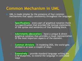
Common Mechanism inUML
UML is made simpler by the presence of four common
mechanisms that apply consistently throughout the language:
1. Specifications – every part of graphical notation there
is a specification that provides the textual statements
of the syntax and semantics of that building block.
2. Adornments (decoration) – have a unique & direct
graphical notation that provides a visual representation
of the most important aspects of the element.
3. Common divisions – in modeling OOS, the world gets
divided in at least a couple of ways.
4. Extensively - provide standard language writing the
S/W blueprints, to extend the language in controlled
ways
13.
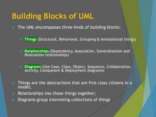
Building Blocks ofUML
The UML encompasses three kinds of building blocks:
Things (Structural, Behavioral, Grouping & Annotational things)
Relationships (Dependency, Association, Generalization and
Realization relationships)
Diagrams (Use Case, Class, Object, Sequence, Collaboration,
Activity, Component & Deployment diagrams)
Things are the abstractions that are first class citizens in a
model;
Relationships ties these things together;
Diagrams group interesting collections of things
14.
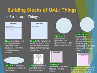
Building Blocks ofUML: Things
Structural Things:
Class: Description of a
set of objects that
share the same
attributes, operations,
relationships and
semantics
Object: The notation is
similar to that of class,
only difference is that
object name is always
underlined.
Interface: A
collection of
operations that
specify a service of a
class or component
Collaboration:
Presents the
interaction between
things that is done to
meet the goal,
symbolized as a dotted
ellipse with its name
inside it.
Use Case: It portrays a
set of actions executed
by a system.
Actor: Represents a
user that interacts
with the system.
Component:
Represents a user that
interacts with the
system.
Node: Physical resource that
exists in run time, typically
computational resource.
15.
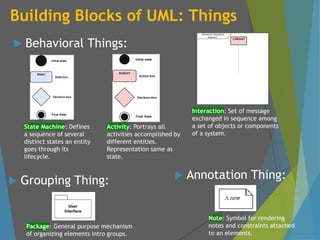
Building Blocks ofUML: Things
Behavioral Things:
State Machine: Defines
a sequence of several
distinct states an entity
goes through its
lifecycle.
Activity: Portrays all
activities accomplished by
different entities.
Representation same as
state.
Interaction: Set of message
exchanged in sequence among
a set of objects or components
of a system.
Package: General purpose mechanism
of organizing elements intro groups.
Note: Symbol for rendering
notes and constraints attached
to an elements.
Grouping Thing: Annotation Thing:
16.
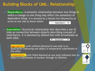
Building Blocks ofUML: Relationship
Dependency: A semantic relationship between two things in
which a change to one thing may affect the semantics of
dependent thing. It is denoted by a dotted line followed by an
arrow at one side as shown below
Association: Structural relationship that describes a set of
links as connection between objects describing concept of
inheritance. It is denoted by dotted line with arrowheads on
both sides.
Aggregation: (with unfilled diamond at one end) is an
association indicating one object is temporarily subordinate of
the other.
Composition: (with filled diamond at one end) indicates that an
object is subordinate of another through its lifetime.
17.
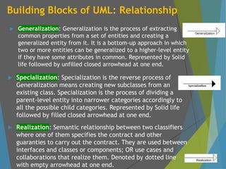
Building Blocks ofUML: Relationship
Generalization: Generalization is the process of extracting
common properties from a set of entities and creating a
generalized entity from it. It is a bottom-up approach in which
two or more entities can be generalized to a higher-level entity
if they have some attributes in common. Represented by Solid
life followed by unfilled closed arrowhead at one end.
Specialization: Specialization is the reverse process of
Generalization means creating new subclasses from an
existing class. Specialization is the process of dividing a
parent-level entity into narrower categories accordingly to
all the possible child categories. Represented by Solid life
followed by filled closed arrowhead at one end.
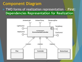
Realization: Semantic relationship between two classifiers
where one of them specifies the contract and other
guaranties to carry out the contract. They are used between
interfaces and classes or components; OR use cases and
collaborations that realize them. Denoted by dotted line
with empty arrowhead at one end.
18.
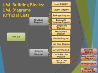
UML Building Blocks:
UMLDiagrams
(Official List)
UML 2.5
Structure
Diagrams
Class Diagram
Object Diagram
Package Diagram
Composite
Structure Diagram
Component
Diagram
Deployment
Diagram
Profile Diagram
Behavior
Diagrams
Use Case Diagram
Activity Diagram
State Machine
Diagram
Interaction
Diagram
Sequence
Diagram
Communication
Diagram
Timing Diagram
Interaction
Overview Dia.
19.
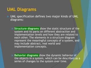
UML Diagrams
UMLspecification defines two major kinds of UML
diagrams:
Structure diagrams show the static structure of the
system and its parts on different abstraction and
implementation levels and how they are related to
each other. The elements in a structure diagram
represent the meaningful concepts of a system, and
may include abstract, real world and
implementation concepts.
Behavior diagrams show the dynamic behavior of
the objects in a system, which can be described as a
series of changes to the system over time.
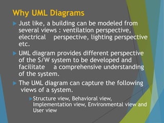
Why UML Diagrams
Just like, a building can be modeled from
several views : ventilation perspective,
electrical perspective, lighting perspective
etc.
UML diagram provides different perspective
of the S/W system to be developed and
facilitate a comprehensive understanding
of the system.
The UML diagram can capture the following
views of a system.
Structure view, Behavioral view,
Implementation view, Environmental view and
User view
22.
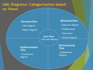
UML Diagrams: Categorizationbased
on Views
StructureView
- Class diagram
- Object diagram
BehavioralView
- Sequence diagram
- Collaboration
- State-chart
- Activity diagram
UserView
- Use case diagram
Implementation
View
- Component
diagram
Environmental
View
- Deployment
Diagram
23.
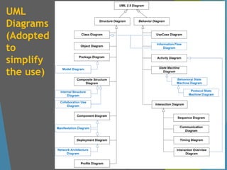
UML Diagrams
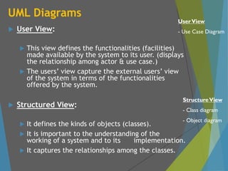
UserView:
This view defines the functionalities (facilities)
made available by the system to its user. (displays
the relationship among actor & use case.)
The users’ view capture the external users’ view
of the system in terms of the functionalities
offered by the system.
Structured View:
It defines the kinds of objects (classes).
It is important to the understanding of the
working of a system and to its implementation.
It captures the relationships among the classes.
StructureView
- Class diagram
- Object diagram
UserView
- Use Case Diagram
24.
UML Diagrams
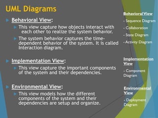
BehavioralView:
This view capture how objects interact with
each other to realize the system behavior.
The system behavior captures the time-
dependent behavior of the system. It is called
Interaction diagram.
Implementation View:
This view capture the important components
of the system and their dependencies.
Environmental View:
This view models how the different
components of the system and their
dependencies are setup and organize.
Implementation
View
- Component
Diagram
BehavioralView
- Sequence Diagram
- Collaboration
- State Diagram
- Activity Diagram
Environmental
View
- Deployment
Diagram
25.
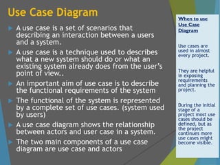
Use Case Diagram
A use case is a set of scenarios that
describing an interaction between a users
and a system.
A use case is a technique used to describes
what a new system should do or what an
existing system already does from the user’s
point of view..
An important aim of use case is to describe
the functional requirements of the system
The functional of the system is represented
by a complete set of use cases. (system used
by users)
A use case diagram shows the relationship
between actors and user case in a system.
The two main components of a use case
diagram are use case and actors
When to use
Use Case
Diagram
Use cases are
used in almost
every project.
They are helpful
in exposing
requirements
and planning the
project.
During the initial
stage of a
project most use
cases should be
defined, but as
the project
continues more
use cases might
become visible.
26.
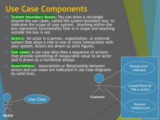
Use Case Components
System boundary boxes: You can draw a rectangle
around the use cases, called the system boundary box, to
indicates the scope of your system. Anything within the
box represents functionality that is in scope and anything
outside the box is not.
Actors: An actor is a person, organization, or external
system that plays a role in one or more interactions with
your system. Actors are drawn as stick figures.
Use cases: A use case describes a sequence of actions
that provide something of measurable value to an actor
and is drawn as a horizontal ellipse.
Associations: Associations or Relationship between
actors and use cases are indicated in use case diagrams
by solid lines.
Actor
Use Case
Browse book
catalogue
Located Book by
Title or author
Request
Unlisted book
Customer
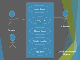
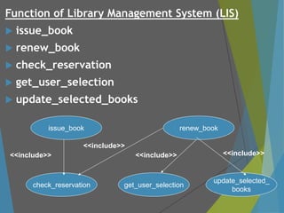
Function of LibraryManagement System (LIS)
issue_book
renew_book
check_reservation
get_user_selection
update_selected_books
issue_book
get_user_selection
update_selected_
books
renew_book
check_reservation
<<include>>
<<include>>
<<include>> <<include>>
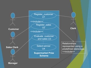
30.
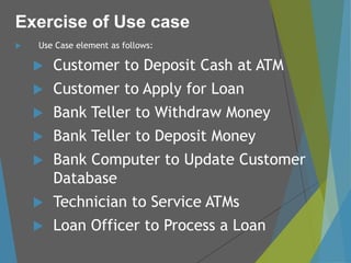
Use Caseelement as follows:
Customer to Deposit Cash at ATM
Customer to Apply for Loan
Bank Teller to Withdraw Money
Bank Teller to Deposit Money
Bank Computer to Update Customer
Database
Technician to Service ATMs
Loan Officer to Process a Loan
Exercise of Use case
31.
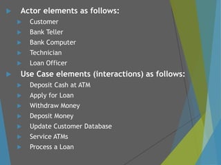
Actor elementsas follows:
Customer
Bank Teller
Bank Computer
Technician
Loan Officer
Use Case elements (interactions) as follows:
Deposit Cash at ATM
Apply for Loan
Withdraw Money
Deposit Money
Update Customer Database
Service ATMs
Process a Loan
32.
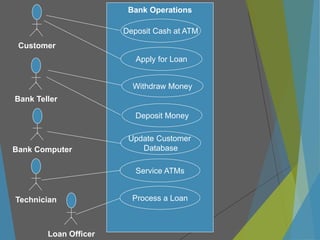
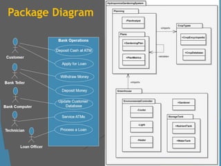
Deposit Cash atATM
Apply for Loan
Withdraw Money
Deposit Money
Update Customer
Database
Customer
Bank Operations
Service ATMs
Process a Loan
Bank Teller
Bank Computer
Technician
Loan Officer
33.
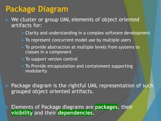
Package Diagram
Wecluster or group UML elements of object oriented
artifacts for:
Clarity and understanding in a complex software development
To represent concurrent model use by multiple users
To provide abstraction at multiple levels from systems to
classes in a component
To support version control
To Provide encapsulation and containment supporting
modularity
Package diagram is the rightful UML representation of such
grouped object oriented artifacts.
Elements of Package diagrams are packages, their
visibility and their dependencies.
34.
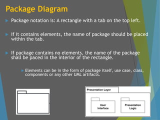
Package Diagram
Packagenotation is: A rectangle with a tab on the top left.
If it contains elements, the name of package should be placed
within the tab.
If package contains no elements, the name of the package
shall be paced in the interior of the rectangle.
Elements can be in the form of package itself, use case, class,
components or any other UML artifacts.
35.
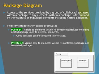
Package Diagram
Accessto the services provided by a group of collaborating classes
within a package to any elements with in a package is determined
by the visibility of individual elements including nested packages.
Visibility can be either public or private:
Public (+): Visible to elements within its containing package including
nested packages and to external elements.
Public packages can be compared to Interfaces.
Private (-): Visible only to elements within its containing package and
to nested packages.
36.
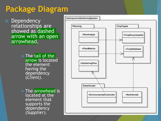
Package Diagram
Dependency
relationshipsare
showed as dashed
arrow with an open
arrowhead.
The tail of the
arrow is located
the element
having the
dependency
(Client).
The arrowhead is
located at the
element that
supports the
dependency
(Supplier).
37.
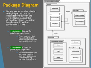
Package Diagram
Dependenciescan be labeled
to highlight the type of
dependency between the
elements by placing the
dependency type – denoted
by a keyword – within
guillemets (<< >>)
<<import>> is used for
public package import.
Other elements that
has visibility in the
importing package can
see the imported one.
<<access>> is used for
private package import.
No other elements can
see those elements
that have been added
to the importing
package’s namespace.
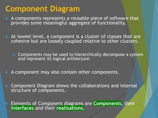
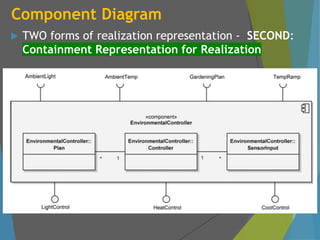
Component Diagram
Acomponents represents a reusable piece of software that
provides some meaningful aggregate of functionality.
At lowest level, a component is a cluster of classes that are
cohesive but are loosely coupled relative to other clusters.
Components may be used to hierarchically decompose a system
and represent its logical arthiecture.
A component may also contain other components.
Component Diagram shows the collaborations and internal
structure of components.
Elements of Component diagrams are Components, their
interfaces and their realizations.
42.
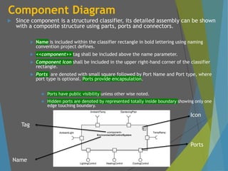
Component Diagram
Sincecomponent is a structured classifier, its detailed assembly can be shown
with a composite structure using parts, ports and connectors.
Name is included within the classifier rectangle in bold lettering using naming
convention project defines.
<<component>> tag shall be included above the name parameter.
Component Icon shall be included in the upper right-hand corner of the classifier
rectangle.
Ports are denoted with small square followed by Port Name and Port type, where
port type is optional. Ports provide encapsulation.
Ports have public visibility unless other wise noted.
Hidden ports are denoted by represented totally inside boundary showing only one
edge touching boundary.
Icon
Ports
Name
Tag
43.
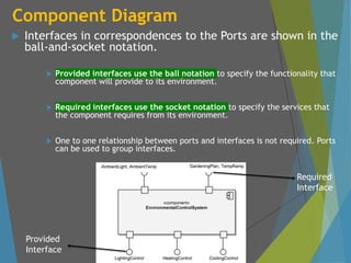
Component Diagram
Interfacesin correspondences to the Ports are shown in the
ball-and-socket notation.
Provided interfaces use the ball notation to specify the functionality that
component will provide to its environment.
Required interfaces use the socket notation to specify the services that
the component requires from its environment.
One to one relationship between ports and interfaces is not required. Ports
can be used to group interfaces.
Required
Interface
Provided
Interface
44.
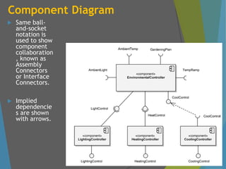
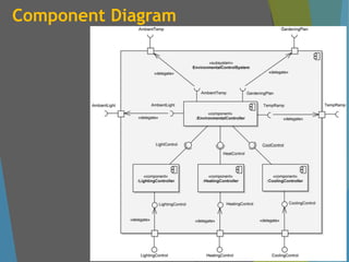
Component Diagram
Sameball-
and-socket
notation is
used to show
component
collaboration
, known as
Assembly
Connectors
or Interface
Connectors.
Implied
dependencie
s are shown
with arrows.
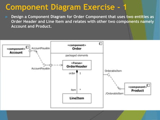
Component Diagram Exercise- 1
Design a Component Diagram for Order Component that uses two entities as
Order Header and Line Item and relates with other two components namely
Account and Product.
50.
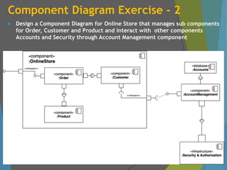
Component Diagram Exercise- 2
Design a Component Diagram for Online Store that manages sub components
for Order, Customer and Product and interact with other components
Accounts and Security through Account Management component
51.
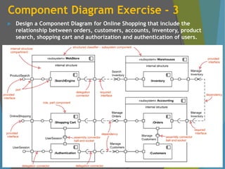
Component Diagram Exercise- 3
Design a Component Diagram for Online Shopping that include the
relationship between orders, customers, accounts, inventory, product
search, shopping cart and authorization and authentication of users.
52.
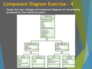
Component Diagram Exercise- 4
Design Use Case, Package and Component Diagrams for situationship
presented by Class Hierarchy below:
Catalogue number
Acquisition date
Cost
Type
Status
Number of copies
Library item
Acquire ()
Catalogue ()
Dispose ()
Issue ()
Return ()
Author
Edition
Publication date
ISBN
Book
Year
Issue
Magazine
Director
Date of release
Distributor
Film
Version
Platform
Computer
program
Title
Publisher
Published item
Title
Medium
Recorded item
53.
Object Oriented DevelopmentLifecycle
Software development necessities demand a lot of brainstorming with
a balancing act of a unique set of functional and performance
requirements demanding the full creative energies of development
teams.
It is not possible to achieve an ideal scenario on one-go in typical cases
demanding multiple adoptive approaches where each successive cycles
or iterations adopts the lesson leant on earlier cycle.
Software development, like any human activity that requires creativity
and innovation, demands an iterative and incremental process that
relies on the experience, intelligence and talent of each team member.
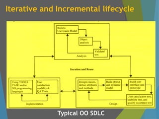
Iterative and incremental development is where the functionality of
the system is developed in a successive series of releases (iterative) of
increasing completeness (incremental). A release may be external
(available to the customer) or internal (not available to the customer).
54.
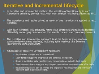
Iterative and Incrementallifecycle
In Iterative and Incremental method, the selection of functionality in each
iteration is driven by project risks, with most critical risks being addressed first.
The experience and results gained as result of one iteration are applied to next
iteration.
With each iteration, you gradually refine your strategies and tactical decisions,
ultimately converging on a solution that meets the end user’s real requirement.
The iterative and incremental approach is at the heard of most modern
software development methods, including agile methods like Extreme
Programming (XP) and SCRUM.
Advantages of Iterative Development Approach:
Requirement changes are accommodated.
Each iteration supports progressive and continual integration.
Reuse is facilitated as key architectural components are actually built early.
Team members learn along the way. Project personal are employed more effectively.
Development process can be refined and improved. Risk migration and redressal is
easy with each evolving iterations.
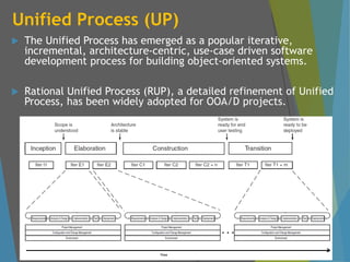
Unified Process (UP)
The Unified Process has emerged as a popular iterative,
incremental, architecture-centric, use-case driven software
development process for building object-oriented systems.
Rational Unified Process (RUP), a detailed refinement of Unified
Process, has been widely adopted for OOA/D projects.
57.
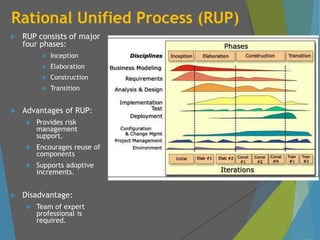
Rational Unified Process(RUP)
RUP consists of major
four phases:
Inception
Elaboration
Construction
Transition
Advantages of RUP:
Provides risk
management
support.
Encourages reuse of
components
Supports adoptive
increments.
Disadvantage:
Team of expert
professional is
required.
58.
Rational Unified Process(RUP)
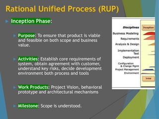
Inception Phase:
Purpose: To ensure that product is viable
and feasible on both scope and business
value.
Activities: Establish core requirements of
system, obtain agreement with customer,
understand key risks, decide development
environment both process and tools
Work Products: Project Vision, behavioral
prototype and architectural mechanisms
Milestone: Scope is understood.
59.
Rational Unified Process(RUP)
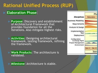
Elaboration Phase:
Purpose: Discovery and establishment
of Architectural Framework that
provides foundation for all the
iterations. Also mitigate highest risks.
Activities: Designing architectural
framework, testing framework, refining
the framework.
Work Products: The architecture is
validated.
Milestone: Architecture is stable.
60.
Rational Unified Process(RUP)
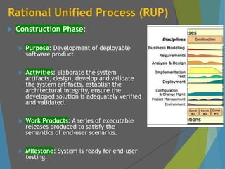
Construction Phase:
Purpose: Development of deployable
software product.
Activities: Elaborate the system
artifacts, design, develop and validate
the system artifacts, establish the
architectural integrity, ensure the
developed solution is adequately verified
and validated.
Work Products: A series of executable
releases produced to satisfy the
semantics of end-user scenarios.
Milestone: System is ready for end-user
testing.
61.
Rational Unified Process(RUP)
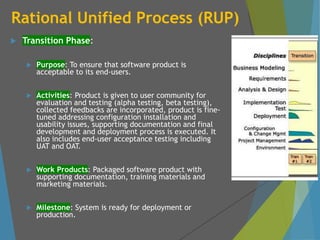
Transition Phase:
Purpose: To ensure that software product is
acceptable to its end-users.
Activities: Product is given to user community for
evaluation and testing (alpha testing, beta testing),
collected feedbacks are incorporated, product is fine-
tuned addressing configuration installation and
usability issues, supporting documentation and final
development and deployment process is executed. It
also includes end-user acceptance testing including
UAT and OAT.
Work Products: Packaged software product with
supporting documentation, training materials and
marketing materials.
Milestone: System is ready for deployment or
production.