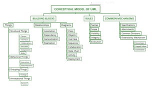
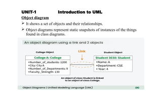
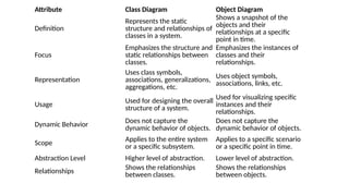
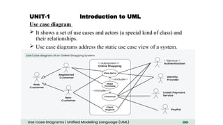
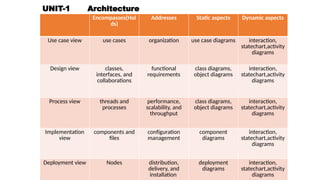
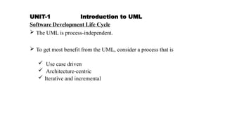
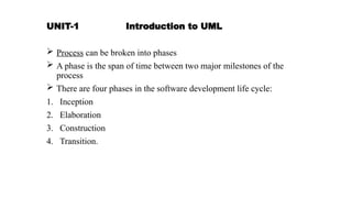
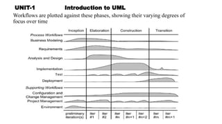
UNIT-1 Introduction to UML
Why we model:
Modeling is a central part of all the activities that leads to the
deployment of good software. Models are built to
 Communicate
 Visualize and control
 Better
 Manage risk.
UNIT-1 Introduction to UML
Improtance of Modeling:
What is Model:
 A model is a simplification of reality.
 It provides the blueprints of the system.
 Models may include detailed plans, as well as more general plans.
UNIT-1 Introduction to UML
Four aims achieved through modeling:
1. Models help us to visualize a system
2. Models permit us to specify the structure or behavior of a system.
3. Models give us a template for constructing
4. Models document the decisions
UNIT-1 Introduction to UML
Principles of Modeling :
1. The choice of what models to create has a profound
influence on how a problem is attacked and how a
solution is shaped.
OR
Choose your models well
UNIT-1 Introduction to UML
2. Every model may be expressed at different levels of
precision.
UNIT-1 Introduction to UML
3. The best models are connected to reality.
UNIT-1 Introduction to UML
4. No single model is sufficient. Every nontrivial
system is best approached through a small set of
nearly independent models
UNIT-1 Introduction to UML
Object-Oriented Modeling:
In software, there are several ways to approach a model.
1. An algorithmic perspective
2. An object-oriented perspective.
UNIT-1 Introduction to UML
Introduction the UML:
 Unified Modeling Language (UML) is a general purpose modeling
language.
 The main aim of UML is to define a standard way to visualize
 UML is not a programming language, it is a visual language.
 We use UML diagrams to portray the behavior and structure of a
system.
UNIT-1 Introduction to UML
Introduction the UML:
 A modeling language is a language whose vocabulary and rules focus
on the conceptual and physical representation of a system
 The UML may be used to
1. Visualize
2. Specify
3. Construct
4. Document the artifacts of a software intensive system
UNIT-1 Introduction to UML
A Conceptual
Model of the UML:
Three major
elements:
1. Basic building
blocks
2. The rules
3. Common
mechanisms
UNIT-1 Introduction to UML
Building Blocks of the UML:
The vocabulary of the UML has three kinds of building blocks:
1. Things
2. Relationships
3. Diagrams
UNIT-1 Introduction to UML
Things in the UML
There are four kinds of things in the UML:
1. Structural things
2. Behavioral things
3. Grouping things
4. Annotational things
UNIT-1 Introduction to UML
Structural Things:
 These are the static parts of a model, representing elements that are
either conceptual or physical.
 There are seven kinds of structural things.
1. Classes
2. Interface
3. Collaboration
4. Use case
5. Active class
6. Component
7. Node
UNIT-1 Introduction to UML
1.Class represents a set of objects that share the same
attributes,operations,relationships and semantics. having similar responsibilities.
2.Interface − Interface defines a collection of operations, which specify the
service of a class or component
3.Collaboration −Collaboration defines an interaction and society of roles and
other elements together to provide cooperative work
UNIT-1 Introduction to UML
4.Use case −Use case represents a set of actions performed by a system
for a specific goal that yields an observable result of value to a particular
actor.
5.Component −Component describes the physical and replaceable part
of a system and provides the realization of a set of interfaces.
UNIT-1 Introduction to UML
6. Node − A node can be defined as a physical element that exists at run
time.
UNIT-1 Introduction to UML
7.Active class: A class whose objects own one or more processes or
threads and therefore can initiate control activity.
UNIT-1 Introduction to UML
There are also variations, such as
 Kinds of classes----actors, signals, and utilities
 Kinds of active classes------ processes and threads
 Kinds of components-----applications, documents, files, libraries,
pages, and tables
UNIT-1 Introduction to UML
Behavioral Things
Behavioral things are the dynamic parts of UML models.
There are two kinds of behavioral things
1.Interaction: Interaction is defined as a behavior that consists of a
group of messages exchanged among elements to accomplish a specific
task.
2.State machine:It defines the sequence of states an object goes through
in response to events.
UNIT-1 Introduction to UML
Grouping Things:
 Grouping things are the organizational parts of UML models.
 These are the boxes into which a model can be decomposed.
 One primary kind of grouping thing, namely, packages.
 A package is a general-purpose mechanism for organizing elements
into groups.
UNIT-1 Introduction to UML
Annotational things:
 Annotational things are explanatory parts of the UML Model
 A mechanism to capture remarks, descriptions, and comments of UML
model elements.
UNIT-1 Introduction to UML
Relationship
Relationship shows how the elements are associated with each other.
This association describes the functionality of an application.
There are four kinds of relationships
1. Dependency
2. Association
3. Generalization
4. Realization
UNIT-1 Introduction to UML
1. Dependency
Dependency is a relationship between two things in which change in one
element also affects the other.
2. Association
Association is a set of links that connects the elements of a UML model.
It also describes how many objects are taking part in that relationship.
UNIT-1 Introduction to UML
3. Generalization
Generalization can be defined as a relationship which connects a specialized element with
a generalized element. It describes the inheritance relationship in the world of objects.
4. Realization
Realization can be defined as a relationship in which two elements are connected. One
element describes some responsibility, which is not implemented and the other one
implements them.
generalization" refers to a hierarchical relationship where one class inherits
properties and behaviors from another (like a parent-child relationship),
while "realization" indicates that a class implements the functionality defined
by an interface or contract
UNIT-1 Introduction to UML
Diagrams in the UML
 A diagram is the graphical presentation of a set of elements, rendered
as a connected graph of vertices (things) and arcs (relationships).
1. Class diagram 6. Statechart diagram
2. Object diagram 7. Activity diagram
3. Use case diagram 8. Component diagram
4. Sequence diagram 9. Deployment diagram
5. Collaboration diagram
UNIT-1 Introduction to UML
Class diagram
 It shows a set of classes, interfaces, and collaborations and their
relationships.
 Most common diagram.
 It address the static design view of a system.
UNIT-1 Introduction to UML
Object diagram
 It shows a set of objects and their relationships.
 Object diagrams represent static snapshots of instances of the things
found in class diagrams.
Attribute Class Diagram Object Diagram
Definition
Represents the static
structure and relationships of
classes in a system.
Shows a snapshot of the
objects and their
relationships at a specific
point in time.
Focus
Emphasizes the structure and
static relationships between
classes.
Emphasizes the instances of
classes and their
relationships.
Representation
Uses class symbols,
associations, generalizations,
aggregations, etc.
Uses object symbols,
associations, links, etc.
Usage Used for designing the overall
structure of a system.
Used for visualizing specific
instances and their
relationships.
Dynamic Behavior Does not capture the
dynamic behavior of objects.
Does not capture the
dynamic behavior of objects.
Scope Applies to the entire system
or a specific subsystem.
Applies to a specific scenario
or a specific point in time.
Abstraction Level Higher level of abstraction. Lower level of abstraction.
Relationships Shows the relationships
between classes.
Shows the relationships
between objects.
UNIT-1 Introduction to UML
Use case diagram
 It shows a set of use cases and actors (a special kind of class) and
their relationships.
 Use case diagrams address the static use case view of a system.
UNIT-1 Introduction to UML
Sequence diagrams and Collaboration diagrams
 Kinds of interaction diagrams.
 An interaction, consisting of a set of objects and their relationships,
including the messages that may be dispatched among them.
 Interaction diagrams address the dynamic view of a system.
 A sequence diagram is an interaction diagram that emphasizes the
time-ordering of messages.
 A collaboration diagram emphasizes the structural organization of the
objects that send and receive messages.
 Sequence diagrams and collaboration diagrams are isomorphic,
Sequence diagrams and Collaboration diagrams
UNIT-1 Introduction to UML
Statechart diagram
 It shows a state machine, consisting of states, transitions, events, and
activities.
 Statechart diagrams address the dynamic view of a system.
UNIT-1 Introduction to UML
Activity diagram
 It is a special kind of a statechart diagram that shows the flow from
activity to activity within a system.
 Activity diagrams address the dynamic view of a system.
Attribute Activity Diagram State Diagram
Purpose Model the flow of control in a system
Model the behavior of
an object in different
states
Elements Activities, actions, decisions, start/end nodes
States, transitions,
events
Focus Sequence of actions and decisions States and transitions
between them
Representation Flowchart-like diagrams State transition
diagrams
Usage Used to model business processes, workflows
Used to model the
behavior of objects in
software systems
UNIT-1 Introduction to UML
Component diagram
 It shows the organizations and dependencies among a set of
components.
 Component diagrams address the static implementation view of a
system.
UNIT-1 Introduction to UML
Deployment diagram
 It shows the configuration of run-time processing nodes and the
components that live on them.
 Deployment diagrams address the static deployment view of an
architecture.
UNIT-1 Introduction to UML
Structural Modeling
 Class diagram
 Object diagram
Behavioral Modeling
 Interaction diagrams
 Use case diagram
 Activity diagram
 State chart diagram
Architectural Modeling
 Component diagram
 Deployment diagram
UNIT-1 Introduction to UML
Rules of the UML
 Specify what a well-formed model should look like.
 A well-formed model is one that is semantically self-consistent and in
harmony with all its related models.
UML has rules for:
Names – What elements can be called as things, relationships and diagrams
Scope – The context that gives a specific meaning to a name
Visibility – How these names are seen and can be used by the other names
Integrity – How things properly relate to one another
Execution – What it means to run or simulate a model
UNIT-1 Introduction to UML
Common Mechanisms in the UML
UML is made simpler by the presence of four common mechanisms that
apply consistently throughout the language.
1. Specifications
2. Adornments
3. Common divisions
4. Extensibility mechanisms
UNIT-1 Introduction to UML
Adornments
UNIT-1 Introduction to UML
Common divisions
a. Division of class and object.
Every building block in the UML has this same kind of
class/object dichotomy
UNIT-1 Introduction to UML
b. The separation of interface and implementation
UNIT-1 Introduction to UML
Extensibility Mechanisms (Advanced structural notation in UML)
The UML's extensibility mechanisms include
 Stereotypes
 Tagged value
 Constraint
UNIT-1 Introduction to UML
Architecture
Visualizing, specifying, constructing, and documenting a software-
intensive system demands that the system be viewed from a number of
perspectives.
UNIT-1 Introduction to UML
Architecture is the set of significant decisions about
 The organization of a software system
 The selection of the structural elements and their interfaces by which
the system is composed
 Their behavior, as specified in the collaborations among those
elements
 The composition of these structural and behavioral elements into
progressively larger subsystems
 The architectural style that guides this organization: the static and
dynamic elements and their interfaces, their collaborations, and their
composition
UNIT-1 Introduction to UML
The use case view of a system
 Holds the use cases that describe the behavior of the system as seen
by its end users, analysts, and testers.
 It specifies the forces that shape the system's architecture.
 With the UML,
 The static aspects of this view are captured in
 The dynamic aspects of this view are captured in
UNIT-1 Introduction to UML
The design view of a system
 Holds the classes, interfaces, and collaborations that form the
vocabulary of the problem and its solution.
 This view primarily supports the functional requirements of the
system, meaning the services that the system should provide to its end
users.
 With the UML,
 The static aspects of this view are captured in
Class diagrams and Object diagrams
 The dynamic aspects of this view are captured in
Interaction diagrams, statechart diagrams, and activity
diagrams.
UNIT-1 Introduction to UML
The process view of a system
 Holds the threads and processes that form the system's concurrency
and synchronization mechanisms.
 This view primarily addresses the performance, scalability, and
throughput of the system.
 With the UML,
The static and dynamic aspects of this view are captured in the
same kinds of diagrams as for the design view, but with a focus on the
active classes that represent these threads and processes.
UNIT-1 Introduction to UML
The implementation view of a system
 Holds the components and files that are used to assemble and release
the physical system.
 This view addresses the configuration management of the system's
releases, made up of independent components and files that can be
assembled to produce a running system.
 With the UML,
 the static aspects of this view are captured in
component diagrams
 the dynamic aspects of this view are captured in
interaction diagrams, statechart diagrams, and activity diagrams
UNIT-1 Introduction to UML
The deployment view of a system
 Holds the nodes that form the system's hardware topology on which
the system executes.
 This view addresses the distribution, delivery, and installation of the
parts that make up the physical system.
 With the UML,
 The static aspects of this view are captured in
deployment diagrams
 The dynamic aspects of this view are captured in
interaction diagrams, statechart diagrams, and activity diagrams.
UNIT-1 Architecture
Encompasses(Hol
ds)
Addresses Static aspects Dynamic aspects
Use case view use cases organization use case diagrams interaction,
statechart,activity
diagrams
Design view classes,
interfaces, and
collaborations
functional
requirements
class diagrams,
object diagrams
interaction,
statechart,activity
diagrams
Process view threads and
processes
performance,
scalability, and
throughput
class diagrams,
object diagrams
interaction,
statechart,activity
diagrams
Implementation
view
components and
files
configuration
management
component
diagrams
interaction,
statechart,activity
diagrams
Deployment view Nodes distribution,
delivery, and
installation
deployment
diagrams
interaction,
statechart,activity
diagrams
UNIT-1 Introduction to UML
Software Development Life Cycle
 The UML is process-independent.
 To get most benefit from the UML, consider a process that is
 Use case driven
 Architecture-centric
 Iterative and incremental
UNIT-1 Introduction to UML
 Process can be broken into phases
 A phase is the span of time between two major milestones of the
process
 There are four phases in the software development life cycle:
1. Inception
2. Elaboration
3. Construction
4. Transition.
UNIT-1 Introduction to UML
Workflows are plotted against these phases, showing their varying degrees of
focus over time
UNIT-1 Introduction to UML
1. Inception
 Here, the seed idea for the development is brought up to the point of
being, internally, sufficiently well-founded for entering into the
elaboration phase
2. Elaboration
 Here the product vision and its architecture are defined.
 The system's requirements are articulated, prioritized, and baselined.

UNIT-1 Introduction to UML
3.Construction
 Here the software is brought from an executable architectural baseline
to being ready to be transitioned to the user community.
 Here also, the system's requirements and its evaluation criteria are
reexamined against the business needs of the project, and resources
are allocated appropriately to attack risks to the project.
UNIT-1 Introduction to UML
4. Transition
 Here the software is turned into the hands of the user community.

unit1-oom.pptxunit-1 &2 important questions to be noted

  • 2.
    UNIT-1 Introduction toUML Why we model: Modeling is a central part of all the activities that leads to the deployment of good software. Models are built to  Communicate  Visualize and control  Better  Manage risk.
  • 3.
    UNIT-1 Introduction toUML Improtance of Modeling: What is Model:  A model is a simplification of reality.  It provides the blueprints of the system.  Models may include detailed plans, as well as more general plans.
  • 4.
    UNIT-1 Introduction toUML Four aims achieved through modeling: 1. Models help us to visualize a system 2. Models permit us to specify the structure or behavior of a system. 3. Models give us a template for constructing 4. Models document the decisions
  • 5.
    UNIT-1 Introduction toUML Principles of Modeling : 1. The choice of what models to create has a profound influence on how a problem is attacked and how a solution is shaped. OR Choose your models well
  • 6.
    UNIT-1 Introduction toUML 2. Every model may be expressed at different levels of precision.
  • 7.
    UNIT-1 Introduction toUML 3. The best models are connected to reality.
  • 8.
    UNIT-1 Introduction toUML 4. No single model is sufficient. Every nontrivial system is best approached through a small set of nearly independent models
  • 9.
    UNIT-1 Introduction toUML Object-Oriented Modeling: In software, there are several ways to approach a model. 1. An algorithmic perspective 2. An object-oriented perspective.
  • 10.
    UNIT-1 Introduction toUML Introduction the UML:  Unified Modeling Language (UML) is a general purpose modeling language.  The main aim of UML is to define a standard way to visualize  UML is not a programming language, it is a visual language.  We use UML diagrams to portray the behavior and structure of a system.
  • 11.
    UNIT-1 Introduction toUML Introduction the UML:  A modeling language is a language whose vocabulary and rules focus on the conceptual and physical representation of a system  The UML may be used to 1. Visualize 2. Specify 3. Construct 4. Document the artifacts of a software intensive system
  • 12.
    UNIT-1 Introduction toUML A Conceptual Model of the UML: Three major elements: 1. Basic building blocks 2. The rules 3. Common mechanisms
  • 13.
    UNIT-1 Introduction toUML Building Blocks of the UML: The vocabulary of the UML has three kinds of building blocks: 1. Things 2. Relationships 3. Diagrams
  • 14.
    UNIT-1 Introduction toUML Things in the UML There are four kinds of things in the UML: 1. Structural things 2. Behavioral things 3. Grouping things 4. Annotational things
  • 15.
    UNIT-1 Introduction toUML Structural Things:  These are the static parts of a model, representing elements that are either conceptual or physical.  There are seven kinds of structural things. 1. Classes 2. Interface 3. Collaboration 4. Use case 5. Active class 6. Component 7. Node
  • 16.
    UNIT-1 Introduction toUML 1.Class represents a set of objects that share the same attributes,operations,relationships and semantics. having similar responsibilities. 2.Interface − Interface defines a collection of operations, which specify the service of a class or component 3.Collaboration −Collaboration defines an interaction and society of roles and other elements together to provide cooperative work
  • 17.
    UNIT-1 Introduction toUML 4.Use case −Use case represents a set of actions performed by a system for a specific goal that yields an observable result of value to a particular actor. 5.Component −Component describes the physical and replaceable part of a system and provides the realization of a set of interfaces.
  • 18.
    UNIT-1 Introduction toUML 6. Node − A node can be defined as a physical element that exists at run time.
  • 19.
    UNIT-1 Introduction toUML 7.Active class: A class whose objects own one or more processes or threads and therefore can initiate control activity.
  • 20.
    UNIT-1 Introduction toUML There are also variations, such as  Kinds of classes----actors, signals, and utilities  Kinds of active classes------ processes and threads  Kinds of components-----applications, documents, files, libraries, pages, and tables
  • 21.
    UNIT-1 Introduction toUML Behavioral Things Behavioral things are the dynamic parts of UML models. There are two kinds of behavioral things 1.Interaction: Interaction is defined as a behavior that consists of a group of messages exchanged among elements to accomplish a specific task. 2.State machine:It defines the sequence of states an object goes through in response to events.
  • 22.
    UNIT-1 Introduction toUML Grouping Things:  Grouping things are the organizational parts of UML models.  These are the boxes into which a model can be decomposed.  One primary kind of grouping thing, namely, packages.  A package is a general-purpose mechanism for organizing elements into groups.
  • 23.
    UNIT-1 Introduction toUML Annotational things:  Annotational things are explanatory parts of the UML Model  A mechanism to capture remarks, descriptions, and comments of UML model elements.
  • 24.
    UNIT-1 Introduction toUML Relationship Relationship shows how the elements are associated with each other. This association describes the functionality of an application. There are four kinds of relationships 1. Dependency 2. Association 3. Generalization 4. Realization
  • 25.
    UNIT-1 Introduction toUML 1. Dependency Dependency is a relationship between two things in which change in one element also affects the other. 2. Association Association is a set of links that connects the elements of a UML model. It also describes how many objects are taking part in that relationship.
  • 26.
    UNIT-1 Introduction toUML 3. Generalization Generalization can be defined as a relationship which connects a specialized element with a generalized element. It describes the inheritance relationship in the world of objects. 4. Realization Realization can be defined as a relationship in which two elements are connected. One element describes some responsibility, which is not implemented and the other one implements them. generalization" refers to a hierarchical relationship where one class inherits properties and behaviors from another (like a parent-child relationship), while "realization" indicates that a class implements the functionality defined by an interface or contract
  • 27.
    UNIT-1 Introduction toUML Diagrams in the UML  A diagram is the graphical presentation of a set of elements, rendered as a connected graph of vertices (things) and arcs (relationships). 1. Class diagram 6. Statechart diagram 2. Object diagram 7. Activity diagram 3. Use case diagram 8. Component diagram 4. Sequence diagram 9. Deployment diagram 5. Collaboration diagram
  • 28.
    UNIT-1 Introduction toUML Class diagram  It shows a set of classes, interfaces, and collaborations and their relationships.  Most common diagram.  It address the static design view of a system.
  • 29.
    UNIT-1 Introduction toUML Object diagram  It shows a set of objects and their relationships.  Object diagrams represent static snapshots of instances of the things found in class diagrams.
  • 30.
    Attribute Class DiagramObject Diagram Definition Represents the static structure and relationships of classes in a system. Shows a snapshot of the objects and their relationships at a specific point in time. Focus Emphasizes the structure and static relationships between classes. Emphasizes the instances of classes and their relationships. Representation Uses class symbols, associations, generalizations, aggregations, etc. Uses object symbols, associations, links, etc. Usage Used for designing the overall structure of a system. Used for visualizing specific instances and their relationships. Dynamic Behavior Does not capture the dynamic behavior of objects. Does not capture the dynamic behavior of objects. Scope Applies to the entire system or a specific subsystem. Applies to a specific scenario or a specific point in time. Abstraction Level Higher level of abstraction. Lower level of abstraction. Relationships Shows the relationships between classes. Shows the relationships between objects.
  • 31.
    UNIT-1 Introduction toUML Use case diagram  It shows a set of use cases and actors (a special kind of class) and their relationships.  Use case diagrams address the static use case view of a system.
  • 32.
    UNIT-1 Introduction toUML Sequence diagrams and Collaboration diagrams  Kinds of interaction diagrams.  An interaction, consisting of a set of objects and their relationships, including the messages that may be dispatched among them.  Interaction diagrams address the dynamic view of a system.  A sequence diagram is an interaction diagram that emphasizes the time-ordering of messages.  A collaboration diagram emphasizes the structural organization of the objects that send and receive messages.  Sequence diagrams and collaboration diagrams are isomorphic,
  • 33.
    Sequence diagrams andCollaboration diagrams
  • 34.
    UNIT-1 Introduction toUML Statechart diagram  It shows a state machine, consisting of states, transitions, events, and activities.  Statechart diagrams address the dynamic view of a system.
  • 35.
    UNIT-1 Introduction toUML Activity diagram  It is a special kind of a statechart diagram that shows the flow from activity to activity within a system.  Activity diagrams address the dynamic view of a system.
  • 36.
    Attribute Activity DiagramState Diagram Purpose Model the flow of control in a system Model the behavior of an object in different states Elements Activities, actions, decisions, start/end nodes States, transitions, events Focus Sequence of actions and decisions States and transitions between them Representation Flowchart-like diagrams State transition diagrams Usage Used to model business processes, workflows Used to model the behavior of objects in software systems
  • 37.
    UNIT-1 Introduction toUML Component diagram  It shows the organizations and dependencies among a set of components.  Component diagrams address the static implementation view of a system.
  • 38.
    UNIT-1 Introduction toUML Deployment diagram  It shows the configuration of run-time processing nodes and the components that live on them.  Deployment diagrams address the static deployment view of an architecture.
  • 39.
    UNIT-1 Introduction toUML Structural Modeling  Class diagram  Object diagram Behavioral Modeling  Interaction diagrams  Use case diagram  Activity diagram  State chart diagram Architectural Modeling  Component diagram  Deployment diagram
  • 40.
    UNIT-1 Introduction toUML Rules of the UML  Specify what a well-formed model should look like.  A well-formed model is one that is semantically self-consistent and in harmony with all its related models. UML has rules for: Names – What elements can be called as things, relationships and diagrams Scope – The context that gives a specific meaning to a name Visibility – How these names are seen and can be used by the other names Integrity – How things properly relate to one another Execution – What it means to run or simulate a model
  • 41.
    UNIT-1 Introduction toUML Common Mechanisms in the UML UML is made simpler by the presence of four common mechanisms that apply consistently throughout the language. 1. Specifications 2. Adornments 3. Common divisions 4. Extensibility mechanisms
  • 42.
    UNIT-1 Introduction toUML Adornments
  • 43.
    UNIT-1 Introduction toUML Common divisions a. Division of class and object. Every building block in the UML has this same kind of class/object dichotomy
  • 44.
    UNIT-1 Introduction toUML b. The separation of interface and implementation
  • 45.
    UNIT-1 Introduction toUML Extensibility Mechanisms (Advanced structural notation in UML) The UML's extensibility mechanisms include  Stereotypes  Tagged value  Constraint
  • 46.
    UNIT-1 Introduction toUML Architecture Visualizing, specifying, constructing, and documenting a software- intensive system demands that the system be viewed from a number of perspectives.
  • 47.
    UNIT-1 Introduction toUML Architecture is the set of significant decisions about  The organization of a software system  The selection of the structural elements and their interfaces by which the system is composed  Their behavior, as specified in the collaborations among those elements  The composition of these structural and behavioral elements into progressively larger subsystems  The architectural style that guides this organization: the static and dynamic elements and their interfaces, their collaborations, and their composition
  • 48.
  • 49.
    UNIT-1 Introduction toUML The use case view of a system  Holds the use cases that describe the behavior of the system as seen by its end users, analysts, and testers.  It specifies the forces that shape the system's architecture.  With the UML,  The static aspects of this view are captured in  The dynamic aspects of this view are captured in
  • 50.
    UNIT-1 Introduction toUML The design view of a system  Holds the classes, interfaces, and collaborations that form the vocabulary of the problem and its solution.  This view primarily supports the functional requirements of the system, meaning the services that the system should provide to its end users.  With the UML,  The static aspects of this view are captured in Class diagrams and Object diagrams  The dynamic aspects of this view are captured in Interaction diagrams, statechart diagrams, and activity diagrams.
  • 51.
    UNIT-1 Introduction toUML The process view of a system  Holds the threads and processes that form the system's concurrency and synchronization mechanisms.  This view primarily addresses the performance, scalability, and throughput of the system.  With the UML, The static and dynamic aspects of this view are captured in the same kinds of diagrams as for the design view, but with a focus on the active classes that represent these threads and processes.
  • 52.
    UNIT-1 Introduction toUML The implementation view of a system  Holds the components and files that are used to assemble and release the physical system.  This view addresses the configuration management of the system's releases, made up of independent components and files that can be assembled to produce a running system.  With the UML,  the static aspects of this view are captured in component diagrams  the dynamic aspects of this view are captured in interaction diagrams, statechart diagrams, and activity diagrams
  • 53.
    UNIT-1 Introduction toUML The deployment view of a system  Holds the nodes that form the system's hardware topology on which the system executes.  This view addresses the distribution, delivery, and installation of the parts that make up the physical system.  With the UML,  The static aspects of this view are captured in deployment diagrams  The dynamic aspects of this view are captured in interaction diagrams, statechart diagrams, and activity diagrams.
  • 54.
    UNIT-1 Architecture Encompasses(Hol ds) Addresses Staticaspects Dynamic aspects Use case view use cases organization use case diagrams interaction, statechart,activity diagrams Design view classes, interfaces, and collaborations functional requirements class diagrams, object diagrams interaction, statechart,activity diagrams Process view threads and processes performance, scalability, and throughput class diagrams, object diagrams interaction, statechart,activity diagrams Implementation view components and files configuration management component diagrams interaction, statechart,activity diagrams Deployment view Nodes distribution, delivery, and installation deployment diagrams interaction, statechart,activity diagrams
  • 55.
    UNIT-1 Introduction toUML Software Development Life Cycle  The UML is process-independent.  To get most benefit from the UML, consider a process that is  Use case driven  Architecture-centric  Iterative and incremental
  • 56.
    UNIT-1 Introduction toUML  Process can be broken into phases  A phase is the span of time between two major milestones of the process  There are four phases in the software development life cycle: 1. Inception 2. Elaboration 3. Construction 4. Transition.
  • 57.
    UNIT-1 Introduction toUML Workflows are plotted against these phases, showing their varying degrees of focus over time
  • 58.
    UNIT-1 Introduction toUML 1. Inception  Here, the seed idea for the development is brought up to the point of being, internally, sufficiently well-founded for entering into the elaboration phase 2. Elaboration  Here the product vision and its architecture are defined.  The system's requirements are articulated, prioritized, and baselined. 
  • 59.
    UNIT-1 Introduction toUML 3.Construction  Here the software is brought from an executable architectural baseline to being ready to be transitioned to the user community.  Here also, the system's requirements and its evaluation criteria are reexamined against the business needs of the project, and resources are allocated appropriately to attack risks to the project.
  • 60.
    UNIT-1 Introduction toUML 4. Transition  Here the software is turned into the hands of the user community.

Editor's Notes