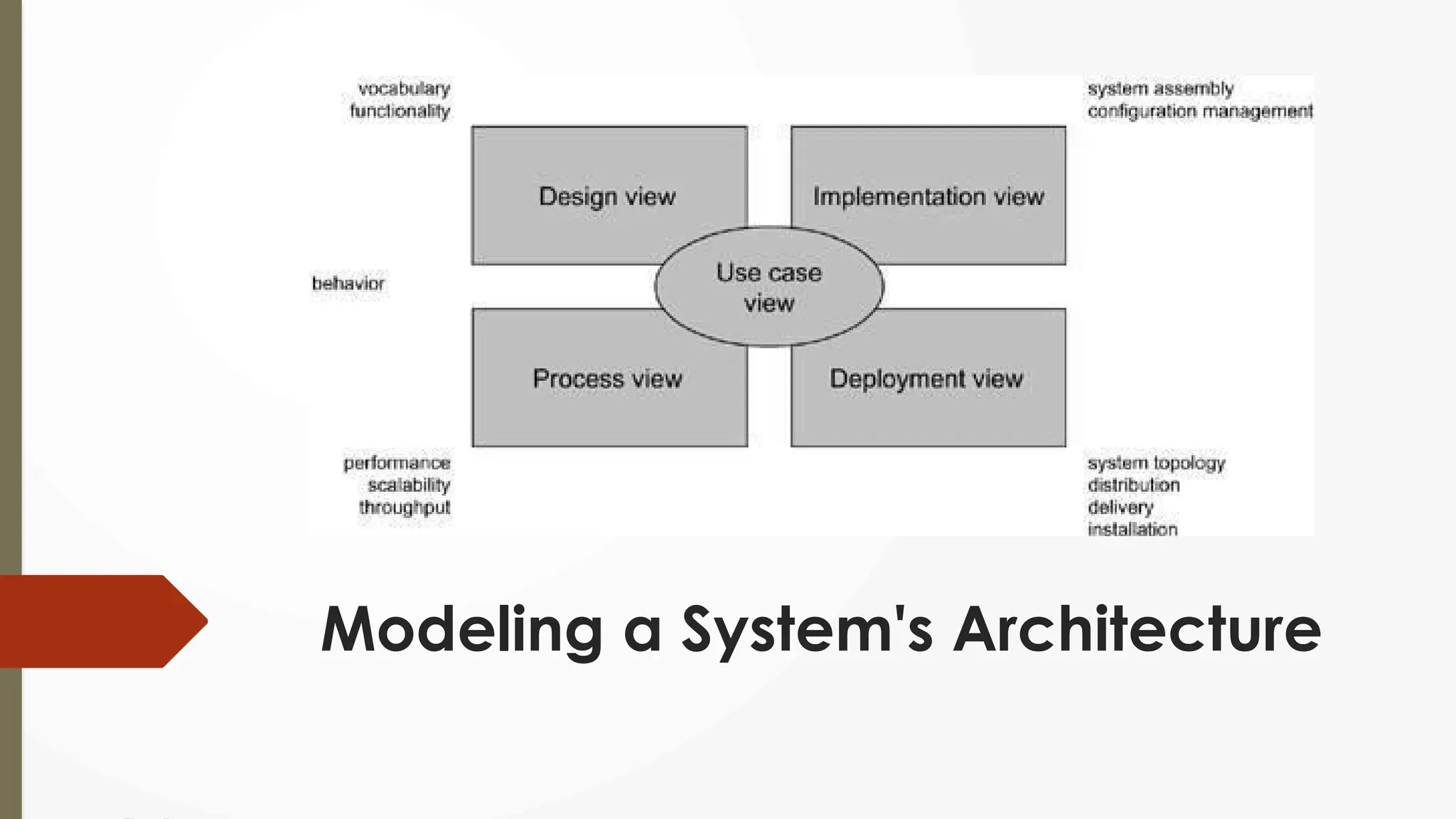
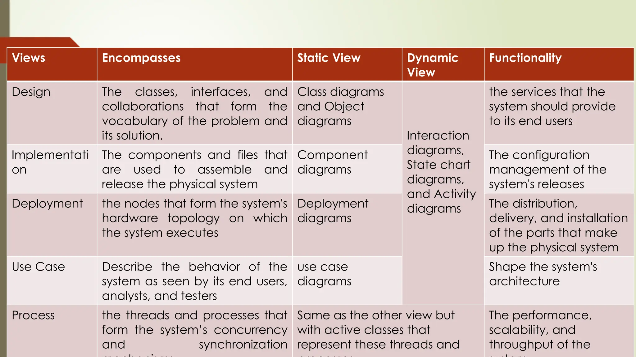
Introduction To
Unified Language Modeling
Lecturer
Sara Khurshid Siddiqui
Outline
 Importance of modeling
 Principles of modeling
 Object oriented modeling
 Conceptual model of the UML
 Architecture
 Software Development Life Cycle.
Classroom Code
 b8qlo3b
 Object Oriented Analysis and Design
Modeling
 What is Model
 A model is a simplification of reality
 Reason
 We build models so that we can better understand the system we are
developing
 Four Aims
 Visualize a system as it is or as want it to be.
 Permit to specify the structure or behavior of a system.
 Template that guides us in constructing a system.
 Document the decisions we have made.
Principles of Modeling
 First
 The choice of what models to create has a profound influence on how a
problem is attacked and how a solution is shaped.
 Second
 Every model may be expressed at different levels of precision
 Third
 The best models are connected to reality.
 Fourth
 No single model is enough. Every nontrivial system is best approached through a
small set of nearly independent models.
2 Modeling Approach
 Algorithm Approach
 Traditional view of software development.
 Main software is the procedure or function.
 Decomposition of larger algorithms into smaller ones.
 Object Orient Approach
 Modern view of software development
 Main software systems is the object or class.
 An object is a thing, drawn from the vocabulary of the problem space or the solution
space
 A class is a description of a set of common objects.
UML is a Language
 Provides a vocabulary and the rules for the
purpose of communication.
 Vocabulary and rules focus on the
conceptual and physical representation of
a system.
 Standard language for software blueprints
Visualizing
Specifying
Construction
Documentation
Conceptual Model of UML
 Three Basic Elements are required to Understand UML
 The UML's basic building blocks
 The rules that dictate how those building blocks may be put together
 Mechanisms
Building Block of UML
 The vocabulary of the UML covers three kinds of building blocks:
 Things
 Things are the abstractions that are first-class citizens in a model
 Relationships
 Tie these things together
 Diagrams
 Diagrams group interesting collections of things.
Building Block- Things
 There are four kinds of things in the UML:
 Structural things
 Behavioral things
 Grouping things
 Annotational things
These things are the basic object-oriented building blocks of the UML. You use
them to write well-formed models.
Things-Structure Things
 Nouns of UML models.
 Mostly static parts of a model
 Representing elements that are either conceptual or physical.
 7 kinds of structural things.
Things-Structure Things
1. Class
Class is a description of a set of objects that share the
same attributes, operations, relationships, and
semantics.
Things-Structure Things
2. Interface
 Collection of operations that specify a service
of a class or component.
 Represent the complete behavior of a class or
component or only a part of that behavior.
Things-Structure Things
3. Collaboration
 Interaction
 Society of roles and other elements that
work together
 A given class might participate in
several collaborations.
Things-Structure Things
4. Use Case
Description of set of sequence of
actions that a system performs that
yields an observable result of value to
a actor.
Things-Structure Thing
5. Active class
 is a class whose objects own one or
more processes or threads
 3 elements
 Heavy Line
 Components
 Nodes
 Physical Representation
Things-Structure Thing
6. Component
is a physical and replaceable
part of a system that conforms to
and provides the realization of a
set of interfaces.
Things-Structure Thing
7. Node
 Physical element that exists at run time
and represents a computational
resource
 Memory and often processing
capability.
 Migrate from node to node.
Thing- Behavioral Things
 Dynamic parts of UML models.
 Verbs of a model,
 Representing behavior over time and space.
 Two primary kinds of behavioral
Thing- Behavioral Things Types
 Interaction
 Comprises a set of messages exchanged among a set of
objects
 Individual operation may be specified with an interaction.
 involves number of other
 elements, including messages, action sequences (the
behavior invoked by a message), and links (the connection
between objects).
 State Machine
 specifies the sequences of states an object or an
interaction goes through during its lifetime in response to
events, together with its responses to those events.
 The behavior of an individual class or a collaboration of
classes may be specified with a state machine.
 involves number of other
 elements, including states, transitions (the flow from state to
state), events (things that trigger a transition), and activities
(the response to a transition).
Interaction
State Machine
Things- Grouping Things
 Grouping things are the organizational parts of
UML models.
 One Type- Packages
 Package
 Organizing elements into groups.
 Structural things, behavioral things, and even other
grouping things may be placed in a package.
 Components (which exist at run time), a package
is purely conceptual (meaning that it exists only at
development time).
 Graphically, a package is rendered as a tabbed
folder
 Usually including only its name and, sometimes, its
contents, as in shown Figure.
Things- Annotational
Thing
 the comments you may apply to
describe, illuminate, and remark about
any element in a model.
 One Type - a note.
 A note is simply a symbol for rendering
constraints and comments attached to
an element or a collection of elements.
Building
Block-
Relationship
The basic relational building
blocks of the UML.
Types of
Relationship
Dependency
Association
Generalization
Realization
Relationship – Types
 Dependency
 Semantic relationship between two things in which a change to one thing may
affect the semantics of the other thing.
 Association
 Structural relationship that describes a set of links, a link being a connection
among objects.
 Aggregation is a special kind of association, representing a structural relationship
between a whole and its part.
 Generalization
 The way in which the child shares the structure and the behavior of the parent.
 Realization
 Semantic relationship between classifiers, wherein one classifier
specifies a contract that another classifier guarantees to carry out.
 Realization relationships in two places:
 between interfaces and the classes or components that realize
them
 between use cases and the collaborations that realize them.
 One TO many
 Many to many
 Many to one
 one to one
Building
Block-
Diagrams
 Diagram is the graphical presentation of a set of
elements, most often rendered as a connected
graph of
 vertices (things) and arcs (relationships).
 the UML includes nine diagrams:
 Class diagram
 Object diagram
 Use case diagram
 Sequence diagram
 Collaboration diagram
 State chart diagram
 Activity diagram
 Component diagram
 Deployment diagram
Rules of UML
 Can't simply be thrown
together in a random
fashion.
 The development of a
software-intensive system
tend to evolve and may be
viewed by many
stakeholders in different
ways and at different times.
 Well-formed model must
follow some rules to show
model are prefect
Rules for Semantic UML Model
Name What you can call things,
relationships, and diagrams
Scope The context that gives specific
meaning to a name.
Visibility How those names can be seen and
used by others
Integrity How things properly and consistently
relate to one another
Execution What it means to run or simulate a
dynamic model
Common Mechanisms in the UML
 It is made simpler by the presence of four
common mechanisms that apply consistently
throughout the language.
 Specifications
 Adornments
 Common divisions
 Extensibility mechanisms
Common Mechanisms-Types
 Specifications
 Semantic backplane that contains all the parts/information of all the models of a system
 Each Part related to each other
 The UML's diagrams are representation of that backplane
 Each diagram revealing a specific interesting aspect of the system.
 Adornments
 Most elements in the UML have a unique and direct graphical notation that provides a
visual representation of the most important aspects of the element.
 For example, the notation for a class is intentionally designed to be easy to draw,
because classes are the most common element found in modeling object-
oriented systems. The class notation also exposes the most important aspects of a
class, namely its name, attributes, and operations.
 Every element in the UML's notation starts with a basic symbol, to which can be added
a variety of adornments specific to that symbol.
Common
Mechanisms-
Common
Divisions
In modeling object-oriented systems  gets
divided in at a couple of ways.
1st
Division of class and
object.
A class is an abstraction
An object is one concrete
manifestation of that abstraction.
2nd
Division of interface and implementation
An interface declares a
contract, and an
implementation represents one
concrete realization of that contract,
responsible for faithfully carrying out
the interface's complete semantics
Can model both class, object, interfaces and
their implementations
Common Mechanisms-Common
Divisions (Example)
Class and Object
Interface and Implementation
Common Mechanism-Extensibility
Mechanisms
 The UML's extensibility mechanisms include
 Stereotypes
 A stereotype extends the vocabulary of the UML,
allowing you to create new kinds of building blocks
that are derived from existing ones but that are
specific to your problem.
 Tagged values
 A tagged value extends the properties of a UML
building block, allowing you to create new
information in that element's specification.
 Constraints
 A constraint extends the semantics of a UML
building block, allowing you to add new rules or
modify existing ones.
Architecture
 Important artifact
 Used to manage these different viewpoints and so control
the iterative and incremental development of a system
throughout its life cycle.
 Architecture is the set of significant decisions about
 The organization of a software system
 The selection of the structural elements and their
interfaces by which the system is composed
 Their behavior, as specified in the collaborations among
those elements
 The composition of these structural and behavioral
elements into progressively larger subsystems
 The architectural style that guides this organization: the
static and dynamic elements and their interfaces, their
collaborations, and their composition
 Concerned with structure and behavior,
 Also with usage, functionality, performance, resilience,
reuse, comprehensibility, economic and technology
constraints and trade-offs, and aesthetic concerns.
Modeling a System's Architecture
Views Encompasses Static View Dynamic
View
Functionality
Design The classes, interfaces, and
collaborations that form the
vocabulary of the problem and
its solution.
Class diagrams
and Object
diagrams
Interaction
diagrams,
State chart
diagrams,
and Activity
diagrams
the services that the
system should provide
to its end users
Implementati
on
The components and files that
are used to assemble and
release the physical system
Component
diagrams
The configuration
management of the
system's releases
Deployment the nodes that form the system's
hardware topology on which
the system executes
Deployment
diagrams
The distribution,
delivery, and installation
of the parts that make
up the physical system
Use Case Describe the behavior of the
system as seen by its end users,
analysts, and testers
use case
diagrams
Shape the system's
architecture
Process the threads and processes that
form the system’s concurrency
and synchronization
Same as the other view but
with active classes that
represent these threads and
The performance,
scalability, and
throughput of the

Introduction to unified language modeling.pptx

  • 1.
    Introduction To Unified LanguageModeling Lecturer Sara Khurshid Siddiqui
  • 2.
    Outline  Importance ofmodeling  Principles of modeling  Object oriented modeling  Conceptual model of the UML  Architecture  Software Development Life Cycle.
  • 3.
    Classroom Code  b8qlo3b Object Oriented Analysis and Design
  • 4.
    Modeling  What isModel  A model is a simplification of reality  Reason  We build models so that we can better understand the system we are developing  Four Aims  Visualize a system as it is or as want it to be.  Permit to specify the structure or behavior of a system.  Template that guides us in constructing a system.  Document the decisions we have made.
  • 5.
    Principles of Modeling First  The choice of what models to create has a profound influence on how a problem is attacked and how a solution is shaped.  Second  Every model may be expressed at different levels of precision  Third  The best models are connected to reality.  Fourth  No single model is enough. Every nontrivial system is best approached through a small set of nearly independent models.
  • 6.
    2 Modeling Approach Algorithm Approach  Traditional view of software development.  Main software is the procedure or function.  Decomposition of larger algorithms into smaller ones.  Object Orient Approach  Modern view of software development  Main software systems is the object or class.  An object is a thing, drawn from the vocabulary of the problem space or the solution space  A class is a description of a set of common objects.
  • 7.
    UML is aLanguage  Provides a vocabulary and the rules for the purpose of communication.  Vocabulary and rules focus on the conceptual and physical representation of a system.  Standard language for software blueprints Visualizing Specifying Construction Documentation
  • 8.
    Conceptual Model ofUML  Three Basic Elements are required to Understand UML  The UML's basic building blocks  The rules that dictate how those building blocks may be put together  Mechanisms
  • 9.
    Building Block ofUML  The vocabulary of the UML covers three kinds of building blocks:  Things  Things are the abstractions that are first-class citizens in a model  Relationships  Tie these things together  Diagrams  Diagrams group interesting collections of things.
  • 10.
    Building Block- Things There are four kinds of things in the UML:  Structural things  Behavioral things  Grouping things  Annotational things These things are the basic object-oriented building blocks of the UML. You use them to write well-formed models.
  • 11.
    Things-Structure Things  Nounsof UML models.  Mostly static parts of a model  Representing elements that are either conceptual or physical.  7 kinds of structural things.
  • 12.
    Things-Structure Things 1. Class Classis a description of a set of objects that share the same attributes, operations, relationships, and semantics.
  • 13.
    Things-Structure Things 2. Interface Collection of operations that specify a service of a class or component.  Represent the complete behavior of a class or component or only a part of that behavior.
  • 14.
    Things-Structure Things 3. Collaboration Interaction  Society of roles and other elements that work together  A given class might participate in several collaborations.
  • 15.
    Things-Structure Things 4. UseCase Description of set of sequence of actions that a system performs that yields an observable result of value to a actor.
  • 16.
    Things-Structure Thing 5. Activeclass  is a class whose objects own one or more processes or threads  3 elements  Heavy Line  Components  Nodes  Physical Representation
  • 17.
    Things-Structure Thing 6. Component isa physical and replaceable part of a system that conforms to and provides the realization of a set of interfaces.
  • 18.
    Things-Structure Thing 7. Node Physical element that exists at run time and represents a computational resource  Memory and often processing capability.  Migrate from node to node.
  • 19.
    Thing- Behavioral Things Dynamic parts of UML models.  Verbs of a model,  Representing behavior over time and space.  Two primary kinds of behavioral
  • 20.
    Thing- Behavioral ThingsTypes  Interaction  Comprises a set of messages exchanged among a set of objects  Individual operation may be specified with an interaction.  involves number of other  elements, including messages, action sequences (the behavior invoked by a message), and links (the connection between objects).  State Machine  specifies the sequences of states an object or an interaction goes through during its lifetime in response to events, together with its responses to those events.  The behavior of an individual class or a collaboration of classes may be specified with a state machine.  involves number of other  elements, including states, transitions (the flow from state to state), events (things that trigger a transition), and activities (the response to a transition). Interaction State Machine
  • 21.
    Things- Grouping Things Grouping things are the organizational parts of UML models.  One Type- Packages  Package  Organizing elements into groups.  Structural things, behavioral things, and even other grouping things may be placed in a package.  Components (which exist at run time), a package is purely conceptual (meaning that it exists only at development time).  Graphically, a package is rendered as a tabbed folder  Usually including only its name and, sometimes, its contents, as in shown Figure.
  • 22.
    Things- Annotational Thing  thecomments you may apply to describe, illuminate, and remark about any element in a model.  One Type - a note.  A note is simply a symbol for rendering constraints and comments attached to an element or a collection of elements.
  • 23.
    Building Block- Relationship The basic relationalbuilding blocks of the UML. Types of Relationship Dependency Association Generalization Realization
  • 24.
    Relationship – Types Dependency  Semantic relationship between two things in which a change to one thing may affect the semantics of the other thing.  Association  Structural relationship that describes a set of links, a link being a connection among objects.  Aggregation is a special kind of association, representing a structural relationship between a whole and its part.  Generalization  The way in which the child shares the structure and the behavior of the parent.  Realization  Semantic relationship between classifiers, wherein one classifier specifies a contract that another classifier guarantees to carry out.  Realization relationships in two places:  between interfaces and the classes or components that realize them  between use cases and the collaborations that realize them.
  • 25.
     One TOmany  Many to many  Many to one  one to one
  • 26.
    Building Block- Diagrams  Diagram isthe graphical presentation of a set of elements, most often rendered as a connected graph of  vertices (things) and arcs (relationships).  the UML includes nine diagrams:  Class diagram  Object diagram  Use case diagram  Sequence diagram  Collaboration diagram  State chart diagram  Activity diagram  Component diagram  Deployment diagram
  • 27.
    Rules of UML Can't simply be thrown together in a random fashion.  The development of a software-intensive system tend to evolve and may be viewed by many stakeholders in different ways and at different times.  Well-formed model must follow some rules to show model are prefect Rules for Semantic UML Model Name What you can call things, relationships, and diagrams Scope The context that gives specific meaning to a name. Visibility How those names can be seen and used by others Integrity How things properly and consistently relate to one another Execution What it means to run or simulate a dynamic model
  • 28.
    Common Mechanisms inthe UML  It is made simpler by the presence of four common mechanisms that apply consistently throughout the language.  Specifications  Adornments  Common divisions  Extensibility mechanisms
  • 29.
    Common Mechanisms-Types  Specifications Semantic backplane that contains all the parts/information of all the models of a system  Each Part related to each other  The UML's diagrams are representation of that backplane  Each diagram revealing a specific interesting aspect of the system.  Adornments  Most elements in the UML have a unique and direct graphical notation that provides a visual representation of the most important aspects of the element.  For example, the notation for a class is intentionally designed to be easy to draw, because classes are the most common element found in modeling object- oriented systems. The class notation also exposes the most important aspects of a class, namely its name, attributes, and operations.  Every element in the UML's notation starts with a basic symbol, to which can be added a variety of adornments specific to that symbol.
  • 30.
    Common Mechanisms- Common Divisions In modeling object-orientedsystems  gets divided in at a couple of ways. 1st Division of class and object. A class is an abstraction An object is one concrete manifestation of that abstraction. 2nd Division of interface and implementation An interface declares a contract, and an implementation represents one concrete realization of that contract, responsible for faithfully carrying out the interface's complete semantics Can model both class, object, interfaces and their implementations
  • 31.
    Common Mechanisms-Common Divisions (Example) Classand Object Interface and Implementation
  • 32.
    Common Mechanism-Extensibility Mechanisms  TheUML's extensibility mechanisms include  Stereotypes  A stereotype extends the vocabulary of the UML, allowing you to create new kinds of building blocks that are derived from existing ones but that are specific to your problem.  Tagged values  A tagged value extends the properties of a UML building block, allowing you to create new information in that element's specification.  Constraints  A constraint extends the semantics of a UML building block, allowing you to add new rules or modify existing ones.
  • 33.
    Architecture  Important artifact Used to manage these different viewpoints and so control the iterative and incremental development of a system throughout its life cycle.  Architecture is the set of significant decisions about  The organization of a software system  The selection of the structural elements and their interfaces by which the system is composed  Their behavior, as specified in the collaborations among those elements  The composition of these structural and behavioral elements into progressively larger subsystems  The architectural style that guides this organization: the static and dynamic elements and their interfaces, their collaborations, and their composition  Concerned with structure and behavior,  Also with usage, functionality, performance, resilience, reuse, comprehensibility, economic and technology constraints and trade-offs, and aesthetic concerns.
  • 34.
    Modeling a System'sArchitecture
  • 35.
    Views Encompasses StaticView Dynamic View Functionality Design The classes, interfaces, and collaborations that form the vocabulary of the problem and its solution. Class diagrams and Object diagrams Interaction diagrams, State chart diagrams, and Activity diagrams the services that the system should provide to its end users Implementati on The components and files that are used to assemble and release the physical system Component diagrams The configuration management of the system's releases Deployment the nodes that form the system's hardware topology on which the system executes Deployment diagrams The distribution, delivery, and installation of the parts that make up the physical system Use Case Describe the behavior of the system as seen by its end users, analysts, and testers use case diagrams Shape the system's architecture Process the threads and processes that form the system’s concurrency and synchronization Same as the other view but with active classes that represent these threads and The performance, scalability, and throughput of the

Editor's Notes

  • #35  made up of independent components and files that can be assembled in various ways to produce a running system.