Downloaded 814 times

![Table 1 Climatic conditions for operation (Cont.)
Property Value
Telcordia GR-63-CORE, Vibrational requirements for
earthquake Zone 2
Max. 9 modules in pile, maximum total height 22 U
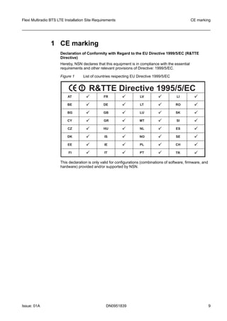
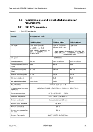
Table 2 Temperature and humidity values
Property Temperature Humidity, relative
Transportation -40°C - +70°C (-40°F - +158°F) Max. 95%
Storage -33°C - +40°C (-27.4°F - +104°F) 15 - 100%
High ambient air temperature
limit
+55°C (+131°F) in shade with guar-
anteed minimum performance of
3GPP specification
+50°C (+122°F) in shade with guar-
anteed performance (that is better
than 3GPP)
+50°C (+122°F) in direct sunlight
with guaranteed minimum perfor-
mance of 3GPP specification
+45°C (+113°F) in direct sunlight
with guaranteed performance (that
is better than 3GPP)
15 - 100%
Operational -35°C - +55°C (-31°F - +131°F) ~95%
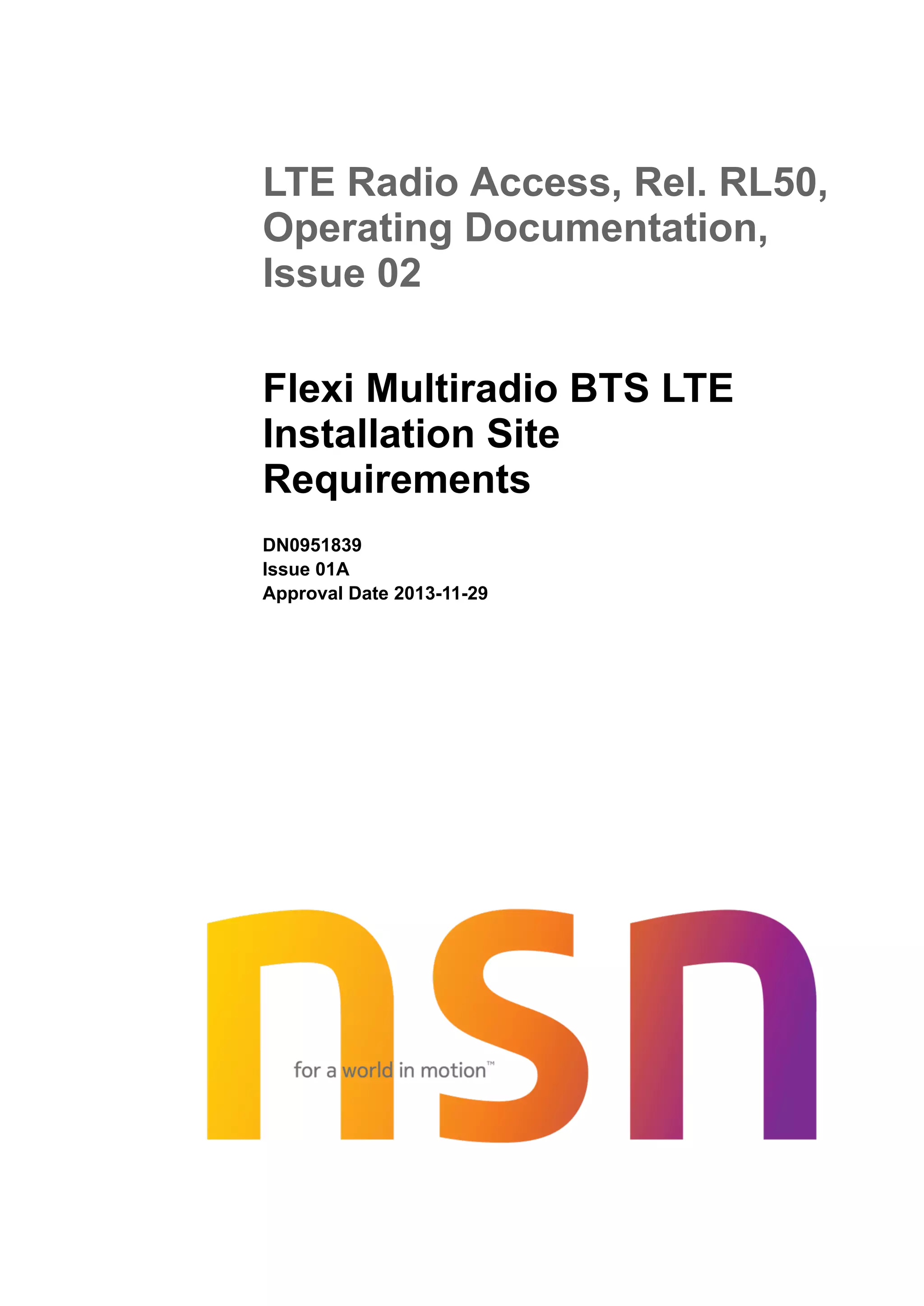
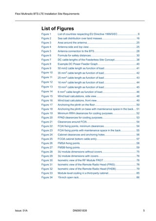
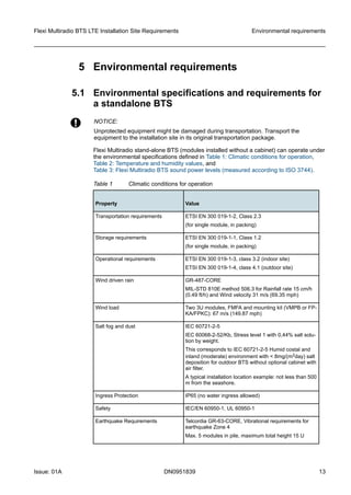
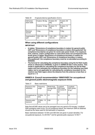
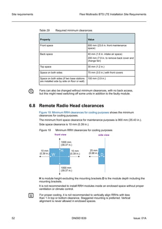
Table 3: Flexi Multiradio BTS sound power levels (measured according to ISO 3744)
shows the sound power levels measured with linear curve control.
Table 3 Flexi Multiradio BTS sound power levels (measured according to ISO
3744)
Configuration Minimum
[dBA]
(15°C (59°F),
10% RF load)
Typical [dBA]
(23°C (73.4°F),
50% RF load)
Max [dBA]
(40°C (104°F),
100% RF load)
Max [dBA]
(50°C (122°F),
100% RF load)
1+1+1@ 20 W
System Module with one
3-sector RF Module
Max. 51 Max. 54 Max. 60 Max. 65
1+1+1@ 40 W
System Module with one
3-sector RF Module
Max. 54 Max. 56 Max. 62 Max. 66
2+2+2@ 40 W Max. 57 Max. 59 Max. 66 Max. 69
Environmental requirements Flexi Multiradio BTS LTE Installation Site Requirements
14 DN0951839 Issue: 01A](https://image.slidesharecdn.com/fleximultiradiobtslteinstallationsiterequirements-160323091037/85/Flexi-multiradio-bts-lte-installation-site-requirements-14-320.jpg)
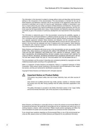
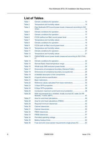
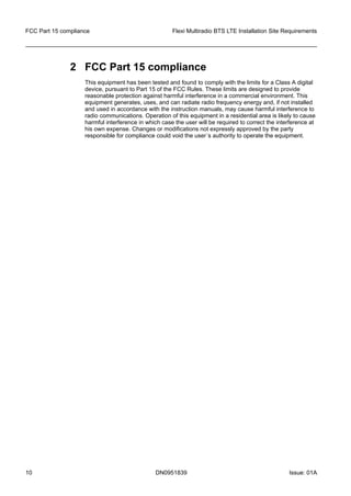
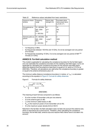
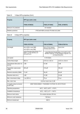
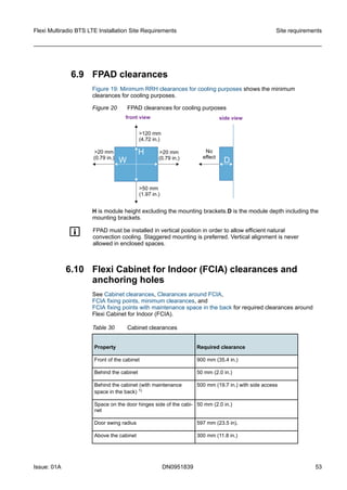
![Table 3 Flexi Multiradio BTS sound power levels (measured according to ISO
3744) (Cont.)
Configuration Minimum
[dBA]
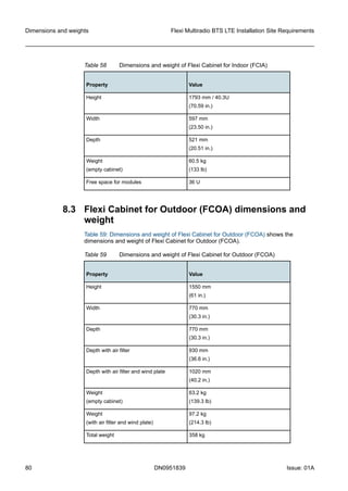
(15°C (59°F),
10% RF load)
Typical [dBA]
(23°C (73.4°F),
50% RF load)
Max [dBA]
(40°C (104°F),
100% RF load)
Max [dBA]
(50°C (122°F),
100% RF load)
System Module and two
RF Modules
FPMA effect
Add to above values:
Max. 3 Max. 3 Max. 3 Max. 3
For the sound power of a 3-sector RF Module alone, see the values for a 1+1+1@ 20 W config-
uration.
For the sound power of a System Module alone, subtract 3 dBA from the above values.
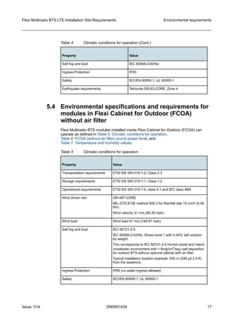
5.2 Installations with cabinet
Modules must be installed in an indoor cabinet or an outdoor cabinet, when:
• more than nine modules are installed in a stack (total height over 22 U*)
• more than five modules are installed in a stack (total height over 15 U) and the
Telcordia GR-63-CORE Zone 4 requirement is still met
• the BTS is installed in a separate locked space
• cabinet can be also used as one option to make locked space
g 22 U high stack meets Telcordia GR-63-CORE Zone 2 earthquake requirement.
An air filter must be used together with the BTS cabinet when standard-based
operational environmental conditions presented in
Environmental specifications and requirements for a stand-alone BTS are exceeded.
Typically, a cabinet with an optional air filter is needed:
• in places where dust is a concern
• next to a dusty road with heavy traffic
• in sandy terrain with the possibility of wind-blown sand in the air
• next to an industrial plant with significant emissions of dust or other particles, such as
cement factory, sawmill, and so on
• nearby a cornfield with heavy straw dust during harvesting
• in places where salt fog or acid rain caused by air pollution is a concern
• in site locations where surrounding metal structures show signs of corrosion because
of the extreme conditions (salt in air)
• in locations with especially heavy rainfall and high humidity combined with air
pollution
• near sea shore:
– with dense salt fog because of the breaking waves
– with dense salt fog and line of sight to the sea (not behind a large building)
– where wind-driven salt fog from sea can be identified
Flexi Multiradio BTS LTE Installation Site Requirements Environmental requirements
Issue: 01A DN0951839 15](https://image.slidesharecdn.com/fleximultiradiobtslteinstallationsiterequirements-160323091037/85/Flexi-multiradio-bts-lte-installation-site-requirements-15-320.jpg)

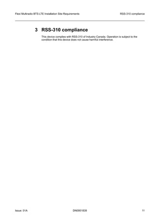
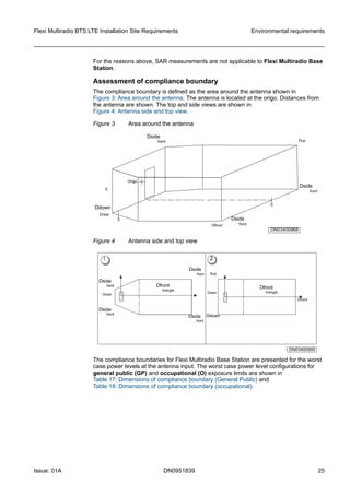
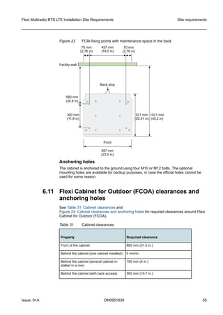
![Table 5 Climatic conditions for operation (Cont.)
Property Value
Earthquake requirements Telcordia GR-63-CORE, Zone 4
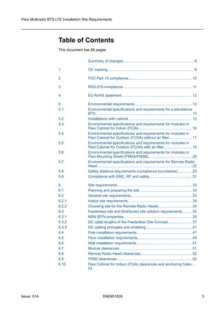
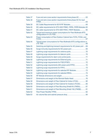
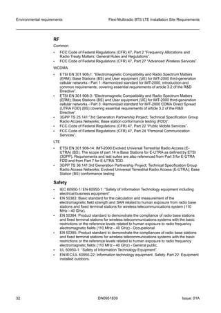
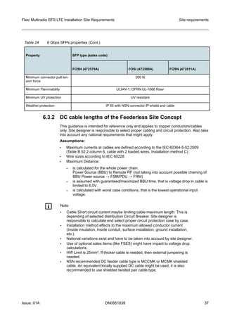
Table 6: FCOA (without air filter) sound power level shows the sound power levels
measured with linear curve control.
Table 6 FCOA (without air filter) sound power level
Value Configuration Max [dBA]
Sound power, night time
(in +15°C (59°F), 10% RF load,
ISO3744)
1+1+1 40W/carrier
(System Module with one 3-sector RF
Module)
55
Sound power, day time
(in +23°C (73.4°F), 50% RF load,
ISO3744)
1+1+1 40W/carrier
(System Module with one 3-sector RF
Module)
57
Sound power, extreme
(in +40°C (104°F), 100% RF load,
ISO3744)
1+1+1 40W/carrier
(System Module with one 3-sector RF
Module)
63
Table 7 Temperature and humidity values
Property Temperature Humidity, relative%
Transportation -40°C - +70°C (-40°F - +158°F) Max. 95%
Storage -33°C - +40°C (-27.4°F - +104°F) 15 - 100%
High ambient air
temperature limit
+55°C (+131°F) in shade with guaranteed
minimum performance of 3GPP specification
+50°C (+122°F) in shade with guaranteed
performance (that is better than 3GPP)
+50°C (+122°F) in direct sunlight with guaran-
teed minimum performance of 3GPP specifi-
cation
+45°C (+113°F) in direct sunlight with guaran-
teed performance (that is better than 3GPP)
15 - 100%
Operational -35°C - +55°C (-31°F - +131°F) ~95%
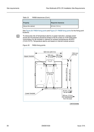
g To reduce the risk of temperature alarms or power reduction, average power
across all TX branches should be limited to 60 W or less (or 4 kW total power
consumption for all modules in cabinet) for ambient temperatures 46-55ºC
(114.8-131ºF). Temperature alarms are based on internal module sensors.
Environmental requirements Flexi Multiradio BTS LTE Installation Site Requirements
18 DN0951839 Issue: 01A](https://image.slidesharecdn.com/fleximultiradiobtslteinstallationsiterequirements-160323091037/85/Flexi-multiradio-bts-lte-installation-site-requirements-18-320.jpg)
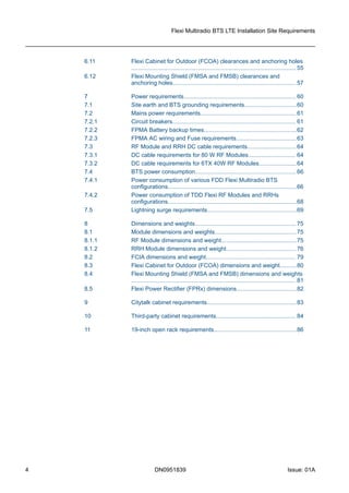
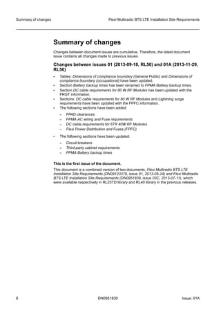
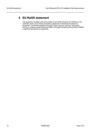
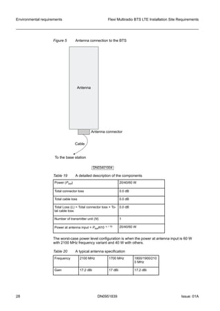
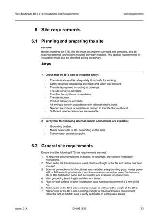
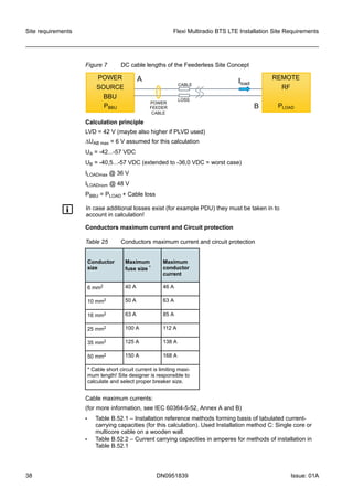
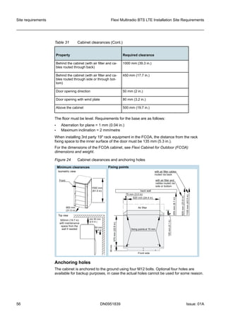
![5.5 Environmental specifications and requirements for
modules in Flexi Cabinet for Outdoor (FCOA) with
air filter
Flexi Multiradio BTS modules installed inside Flexi Cabinet for Outdoor (FCOA) with an
optional air filter can operate as defined in Table 8: Climatic conditions for operation,
Table 9: FCOA (with air filter) sound power level, and
Table 10: Temperature and humidity values.
Table 8 Climatic conditions for operation
Property Value
Transportation requirements ETSI EN 300 019-1-2, Class 2.3
Storage requirements ETSI EN 300 019-1-1, Class 1.3
Operational requirements ETSI EN 300 019-1-4, class 4.1 and IEC class 4M5
Wind driven rain GR-487-CORE
MIL-STD 810E method 506.3 for rainfall rate 15cm/h ()0.49
ft/h
Wind velocity 31 m/s (69.35 mph)
Wind load Wind load 67 m/s (149.87 mph)
Salt fog and dust IEC 60721-2-5
IEC 60068-2-52/Kb, Stress level 1 with 5% salt solution by
weight
This corresponds to IEC 60721-2-5 oceanic and coastal en-
vironment with > 8mg/(m2day) salt deposition for outdoor
BTS with optional air filter.
When installing a cabinet with an air filter on a seashore, it is recommended that the cabinet is
installed with the side wall facing the sea (not the filter or the door).
Ingress Protection IP65 (no water ingress allowed)
Safety IEC/EN 60950-1, UL 60950-1
Earthquake requirements Telcordia GR-63-CORE, Zone 4
Table 9: FCOA (with air filter) sound power level shows the sound power levels
measured with linear curve control.
Table 9 FCOA (with air filter) sound power level
Value Configuration Max [dBA]
Sound power, night time 1+1+1 40W/carrier 56*
Flexi Multiradio BTS LTE Installation Site Requirements Environmental requirements
Issue: 01A DN0951839 19](https://image.slidesharecdn.com/fleximultiradiobtslteinstallationsiterequirements-160323091037/85/Flexi-multiradio-bts-lte-installation-site-requirements-19-320.jpg)
![Table 9 FCOA (with air filter) sound power level (Cont.)
Value Configuration Max [dBA]
(in +15°C (59°F), 10% RF load,
ISO3744)
(System Module with one 3-sector
RF Module)
Sound power, day time
(in +23°C (73.4°F), 50% RF load,
ISO3744)
1+1+1 40W/carrier
(System Module with one 3-sector
RF Module)
59*
Sound power, extreme
(in +40°C (104°F), 100% RF load,
ISO3744)
1+1+1 40W/carrier
(System Module with one 3-sector
RF Module)
65*
*) Sound power figures measured with a clean filter.
Table 10 Temperature and humidity values
Property Temperature Humidity, relative%
Transportation -40°C - +70°C (-40°F - +158°F) Max. 95%
Storage -33°C - +40°C (-27.4°F - +104°F) 15 - 100%
High ambient air
temperature limit
+55°C (+131°F) in shade with guaranteed min-
imum performance of 3GPP specification
+50°C (+122°F) in shade with guaranteed per-
formance (that is better than 3GPP)
+50°C (+122°F) in direct sunlight with guaran-
teed minimum performance of 3GPP specifi-
cation
+45°C (+113°F) in direct sunlight with guaran-
teed performance (that is better than 3GPP)
15 - 100%
Operational -35°C - +55°C (-31°F - +131°F) ~95%
g To reduce the risk of temperature alarms or power reduction, average power
across all TX branches should be limited to 60 W or less (or 4 kW total power
consumption for all modules in cabinet) for ambient temperatures 46-55ºC
(114.8-131ºF). Temperature alarms are based on internal module sensors.
5.6 Environmental specifications and requirements for
modules in Flexi Mounting Shield (FMSA/FMSB)
Flexi Multiradio BTS modules installed inside Flexi Mounting Shield (FMSA/FMSB)
cabinet can operate in the climatic conditions as defined in
Table 11: Climatic conditions for operation.
Environmental requirements Flexi Multiradio BTS LTE Installation Site Requirements
20 DN0951839 Issue: 01A](https://image.slidesharecdn.com/fleximultiradiobtslteinstallationsiterequirements-160323091037/85/Flexi-multiradio-bts-lte-installation-site-requirements-20-320.jpg)
![Table 11 Climatic conditions for operation
Property Value
Operational requirements ETSI EN 300 019-1-4, class 4.1 and IEC class 4M5
Wind driven rain GR-487-CORE
Wind velocity 31 m/s (69.36 mph)
Wind load Wind load 67 m/s (149.87 mph)
Ingress Protection IP65 (no water ingress allowed)
Safety IEC 60529
Earthquake requirements Telcordia GR-63-CORE, Zone 4*
*If a sixth module is installed in the cabinet, the earthquake requirements are according to
Zone 2.
In extreme conditions, for example, with high salinity less than 500 m to the sea or high
dust density in the air, it is required to use a shelter or outdoor cabinet with an air filter.
Table 12 Temperature and humidity values
Property Temperature Humidity, relative%
Transportation -40°C - +70°C (-40°F - +158°F) Max. 95%
Storage -33°C - +40°C (-27.4°F - +104°F) 15 - 100%
Operational -35°C - +55°C (-31°F - +131°F) ~95%
Table 13: FMSA/FMSB sound power levels (measured according to ISO 3744) shows
the sound power levels measured with linear curve control.
Table 13 FMSA/FMSB sound power levels (measured according to ISO 3744)
Configuration Minimum
[dBA]
(in 15°C
(59°F), 10%
RF load)
Typical [dBA]
(in 23°C
(73.4°F), 50%
RF load)
Max [dBA]
(in 40°C
(104°F),
100% RF
load)
Max [dBA]
(in 50°C
(122°F),
100% RF
load)
1+1+1 @ 20W
(System Module one 3-sector
RF Module)
Max. 51 Max. 54 Max. 60 Max. 65
1+1+1 @ 40W
(System Module with one 3-
sector RF Module)
Max. 54 Max. 56 Max. 62 Max. 66
2+2+2 @ 40W Max. 57 Max. 59 Max. 66 Max. 69
Flexi Multiradio BTS LTE Installation Site Requirements Environmental requirements
Issue: 01A DN0951839 21](https://image.slidesharecdn.com/fleximultiradiobtslteinstallationsiterequirements-160323091037/85/Flexi-multiradio-bts-lte-installation-site-requirements-21-320.jpg)
![Table 13 FMSA/FMSB sound power levels (measured according to ISO 3744)
(Cont.)
Configuration Minimum
[dBA]
(in 15°C
(59°F), 10%
RF load)
Typical [dBA]
(in 23°C
(73.4°F), 50%
RF load)
Max [dBA]
(in 40°C
(104°F),
100% RF
load)
Max [dBA]
(in 50°C
(122°F),
100% RF
load)
(System Module and two RF
Modules)
FPMA effect
Add to above values:
Max. 3 Max. 3 Max. 3 Max. 3
5.7 Environmental specifications and requirements for
Remote Radio Head
w NOTICE:
Unprotected equipment might be damaged during transportation. Transport the
equipment to the installation site in its original transportation package.
Table 14 Climatic conditions for operation
Property Value
Transportation requirements ETSI EN 300 019-1-2, Class 2.3
Storage requirements ETSI EN 300 019-1-1, Class 1.2
Operational requirements ETSI EN 300 019-1-4, class 4.1 and IEC class
4M5
Wind driven rain GR-487-CORE
MIL-STD 810E method 506.3 for Rainfall rate 15
cm/hr.
Wind velocity 31 m/s
Wind load Mounting kit (VMPB or FPKA/FPKC) included: 67
m/s
Salt fog and dust IEC 60721-2-5
IEC 60068-2-52/Kb, Stress level 1 with 0,44% salt
solution by weight.
This corresponds to IEC 60721-2-5 Humid costal
and inland (moderate) environment with <
8mg/(m2day) salt deposition for outdoor BTS with-
out optional cabinet with air filter.
Typical installation location example: 500 m from
the seashore.
Environmental requirements Flexi Multiradio BTS LTE Installation Site Requirements
22 DN0951839 Issue: 01A](https://image.slidesharecdn.com/fleximultiradiobtslteinstallationsiterequirements-160323091037/85/Flexi-multiradio-bts-lte-installation-site-requirements-22-320.jpg)

![Installing base stations to ensure installer safety
Installation engineers need to be aware of the potential risk of the thermal effects of radio
frequency energy and how to protect themselves against undue risk. The information
shown in the Warnings and cautions provided section is taken from the relevant section
of NSN product documentation containing warnings and cautions specific to the
equipment.
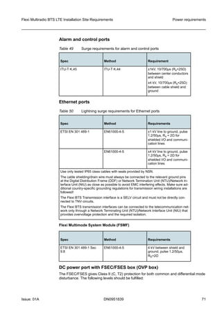
Warnings and cautions provided
Reference safety distances
When working close to transmitter antennas, the proper safety distances must be
observed. The minimum safe distance from an antenna is measured in metres.
f The antenna generates electromagnetic fields at radio frequencies. Do not
cross the compliance boundary.
f This equipment generates electromagnetic fields. If performing installation or
maintenance procedures on the antenna systems, make sure that all the
transmitters in the area are switched off.
When assessing the applicable boundaries, the European standards EN 50383, EN
50384, EN 50385 and Council Recommendation 1999/519/EC for occupational and
general public electromagnetic exposure limits - see Annex A - have been applied.
The statements shown below are taken from the NSN product documentation containing
warning and cautions specific to the equipment.
Assessment applying Specific Absorption Rate (SAR)
measurements
European standards EN 50383, EN 50384 and EN 50385 do not include specifications
for whole body SAR measurements. Whole body SAR measurements are not required
for transmitters that have maximum output power levels too low to result in exposure
levels that can reach the whole body SAR compliance limits under any conditions. Whole
body SAR exclusion power levels have been based on the worst case assumptions. For
details, see Table 16: Whole body SAR exclusion power levels.
Table 16 Whole body SAR exclusion power levels
Exposure category Maximum output power (rms)
General public Max power [W] = general public whole
body SAR limit [W/kg] * 12.5 kg: 4-year-
old child body mass = 1 W
Occupational Max power [W] = occupational whole body
SAR limit [W/kg] * 42 kg: 16-year-old
worker body mass = 16.8 W
Localized SAR measurements can only be used when:
1. The separation between the phantom and the outer surface of the energy generating
element is 40 cm (15.6 in.) or less.
2. The surface area of the energy generating element is less than 60 cm (23.6 in.) by
30 cm (11.8 in.).
3. The frequency is in the range of 800 to 3000 MHz.
Environmental requirements Flexi Multiradio BTS LTE Installation Site Requirements
24 DN0951839 Issue: 01A](https://image.slidesharecdn.com/fleximultiradiobtslteinstallationsiterequirements-160323091037/85/Flexi-multiradio-bts-lte-installation-site-requirements-24-320.jpg)
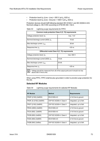
![Table 17 Dimensions of compliance boundary (General Public)
Dfront
[m]
Dfront
triangle
[m]
Drear
[m]
Dside
back
[m]
Dside
front
[m]
Dup
[m]
Ddown
[m]
Freq. (MHz) Power
at an-
tenna
input
GP GP GP GP GP GP GP
900 40 7 2.4 0.3 0.4 2 0.95 0.95
1700 40 4.4 1.2 0.1 0.2 1.5 0.6 0.6
1700 2 * 60 7.7 2.4 0.1 0.7 3.0 0.8 1.8
1800 40 4.4 1.2 0.1 0.2 1.5 0.5 0.5
1900 80 6.45 1.5 0.25 0.4 2.05 0.6 0.6
2100 40 4.7 1.5 0.1 0.4 1.5 0.6 0.6
2100 60 5.7 2.0 0.1 0.5 1.85 1.6 1.0
2100 80 6.45 1.5 0.25 0.4 2.05 0.6 0.6
2100 2 * 60 7.8 3.0 0.1 0.8 2.8 2.1 1.4
2300 - 2600 8 0.85 0.25 0.1 0.15 0.15 0.7 0.7
2300 - 2600 20 2.7 0.75 0.1 0.25 0.65 1.1 0.8
2300 - 2600 40 4.5 1.6 0.1 0.4 1.4 1.45 1.1
2300 - 2600 60 5.8 1.8 0.1 0.5 2 1.7 1.25
Recommend 2-200 m (6.56- 656.17 ft.)
Table 18 Dimensions of compliance boundary (occupational)
Dfront
[m]
Dfront
triangle
[m]
Drear
[m]
Dside
back
[m]
Dside
front
[m]
Dup
[m]
Ddown
[m]
Freq. (MHz) Power
at an-
tenna
input
O O O O O O O
900 40 2.95 1 0.05 0.2 0.6 0.85 0.85
1700 40 1.9 1.1 0.1 0.2 0.45 0.48 0.48
1700 2 * 60 2.6 0.8 0.1 0.2 0.7 0.7 0.75
Environmental requirements Flexi Multiradio BTS LTE Installation Site Requirements
26 DN0951839 Issue: 01A](https://image.slidesharecdn.com/fleximultiradiobtslteinstallationsiterequirements-160323091037/85/Flexi-multiradio-bts-lte-installation-site-requirements-26-320.jpg)
![Table 18 Dimensions of compliance boundary (occupational) (Cont.)
Dfront
[m]
Dfront
triangle
[m]
Drear
[m]
Dside
back
[m]
Dside
front
[m]
Dup
[m]
Ddown
[m]
1800 40 2.1 1.1 0.1 0.2 0.65 0.45 0.45
1900 80 3 1.1 0.15 0.2 0.95 0.5 0.5
2100 40 1.95 0.7 0.1 0.25 0.5 0.6 0.6
2100 60 1.1 0.4 0.1 0.1 0.3 1.0 1.0
2100 80 3 1.1 0.15 0.2 0.95 0.5 0.5
2100 2 * 60 1.8 0.6 0.1 0.2 0.55 0.9 0.7
2300 - 2600 8 0.15 0.1 0.1 0.1 0.1 0.7 0.7
2300 - 2600 20 0.35 0.1 0.1 0.1 0.15 0.7 0.7
2300 - 2600 40 0.85 0.2 0.1 0.15 0.25 0.7 0.7
2300 - 2600 60 1.4 0.3 0.1 0.15 0.35 0.75 0.7
Recommend 2-200 m (6.56- 656.17 ft.)
The component specifications for 900 MHz and 1800 MHz also apply to 850 MHz and
1900 MHz products, respectively, and can be used to demonstrate compliance with FCC
guidelines for human exposure to radio frequency electromagnetic fields contained in the
FCC document OET Bulletin 65 (August 1997).
Typical configuration
The antenna is connected through a connector and cable(s) to the base station as
shown in Figure 5: Antenna connection to the BTS.
Flexi Multiradio BTS LTE Installation Site Requirements Environmental requirements
Issue: 01A DN0951839 27](https://image.slidesharecdn.com/fleximultiradiobtslteinstallationsiterequirements-160323091037/85/Flexi-multiradio-bts-lte-installation-site-requirements-27-320.jpg)


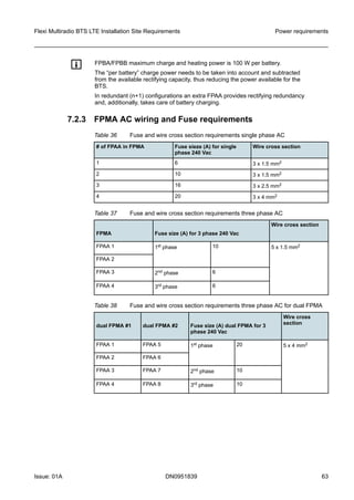
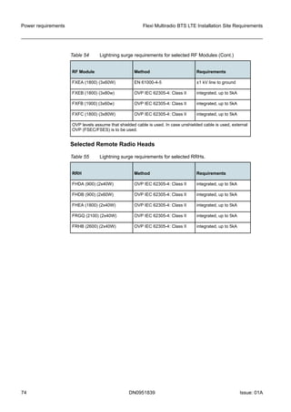
![7.2.2 FPMA Battery backup times
Flexi BTS uses 48 VDC power. In a BTS site with AC feed only, Flexi Power Module
(FPMA) is required to convert AC to DC. Flexi Power Module (FPMA) consists of
mechanics, AC terminal, and four slots for AC/DC sub-module (FPAA) or battery sub-
module (FPBA/B).
Two FPMAs can be installed in a stack to support FPAA and FPBA/B operating in
parallel.
Table 35: Battery backup times shows the battery backup times depending on
configuration and load scenario.
Table 35 Battery backup times
FPMA Estimated typical battery backup time in 23°C for new battery [min.]
Single FPMA Dual FPMA (stacked)
Rectifying
capacity [W]
FPAA
(rectifier)
1 x FPBA/B
(battery)
2 x FPBA/B
(battery)
3 x FPBA/B
(battery)
4 x FPBA/B
(battery)
5 x FPBA/B
(battery)
6 x FPBA/B
(battery)
250 1 32 64 96 128 160 192
500 1 16 32 48 64 80 96
750 1 11 22 33 44 55 66
1000 1 8 16 24 32 40 48
1250 2 - 13 19 26 32 38
1500 2 - 11 16 21 27 32
1750 2 - 9 14 18 23 27
2000 2 - 8 12 16 20 24
2250 3 - - 11 14 18 -
2500 3 - - 10 13 16 -
2750 3 - - 9 12 15 -
3000 3 - - 8 11 13 -
3250 4 - - - 10 - -
3500 4 - - - 9 - -
3750 4 - - - 9 - -
4000 4 - - - 8 - -
Power requirements Flexi Multiradio BTS LTE Installation Site Requirements
62 DN0951839 Issue: 01A](https://image.slidesharecdn.com/fleximultiradiobtslteinstallationsiterequirements-160323091037/85/Flexi-multiradio-bts-lte-installation-site-requirements-62-320.jpg)
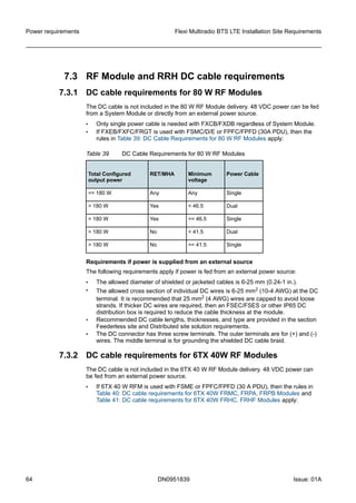
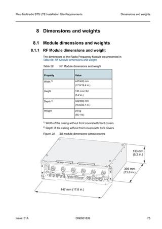
![7.4 BTS power consumption
7.4.1 Power consumption of various FDD Flexi Multiradio BTS
configurations
See
Table 42: Typical and maximum power consumptions for Flexi Multiradio BTS
configurations in LTE FDD for Flexi Multiradio BTS power consumption values at 48 VDC
input in 23°C.
For the FSME system module with FTIB transmission sub-module, add 110 W to
the given values.
For the alternative transmission sub-module FTLB, add 25 W in addition to the
given values.
Table 42 Typical and maximum power consumptions for Flexi Multiradio BTS
configurations in LTE FDD
Configuration RF output
power per
sector
[W]
Estimated typical power
consumption [W] at 48 VDC
input in 23 °C
50% RF load 100% RF
load
1+1+1 SIMO 1TX 2RX 2600MHz
FSMF + 3-sector RF Module
60 931 1255
1+1+1 SIMO 1TX 2RX 1800MHz
FSMF + 3-sector RF Module
60 804 1034
1+1+1 SIMO 1TX 2RX 1800MHz
FSMF + 3-sector RF Module
80 809 1183
1+1+1 SIMO 1TX 2RX 800MHz
FSMF + 3-sector RF Module
60 794 1068
1+1+1 MIMO 2TX 2RX 2600MHz
FSMF + 3-sector RF Module
60+60 1737 2385
1+1+1 MIMO 2TX 2RX 1800MHz
FSMF + 3-sector RF Module
60+60 1483 1943
1+1+1 MIMO 2TX 2RX 1800MHz
FSMF + 3-sector RF Module
80+80 1493 2241
1+1+1 MIMO 2TX 2RX 800MHz
FSMF + 3-sector RF Module
60+60 1463 2011
1+1+1 MIMO 2TX 2RX 2600MHz
FSMF + 2TX RRH Module
40+40 1076 1442
Power requirements Flexi Multiradio BTS LTE Installation Site Requirements
66 DN0951839 Issue: 01A](https://image.slidesharecdn.com/fleximultiradiobtslteinstallationsiterequirements-160323091037/85/Flexi-multiradio-bts-lte-installation-site-requirements-66-320.jpg)
![Table 42 Typical and maximum power consumptions for Flexi Multiradio BTS
configurations in LTE FDD (Cont.)
Configuration RF output
power per
sector
[W]
Estimated typical power
consumption [W] at 48 VDC
input in 23 °C
50% RF load 100% RF
load
1+1+1 MIMO 2TX 2RX 1800MHz
FSMF + 2-sector RRH Module
40+40 1034 1316
1+1+1 MIMO 2TX 2RX 1800MHz
FSMF + 2TX RRH Module
60+60 1265 1721
1+1+1 MIMO 2TX 2RX 800MHz
FSMF + 2TX RRH Module
40+40 947 1244
See the following table for Flexi Multiradio BTS power consumption values at 48 VDC
input in 23°C.
Basic typical conditions:
• GbE Ethernet transport used
• room temperature 23°C
• no MHA power feeding included
• no antenna tilting power feeding included
Flexi BTS site maximum power consumption consists of power feed to MHA + antenna
tilt. Up to 150 W higher power consumption can exist in extreme conditions and in BTS
output power overdrive situations. In possible short circuit cases (for instance, antenna
line), power consumption can momentarily be higher.
g The tolerance of the power consumption values is +/-10%.
The values do not include the optional cabinet (FCOA) and optional site support (FCSA)
power consumption.
The estimated maximum heat load can be assumed to be the same as the power
consumption values.
For the power consumption of Flexi Outdoor Cabinet fans FCFA, FCSA, and FCOS, see
Table 43: Power consumption of Flexi Outdoor Cabinet fans FCFA, FCSA, and FCOS.
Table 43 Power consumption of Flexi Outdoor Cabinet fans FCFA, FCSA, and
FCOS
FCFA FCSA FCOS
60 W clean 34 W at 23 °C 5 W minimum at 23 °C
100 W typical 94 W at 55 °C -
180 W dirty - 55 W at 55 °C
Flexi Multiradio BTS LTE Installation Site Requirements Power requirements
Issue: 01A DN0951839 67](https://image.slidesharecdn.com/fleximultiradiobtslteinstallationsiterequirements-160323091037/85/Flexi-multiradio-bts-lte-installation-site-requirements-67-320.jpg)
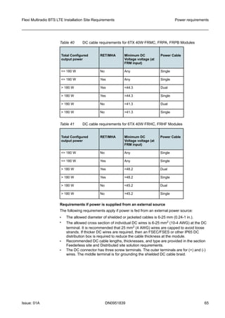
![The total power consumption of Flexi Cabinet Site Support Module depends on which
third-party configuration has been installed in the line terminal equipment space.
7.4.2 Power consumption of TDD Flexi RF Modules and RRHs
configurations
Table 44 Typical power consumptions for Flexi Multiradio BTS configurations in LTE
TDD
Configuration # of
cells
RF Power per
sector [W]
Estimated typical
power consumption
[W] at 48 VDC input
in 23°C, 68% TX
duty
1+1+1 MIMO 2TX 2300MHz
FSMF+FBBA + 6TX RF Module
3 10+10 518
1+1+1+1+1+1 MIMO 2TX 2300MHz
FSMF+2xFBBA + 2x6TX RF Module
6 10+10 911
1+1+1 MIMO 4TX 2300MHz
FSMF+FBBA + 2x6TX RF Module
3 10+10+10+10 826
2+2+2 MIMO 4TX 2300MHz
FSMF+FBBA + 2x6TX RF Module
6 2x5+2x5+2x5+2x5 826
1+1+1 MIMO 2TX 2600MHz
FSMF+FBBA + 8TX RF Module
3 10+10 586
2+2+2 MIMO 2TX 2600MHz
FSMF+FBBA + 8TX RF Module
6 2x5+2x5 586
2+2+2 MIMO 2TX 2600MHz
FSMF+FBBA + 2x8TX RF Module
6 2x5+2x5+2x5+2x5 1047
2+2+2 MIMO 2TX 2300MHz
FSMF+2xFBBA + 3x8TX RF Module
6 2x5+2x5+2x5+2x5 1423
1+1+1 MIMO 8TX 2600MHz
FSMF+2xFBBA + 3x8TX RF Module
3 10+10+10+10+10+
10+10+10
1423
2+2+2 MIMO 8TX 2600MHz
3x(FSMF+FBBA + 3x8TX RF Module)
6 2x5+2x5+2x5+2x5+
2x5+2x5+2x5+2x5
1758
1+1+1 MIMO 4TX 2300MHz
FSMF+FBBA + 3x4TX RRH Module
3 30+30+30+30 1689
1+1+1+1+1+1 MIMO 4TX 2300MHz
FSMF+2xFBBA + 6x4TX RRH Module
6 30+30+30+30 3253
2+2+2 MIMO 4TX 2300MHz
FSMF+FBBA + 3x4TX RRH Module
6 2x15+2x15+2x15+2
x15
1689
Power requirements Flexi Multiradio BTS LTE Installation Site Requirements
68 DN0951839 Issue: 01A](https://image.slidesharecdn.com/fleximultiradiobtslteinstallationsiterequirements-160323091037/85/Flexi-multiradio-bts-lte-installation-site-requirements-68-320.jpg)
![Table 44 Typical power consumptions for Flexi Multiradio BTS configurations in LTE
TDD (Cont.)
Configuration # of
cells
RF Power per
sector [W]
Estimated typical
power consumption
[W] at 48 VDC input
in 23°C, 68% TX
duty
2+2+2+2 MIMO 4TX 2300MHz
2x(FSMF+FBBA) + 4x4TX RRH Module
8 2x15+2x15+2x15+2
x15
2392
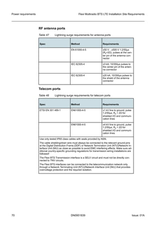
7.5 Lightning surge requirements
AC power port
Table 45 Switching and lightning transient requirements for AC power port
Spec Method Requirement
ETSI EN 301 489-1 EN 61000-4-5 ±2 kV line to ground (com-
mon), pulse 1.2/50µs,
Rs=(2Ω+ 10Ω)
±1.0 kV line to line (differ-
ential), pulse 1.2/50µs
(Rs=2Ω)
GR-1089 GR-1089 ±2 kV each phase conduc-
tor to green-wire ground,
pulse 1.2/50µs (Rs=2Ω)
±2 kV each phase conduc-
tor to neutral conductor,
pulse 1.2/50µs (Rs=2Ω)
±2 kV between neutral con-
ductor and green-wire
ground, pulse 1.2/50µs
(Rs=2Ω)
DC power port
Table 46 Surge immunity requirements for DC power port
Spec Method Requirement
- EN 61000-4-5 ±1 kV line to ground, pulse
1.2/50µs (Rs=2Ω)
±0,5 kV line to line, pulse
1.2/50µs (Rs=2Ω)
Flexi Multiradio BTS LTE Installation Site Requirements Power requirements
Issue: 01A DN0951839 69](https://image.slidesharecdn.com/fleximultiradiobtslteinstallationsiterequirements-160323091037/85/Flexi-multiradio-bts-lte-installation-site-requirements-69-320.jpg)

![10 Third-party cabinet requirements
Basic requirements for a third-party cabinet
The basic requirements for a third-party cabinet are the following:
• 19-inch cabinet with supporting side trays or plates (must meet the IEC 60297
Dimensions of mechanical structures of the 482.6 mm (19 in.) series standard)
f In cabinet installations, Flexi Multiradio module casings are needed to
ensure proper cooling and support for the module cores. When installing
modules in a third-party cabinet, do not remove the module cores from their
casings.
• Minimum depth 600 mm (23.6 in.)
• Rear air intake (Make sure that input air is evenly distributed between the installed
modules.)
• Front exhaust
• Proper cable routing
• The recommended constant ambient temperature for modules installed inside the
cabinet must be -35ºC - +45ºC (-31ºF - +113ºF)
• If the installation is a stand-alone rack (and no cabinet), NSN requires that the front
and the rear covers are used for safety purposes. A casing is required to mount the
rear cover.
For more information on the third-party cabinet installations, see
Installing modules inside a third-party cabinet in the Installing Flexi Multiradio Base
Station and Flexi Multiradio 10 Base Station Modules in Cabinets document.
Requirements for Flexi Multiradio BTS and Flexi Multiradio 10 Base
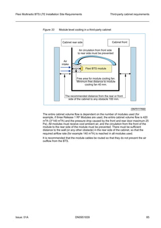
Station module level cooling in a third-party cabinet
Flexi BTS module is installed in the cabinet without the rear-side and front-side plastic
covers. The air volume flow requirement and pressure drop caused by the cabinet back
wall and front wall (door) for a single Flexi BTS module vary with module version, see
Table 63: Air volume flow and cabinet pressure drop. The module cooling fans’ minimum
distance to any obstacle in the rear side of the cabinet is 40 mm (1.6 in.). When planning
site cooling, BTS power consumption must be taken into consideration.
Table 63 Air volume flow and cabinet pressure drop
Variant Air Volume Flow Cabinet Pressure Drop [5]
FSMx, RF Module Release 1,
RF Module Release 2[1], RF
Module Release 3[2]
140 m3/h 25 Pa
ESMB/C, RF Module Release
2[3]
200 m3/h 51 Pa
RF Module Release 3[4] 210 m3/h 56 Pa
[1] All RF Module Release 2 variants except FXCA, FXDA, FXDJ, FXEA, FXFA/B
[2] All RF Module Release 2 variants except FXCB, FXDB, FXEB, FXFC
[3] FXCA, FXDA, FXDJ, FXEA, FXFA/B
[4] FXCB, FXDB, FXEB, FXFC, FRGT
[5] Includes combined pressure for both back wall and front wall (door)
Third-party cabinet requirements Flexi Multiradio BTS LTE Installation Site Requirements
84 DN0951839 Issue: 01A](https://image.slidesharecdn.com/fleximultiradiobtslteinstallationsiterequirements-160323091037/85/Flexi-multiradio-bts-lte-installation-site-requirements-84-320.jpg)


This document provides installation site requirements for Nokia Flexi Multiradio BTS LTE equipment, including environmental specifications, site requirements, power requirements, dimensions and weights of equipment, and compliance with EMC, RF and safety standards. It specifies the climatic conditions, clearances, grounding, power supply and other considerations for properly installing and operating the BTS equipment.


![Getting Started with Apache Spark: Big Data Made Simple [Free Meetup]](https://cdn.slidesharecdn.com/ss_thumbnails/apachesparkgettingstarted-260203175547-8361bcc3-thumbnail.jpg?width=640&height=640&fit=bounds)


