Downloaded 240 times
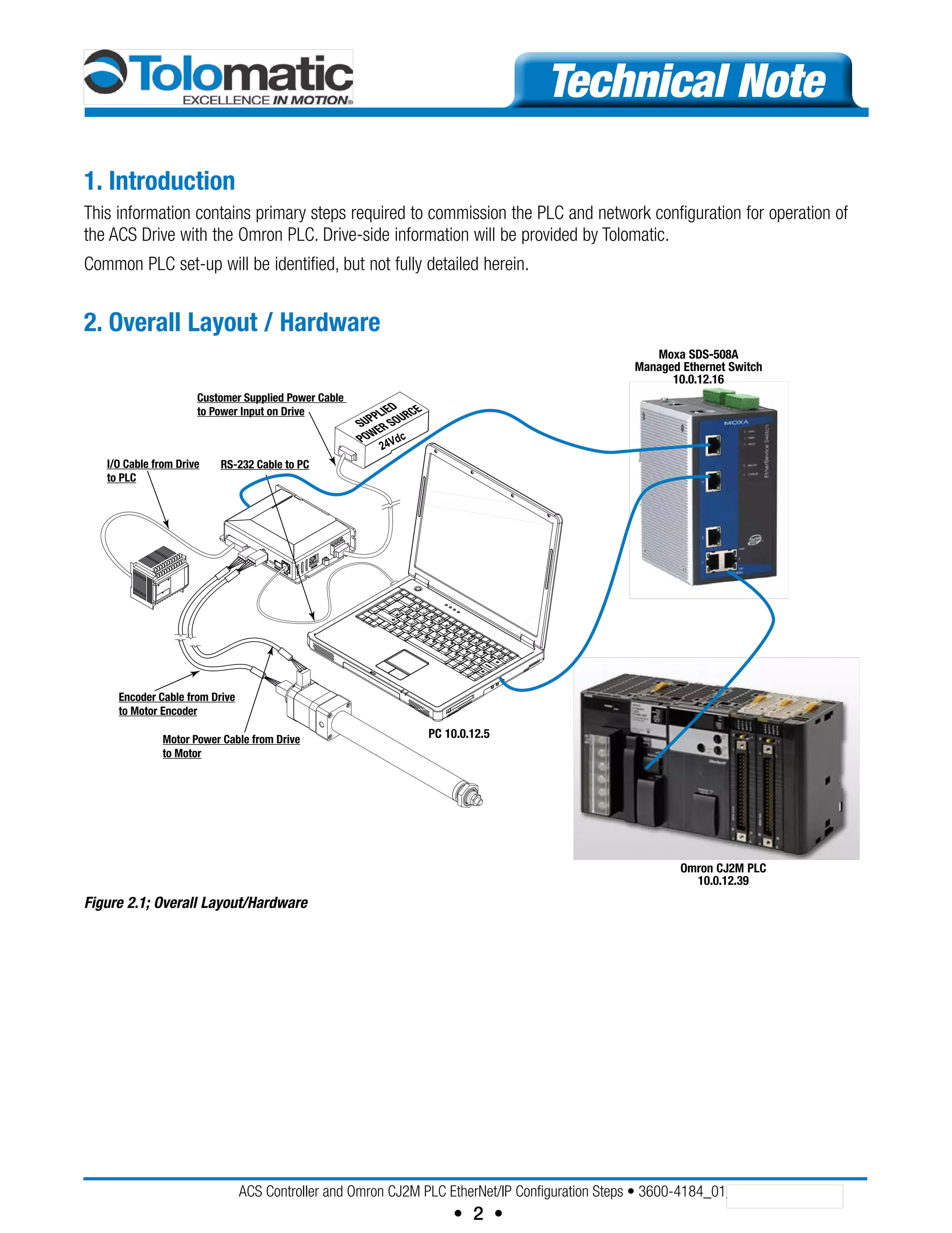
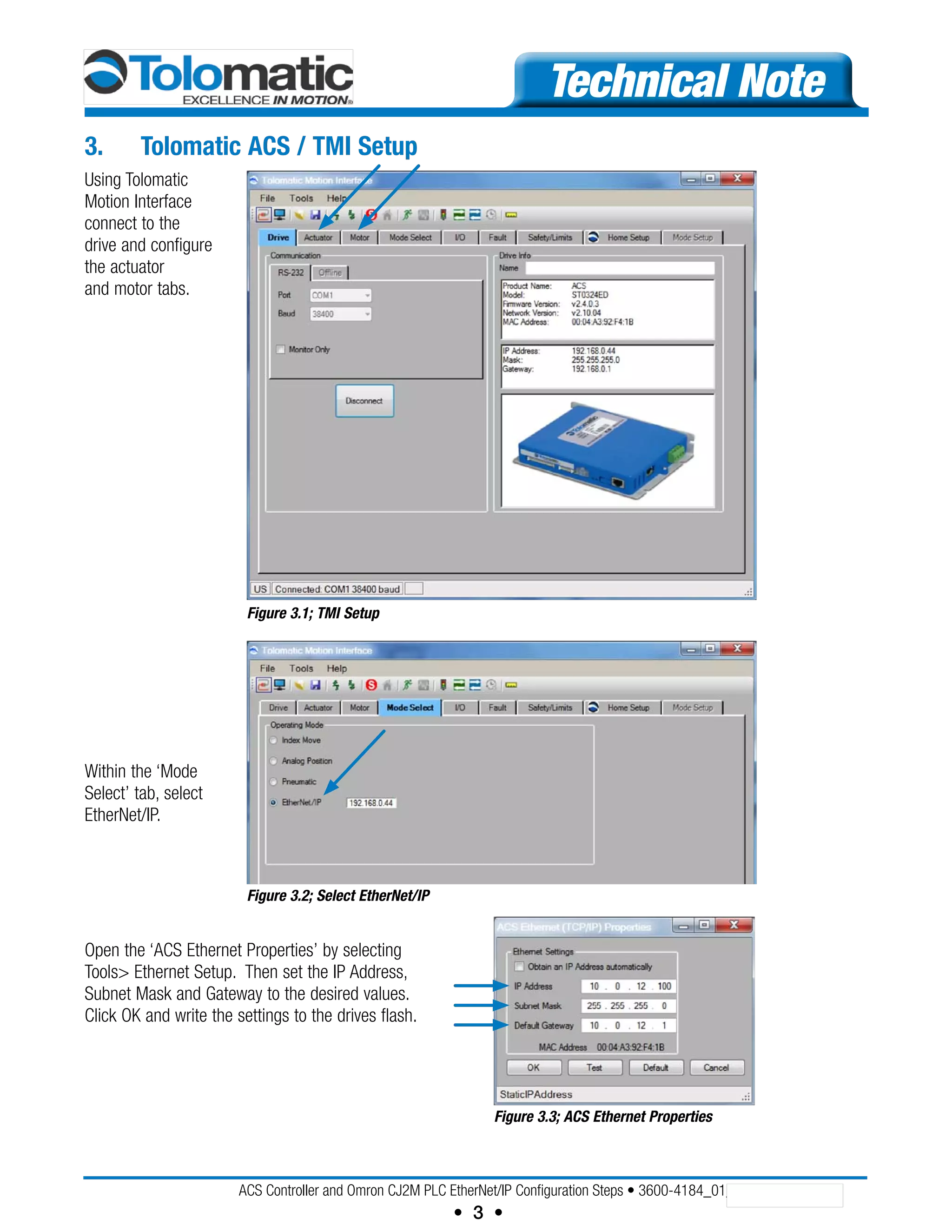


The document outlines the configuration steps for integrating an ACS drive with an Omron CJ2M PLC over Ethernet/IP. It includes sections on hardware setup, PLC commissioning, network configurator usage, and data exchange between the PLC and the ACS. These detailed instructions cover IP address settings, I/O table configuration, and tag setup for smooth operation and data communication.


![NB Designer Manual Operation [unlockplc.com]](https://cdn.slidesharecdn.com/ss_thumbnails/nbdesignermanualoperationunlockplc-150515045539-lva1-app6891-thumbnail.jpg?width=640&height=640&fit=bounds)


