Downloaded 154 times
![ROTATION
--------
ROTATION
----
,---- STATIONARY
KNIVES
ROTOR KNIFE (TYP)
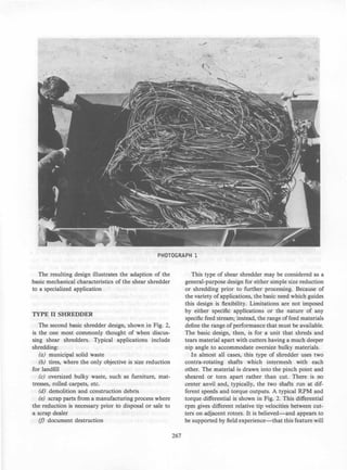
FIG. 1 TYPE I WIRE SHREDDER
[Input Torque Specifications: 38,200 ft-Ib/Shaft @ 19 rpm (51,800 N Shaft)]
insulated wire and cable to prepare it for feeding into
a mechanical reclamation system. In this instance, the
raw material is relatively homogeneous (when com
pared to solid waste) in composition but varies in form.
It may be, in a typical scrap processing operation, in
the form of dense bales weighing up to 2000 lb (900
kg) (as shown in Photograph 1), coils, bundles, or loose
wire. This mass of material then needs to be converted
into relatively loose, free-flowing pieces 6-24 in. (15-
60 cm) long, that can be fed into the first processing
operation, a close-tolerance radial knife granulator.
Three factors had to be taken into consideration in
the design of this type of shear shredder:
(a) The limitations of alternate processing methods:
small, manually-fed shears were quite labor-intensive
(as well as unsafe) while hydraulic guillotine shears
tended to compress the wire into dense blocks. Neither
of these methods could economically precut dense bales
(a process factor).
(b) The sensitivity of the downstream granulators
to surge or shock loads: either of the above methods
could result in overfeeding the downstream system and
the compressed material from hydraulic shears caused
more rapid wear in the granulator (again, a process
factor).
(c) The nature of the feed: the dense bales needed
to be tom apart yet the individual wires needed to be
cut, not stretched and tom.
266
The resultant design, shown in Fig. 1, incorporates
two counter-rotating shafts that do not intermesh with
each other. Instead, they cut against a stationary anvil
bar equipped with replaceable and adjustable knives.
At the same time, the knives have sufficient projection
to pull apart the dense mass of wire and cable. As the
knives on the two rotors pass between the stationary
knives they pull through, and cut into short lengths,
the tangled mass of raw material.
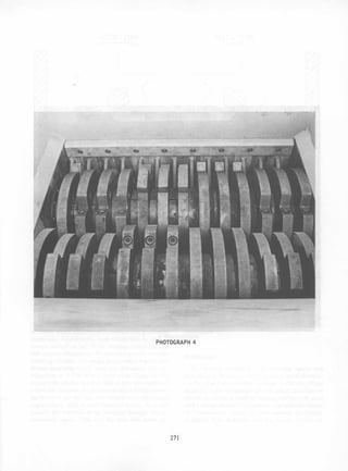
In Photograph 2 the rotor configuration is shown;
in the center can be seen a portion of the stationary
anvil which supports the stationary knives. The two
shafts are independently driven and can independently
reverse should an obstruction, or thick mass of ma
terial, be present. The result is a uniform flow of wire
and cable cut into short lengths (see Photograph 3)
which can be fed to the downstream processing system.
The unique feature of this type of shear shredder
makes it ideal for this one purpose. That same feature,
rotor knives cutting against stationary knives on a
center anvil, make it impractical for such materials as
municipal solid waste, tires, "white goods", and other
bulky waste. For those, the center anvil will result in
a drastic reduction in capacity due to bridging of ma
terial on the anvil. Additionally, the nip angle, or line
of attack of the cutters onto the material being shred
ded, is not sufficient to pull bulky items into the in
terface of the cutters.](https://image.slidesharecdn.com/1986-national-waste-processing-conference-28-160724152538/85/shredder-design-2-320.jpg)
![ROTATION
-----
ROTATION
----
HARDFACED
CUTTING
SURFACE
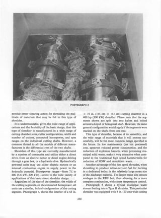
FIG. 2 TYPE II MSW SHREDDER
[Input Torque Specifications: 1 @ 32,000 ft-Ib/Shaft @ 32 rpm (43,400 N. m Shaft @ 32 rpm);
1 @ 57,000 ft-Ib/Shaft @ 16 rpm (77,306 N. m Shaft @ 16 rpm)]
SCREEN PERCENT RETAINED
SIZE. IN.
AVG. MIN. MAX.
+4 19.3 9.7 32.9
+2 30.7 23.0 35.0
+1 19.2 14.9 23.9
+1/2 13.2 8.9 17.4
+1/4 9.3 6.2 12.0
PAN 8.3 5.1 10.3
FIG. 3 02-03 DECEMBER 1980 SIZE DISTRIBUTION OF
SHREDDER OUTPUT: ELEVEN SAMPLINGS FROM 11.2
TO 28.4 Ib; AVERAGE SIZE 18.8 Ib; AVERAGE BULK
DENSITY 5.4 pcf
270
quirements and the specific nature of the feed material.
Specifically:
(a) The shredder output must be reasonably uni
form in shape, of a size that can be readily burned,
and free of long strips of rubber.
(b) The raw material is bulky, flexible, elastic, and
not easy to engage in the interface between the cutters.
As a result, this Type III shredder design incorpo
rates features from the first two types, and, like Type
I, adds some very unique features to meet the require
ments of its specific feed material. Figure 4 illustrates
a typical cross-section through the cutting chamber of
this design.
First, because of the elasticity of the feed material,
and to give better control over the particle size pro
duced, it borrows the idea of replaceable cutting edges
from the Type I shredder. Next, froIJ1 a Type II shred
der, it borrows the idea of the intermeshing rotors and
eliminates the center anvil, to ease the entrance of the
bulky feed material into the cutting interface and re
duce the possibility of material bridging.](https://image.slidesharecdn.com/1986-national-waste-processing-conference-28-160724152538/85/shredder-design-6-320.jpg)
![ROTATION ROTATION
�-------- -------..-
- - - -
ROTATION ROTATION
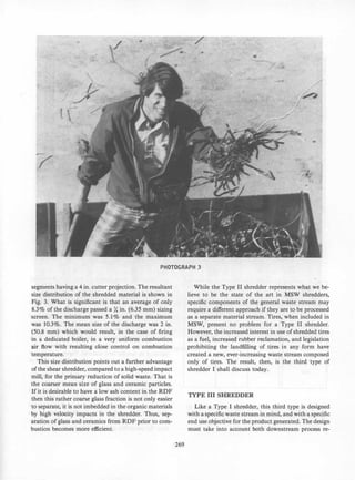
FIG. 4 TYPE III TIRE SHREDDER
[Input Torque Specifications: 26,500 ft-Ib/Shaft @ 19 rpm (35,900 N Shaft)]
These two features, by themselves, however, will not
eliminate the possibility of producing the long strips
of rubber which interfere with downstream processing
operations. Additionally, tires would still be free to
bounce around on top of the rotating cutters, greatly
reducing net throughput. To solve this specific material
handling problem, the design incorporates a set of star
shaped feed rolls which push the individual tire car
casses one at a time into cutting zone. These feeders
engage the tire carcass and feed it into the cutters at
a feed rate less than the peripheral speed of the cutters.
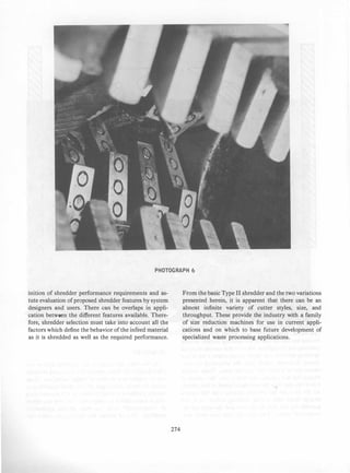
As the tires are fed into the cutting zone the cutters
engage them with a true shearing action. It is not
possible for the tires to be extruded through the in
termeshed cutters. This cuts the tires into more uni-
273
form pieces and eliminates the production of long strips
of rubber. A typical Type III Shredder is shown in
Photograph 6.
SUMMARY
As has been illustrated in the previous figures and
photographs, the basic concept of a low-speed shredder
can be subject to a number of design variations. These
adapt the basic advantages of low-speed shredding to
specific problems in waste processing and provide users
with a wider choice in equipment-or even the option
of "customized" units-to meet specific application
problems. This, of course, will also require closer def-](https://image.slidesharecdn.com/1986-national-waste-processing-conference-28-160724152538/85/shredder-design-9-320.jpg)

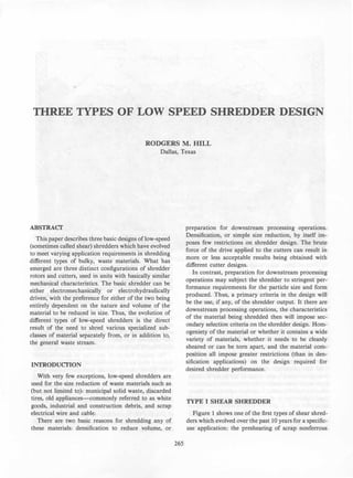
This document describes three types of low-speed shredders. Type I shredders have stationary knives and two counter-rotating shafts for shredding scrap wire and cable. Type II shredders, the most common design, have two intermeshing counter-rotating shafts for shredding a variety of materials. Type III shredders are designed for shredding tires, with intermeshing shafts, replaceable cutting edges, and star-shaped feed rolls to push tires into the cutting zone. The different designs illustrate how low-speed shredders can be adapted to specific waste streams and processing needs.