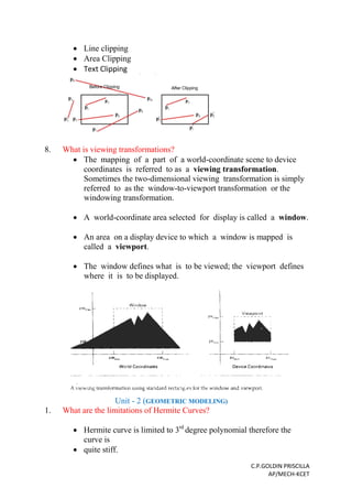
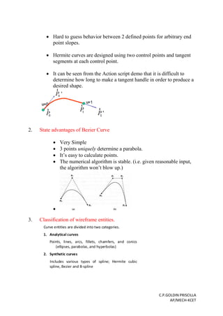
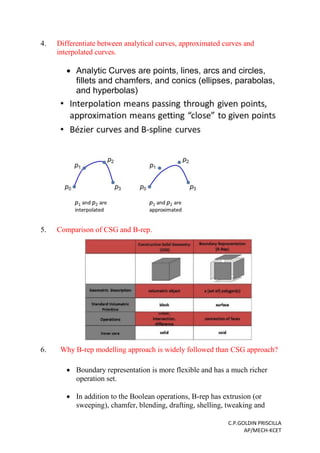
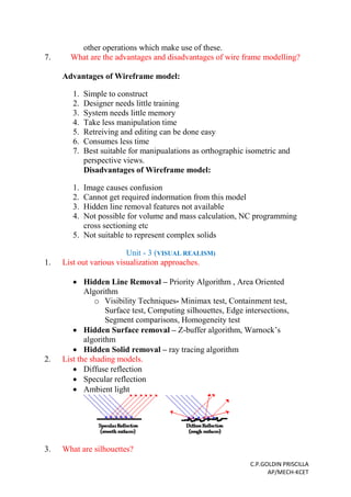
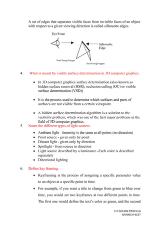
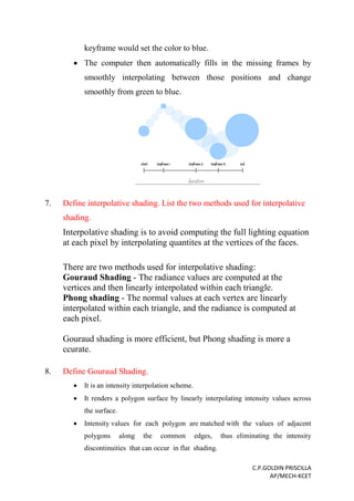
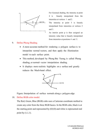
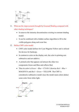
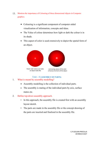
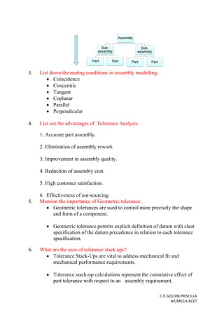
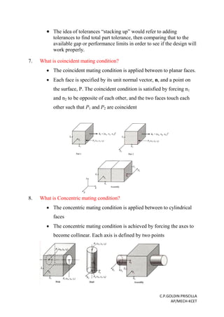
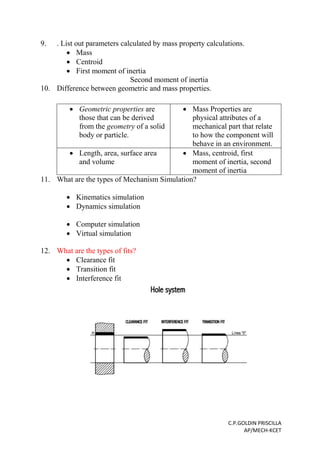
The document provides a summary of important two mark questions and answers related to the topics of computer aided design (CAD). It includes questions about the design process, applications of CAD in mechanical engineering, geometric transformations, homogeneous coordinates, product design synthesis, the product lifecycle, clipping, viewing transformations, limitations of Hermite curves, advantages of Bezier curves, wireframe modeling approaches, visualization techniques, lighting models, keyframing, interpolative shading methods like Gouraud and Phong shading, color models like RGB and CMY. The document is organized by topic into different units covering fundamentals of computer graphics, geometric modeling, and visual realism.
The document discusses geometric modeling which is the foundation of computer-aided design (CAD). It describes the different types of geometric models including graphical models, curve models, surface models, and solid models. Graphical models include wireframe models and can be graphically deficient. Curve models must satisfy boundary conditions at start and end points. When curves are joined, they can have C0, C1 or C2 continuity depending on matching of points, tangents or curvature. The document provides examples of each type of continuity for composite curves.
CAD software can be divided based on the modeling technique used, including 2D, basic 3D, sculpted surfaces, and 3D solid modeling. Geometric modeling is a fundamental part of CAD tools and refers to techniques for developing efficient representations of a design's geometric aspects. The main geometric modeling approaches are wireframe modeling, surface modeling, and solid modeling. Solid modeling provides the most complete description of an object's shape, surface, volume, and density.
This document discusses different types of geometric modeling methods including wireframe, surface, and solid modeling. Wireframe modeling uses points and lines to define objects but does not represent actual surfaces or volumes. Surface modeling defines the outer surfaces of an object. Solid modeling precisely defines the enclosed volume of an object using its faces, edges, and vertices. Constructive solid geometry and boundary representation are two common solid modeling techniques. CSG uses Boolean operations to combine primitive shapes, while boundary representation stores topological information about faces, edges, and vertices. Feature-based modeling allows shapes to be created through operations like extruding, revolving, sweeping, and filling.
This document provides an overview of geometric modeling techniques used in computer aided design (CAD). It discusses representation of curves including Hermite curves, Bezier curves, B-spline curves, and rational curves. It also covers surface modeling techniques such as surface patches, Coons patches, and Bicubic patches. For solid modeling, it describes constructive solid geometry (CSG) and boundary representation (B-rep) techniques. CSG uses boolean operations on primitives to create models while B-rep defines models based on their bounding faces, edges and vertices.
This document discusses geometric modeling and curves. It provides information on:
- Geometric modeling is the process of creating mathematical models of physical objects and systems using computer software.
- There are different types of geometric models including wireframe, surface, and solid modeling.
- Curves can be represented mathematically in both implicit and parametric forms, with parametric being most common in modeling as it overcomes limitations of other forms.
- Parametric curves define a curve using a parameter, where varying the parameter provides points on the curve. Common parametric representations include lines, conics, and higher-order curves composed of simpler curve segments.
1) Geometric modeling is a fundamental CAD technique that represents objects using points, lines, curves, surfaces or solids.
2) Early techniques included wireframe and surface modeling but they were ambiguous and lacked topological data.
3) Solid modeling techniques like CSG and B-Rep overcome these issues by representing objects unambiguously using their volume and topology.
4) Feature-based modeling further advanced CAD by modeling objects parametrically using high-level features like holes and rounds.
The document discusses geometric modeling which plays a crucial role in CAD/CAM/CAE systems. It describes three main types of geometric modeling: wireframe, surface, and solid modeling. Wireframe modeling uses lines and curves to represent an object, surface modeling uses surfaces like planes, and solid modeling creates a complete 3D representation of an object. Parametric curves and issues of continuity between curves are also covered. Cubic spline curves are discussed as an example of synthetic curves used in surface modeling.
This document discusses solid modeling techniques in CAD/CAM systems. It describes solid modeling as representing objects as enclosed volumes defined by vertices, edges, surfaces, weight and volume. Two main solid modeling techniques are covered - Constructive Solid Geometry (CSG) and Boundary Representation (B-Rep). CSG uses Boolean operations to combine primitive shapes while B-Rep defines models by their bounding faces, edges and vertices. The document also discusses parametric modeling and how it allows dimensions to control the model geometry.
Solid modeling-Sweep Representation and B-representationDestro Destro
Solid modeling is a computer representation of a physical 3D object that allows for its creation and visualization in digital form. A solid model contains both geometric information about the object's shape, size, and angles as well as topological information about how its parts are connected. Solid models provide a more complete representation than earlier wireframe models and can be represented using techniques like boundary representation, sweeps along trajectories, or as polyhedrons with flat faces, edges and vertices.
This document provides an overview of geometric modeling techniques used in computer aided design (CAD). It discusses representation of curves including Hermite curves, Bezier curves, B-spline curves, and rational curves. It also covers surface modeling techniques such as surface patches, Coons patches, bicubic patches, Bezier surfaces, and B-spline surfaces. For solid modeling, it describes constructive solid geometry (CSG) and boundary representation (B-rep) techniques. CSG uses boolean operations on primitives to create models while B-rep models objects based on their bounding faces, edges, and vertices.
All physical objects have 3D boundaries that define their shape. Surface modeling uses points, lines, and faces to define these boundaries mathematically. There are several types of surfaces, including plane, ruled, revolved, and freeform surfaces. Revolved surfaces are created by rotating a profile around an axis, generating surfaces like cylinders and cones. Curves and surfaces are essential for modeling complex shapes encountered in engineering designs.
This document discusses different methods of 3D modeling, including wireframe modeling, surface modeling, and solid modeling. It provides details on each modeling method, including their advantages and disadvantages. For example, wireframe modeling only contains edge information and cannot represent actual solids, while solid modeling defines enclosed volumes and allows simulation under real-life conditions. The document also covers specific solid modeling techniques like boundary representation and constructive solid geometry, as well as parametric modeling concepts.
The document provides instructions for creating a finite element analysis model of a tension fitting in MSC Patran. The steps include:
1. Creating the parasolid solid model of the tension fitting using boolean operations and other parasolid tools.
2. Generating a tetrahedral mesh and assigning material properties and loads representing tension.
3. Running the finite element analysis in MSC Nastran and post-processing the results in Patran to view stress and deformation.
The document outlines 17 detailed steps to guide the user through the entire modeling and analysis process in Patran and Nastran.
This document discusses different methods for representing curves in geometric modeling, including non-parametric and parametric representations. Non-parametric representations can be explicit, using equations relating x, y, and z, or implicit, with no distinction between dependent and independent variables. Parametric representations describe variables in terms of a parameter, allowing for multi-valued and flexible curves. Specific curve types discussed include Bezier curves, defined by control points, and B-spline curves, which separate the polynomial order from the number of control points.
The document discusses different methods for modeling solid objects in 3D, including constructive solid geometry (CSG) and boundary representation (B-Rep). CSG uses boolean operations on primitive solids, represented as a tree structure, while B-Rep defines solids by their enclosing faces, edges and vertices with topological connectivity. Both have advantages such as unambiguous definitions but also challenges around complexity, storage or modeling restrictions. Hybrid approaches combine benefits of both methods.
2D drawings are not ideal for representing 3D objects as they lack a Z axis. There are three main types of 3D models: wireframe, surface, and solid models. Wireframe models only contain edges and vertices and cannot represent complex surfaces. Surface models include edges, vertices and exterior surfaces but provide no interior details. Solid models are the current standard as they contain edges, vertices, exterior surfaces and interior details, providing an unambiguous representation of an object that can be used for engineering analysis.
The document discusses different types of geometric models used in modeling including wireframe models, surface models, and solid models. It provides details on each type of model, including their advantages and disadvantages. Wireframe models are the simplest but use the least amount of memory and are easy to create. Surface models are more complex but provide more geometric constraints for engineering applications. Solid models provide the most complete representation and allow calculation of mass properties. The document also discusses different modeling approaches like constructive solid geometry (CSG) and boundary representation (B-rep) used for solid modeling.
Wireframe models represent 3D objects using geometric primitives like points, lines, and polygons. They connect vertices with edges to form polygonal nets or meshes. There are three common representations: explicit vertex lists that store each vertex coordinate; polygon listings that define polygons through vertex indices; and explicit edge listings that store each unique edge and define polygons through edge indices. Wireframe models are easy to create but cannot represent curved surfaces or differentiate interior/exterior.
This document discusses different types of surface entities used in CAD/CAM systems. It describes analytic surface entities like planes, ruled surfaces, surfaces of revolution, and tabulated cylinders. It also covers synthetic surface entities, including bicubic Hermite spline surfaces, B-spline surfaces, rectangular and triangular Bezier patches, rectangular and triangular Coons patches, and Gordon surfaces. Plane surfaces are defined by three points, ruled surfaces interpolate between two boundary curves, and surfaces of revolution rotate a curve around an axis. Bezier and B-spline surfaces can approximate input data without passing through all points.
This document discusses techniques for modeling curves and surfaces in computer graphics. It introduces three common representations of curves and surfaces: explicit, implicit, and parametric forms. It focuses on parametric polynomial forms, specifically discussing cubic polynomial curves, Hermite curves, Bezier curves, B-splines, and NURBS. It also covers rendering curves and surfaces by evaluating polynomials, recursive subdivision of Bezier polynomials, and ray casting for implicit surfaces like quadrics. Finally, it discusses mesh subdivision techniques like Catmull-Clark and Loop subdivision for generating smooth surfaces.
The document discusses wireframe modeling in computer-aided design. It defines wireframe modeling as consisting only of points and curves without faces. A wireframe model uses a vertex table and edge table to define geometry. Advantages include ease of creation and low hardware/software requirements, while disadvantages include difficulty visualizing designs. The document also covers classifications of curves used in wireframe modeling like analytical, synthetic, and parametric curves. It provides examples of representing common curves like lines, circles, and splines parametrically.
Geometric modeling is an important part of CAD systems. There are several techniques for geometric modeling including wireframe modeling, surface modeling, and solid modeling. Solid modeling uses half-spaces and boolean operations to define objects by their volume and boundaries. Constructive solid geometry (CSG) and boundary representation (B-rep) are two common solid modeling techniques. CSG uses predefined geometric primitives and boolean operations to combine them. B-rep represents solids as collections of boundary surfaces and records the geometry and topology of the surfaces.
This document discusses different types of surface models used in computer graphics, including:
- Plane, ruled, surface of revolution, tabulated, bilinear, Coons patch, and bicubic surfaces. Plane and ruled surfaces are linear, while surfaces of revolution and tabulated surfaces are axisymmetric. Bilinear surfaces are generated by interpolating 4 endpoints and are useful for finite element analysis. Coons patches interpolate 4 edge curves. Bicubic surfaces use parametric curves and interpolation of control points to define smooth surfaces.
This document summarizes different types of surfaces that are important from a CAD/CAM perspective. It discusses analytic surfaces like planes, ruled surfaces, tabulated surfaces, and surfaces of revolution which are defined by equations. It also discusses synthetic surfaces like Hermite bi-cubic surfaces, Bezier surfaces, B-spline surfaces, Coons surfaces, fillet surfaces, and offset surfaces which are defined by a set of data points and approximated with polynomials. The document provides examples and definitions of each surface type.
Cad ala brep, csg and sweep representation gtuShrey Patel
This document provides an overview of three common solid modeling techniques: boundary representation (B-rep), constructive solid geometry (CSG), and sweep representation. B-rep models represent solid objects by their boundaries and surfaces. CSG models combine basic geometric primitives using set operations like union and intersection. Sweep representation builds models by sweeping a profile along a path, allowing extruded and revolved solids. The document discusses the topological and geometric components of B-rep models and provides examples of primitives, operations, and types of CSG and sweep models.
This document provides a summary of important two-mark questions and answers related to the topics covered in a Computer Aided Design (CAD) course. It includes questions from five units:
1. Fundamentals of computer graphics including the design process, applications of CAD, geometric transformations, and homogeneous coordinates.
2. Geometric modeling covering curves, wireframe modeling, boundary representation vs constructive solid geometry.
3. Visual realism such as visualization techniques, lighting models, shading methods and color models.
4. Assembly of parts including assembly modeling, mating conditions, tolerancing, mass properties and interference checking.
5. CAD standards including the need for data exchange standards and important standards for exchange
Building 3D Morphable Models from 2D ImagesShanglin Yang
The document discusses building 3D morphable models from 2D images. It proposes using subdivision surfaces which require fewer parameters than meshes to represent 3D objects. An energy function is formulated that matches image silhouettes and constraints, enforces normal consistency, and includes smoothness terms. Optimization first uses global search to estimate the contour generator and then local optimization to estimate pose parameters and refine the model. Experiments demonstrate reconstructing dolphin shapes from images.
Three-dimensional viewing involves considering the spatial position from which an object can be viewed, projecting 3D descriptions of objects onto a 2D viewing surface, and enclosing visible space within clipping boundaries. The viewing pipeline involves a series of transformations that convert 3D coordinates to 2D device coordinates for display. Parallel and perspective projections are two basic projection methods that transform 3D positions to 2D viewing coordinates in different ways.
The document provides legal notices and disclaimers for an Intel presentation. It states that the presentation is for informational purposes only and that Intel makes no warranties. It also notes that Intel technologies' features and benefits depend on system configuration and may require enabled hardware, software or service activation. Performance varies depending on system configuration. The document further states that sample source code is released under the Intel Sample Source Code License Agreement and that Intel and its logo are trademarks.
3D Reconstruction from Multiple uncalibrated 2D Images of an ObjectAnkur Tyagi
3D reconstruction is the process of capturing the shape and appearance of real objects. In this project we are using passive methods which only use sensors to measure the radiance reflected or emitted by the objects surface to infer its 3D structure.
This document discusses different types of geometric modeling methods including wireframe, surface, and solid modeling. Wireframe modeling uses points and lines to define objects but does not represent actual surfaces or volumes. Surface modeling defines the outer surfaces of an object. Solid modeling precisely defines the enclosed volume of an object using its faces, edges, and vertices. Constructive solid geometry and boundary representation are two common solid modeling techniques. CSG uses Boolean operations to combine primitive shapes, while boundary representation precisely defines the boundaries and topology of a model.
Intelligent Auto Horn System Using Artificial IntelligenceIRJET Journal
The document proposes an intelligent auto horn system using artificial intelligence to reduce unnecessary noise pollution from vehicle horns. The system uses sensors and cameras to collect environmental data and an on-board computer uses AI techniques like SIFT, SURF and other computer vision algorithms to process the data. Based on factors like the distance between objects, road width, and object size, the AI will control the horn sound horizontally and vertically. The system aims to only sound the horn as loud as needed based on the situation to reduce noise pollution while maintaining safety. The system is described as not compromising safety and automatically adjusting the horn sound using fixed horn mechanisms based on AI analysis of the environment.
This document presents a facial expression recognition system that uses Bezier curves to approximate facial features. Facial features are extracted using knowledge of face geometry and approximated by 3rd order Bezier curves representing the relationship between feature movements and expression changes. Experimental results show the method can recognize faces with over 90% accuracy. The proposed system first detects the face, then extracts features like eyes, mouth, and eyebrows. Contours are extracted from these regions and used to generate feature vectors, which are then processed with a neural network to determine the expression. The methodology involves preprocessing the image, skin color conversion, connected component analysis, binary conversion, and extracting eye and mouth features to detect expressions by comparing Bezier curves to a database of expressions.
This document discusses various techniques for achieving visual realism in 3D computer graphics, including hidden surface removal algorithms, shading methods, and color models. It describes algorithms for hidden line elimination, hidden surface removal, and hidden solid removal. It also covers shading techniques like constant intensity shading, Gouraud shading, and Phong shading. Finally, it discusses color models such as RGB, CMY, HSV, and HSL that can be used for computer graphics applications.
IJERA (International journal of Engineering Research and Applications) is International online, ... peer reviewed journal. For more detail or submit your article, please visit www.ijera.com
Curves play a significant role in CAD modeling, especially for generating wireframe models. There are three main types of computer-aided design models: wireframe, surface, and solid. Wireframe models use only points and curves to represent an object in the simplest form. Curves can be classified as analytical, interpolated, or approximated. Analytical curves have fixed mathematical equations, interpolated curves pass through given data points in a fixed form, and approximated curves provide the most flexibility in complex shape creation. Parametric equations are preferred over non-parametric equations for representing curves in CAD programs. Common analytical curves include lines, circles, ellipses, parabolas, and hyperbolas. Interpolated curves can
The document outlines the course objectives, outcomes, examination scheme, and units of a Computer Graphics course. The course aims to acquaint students with basic concepts, algorithms, and techniques of computer graphics through understanding, applying, and creating graphics using OpenGL. Students will learn about primitives, transformations, projections, lighting, shading, animation and gaming. The course assessment includes a mid-semester test, end-semester test, and covers topics ranging from graphics primitives to fractals and animation.
This document proposes using dual back-to-back Kinect sensors mounted on a robot to capture a 3D model of a large indoor scene. Traditionally, one Kinect is slid across an area, but this requires prominent features and careful handling. The dual Kinect setup requires calibrating the relative pose between the sensors. Since they do not share a view, traditional calibration is not possible. The authors place a dual-face checkerboard on top with a mirror to enable each Kinect to view the same calibration object. This allows estimating the pose between the sensors using a mirror-based algorithm. After capturing local models, the two Kinect views can be merged into a combined 3D model with a larger field of view.
This document discusses techniques for achieving visual realism in geometric modeling. It covers topics like hidden line removal, hidden surface determination, shading models, transparency, reflection, and camera models. The goal of visual realism is to generate images that capture effects of light interacting with physical objects similarly to how we see the real world. This involves modeling objects and lighting conditions, determining visible surfaces, assigning color to pixels, and creating animated sequences. Realistic images find applications in simulation, design, entertainment, research, and control.
The document discusses various techniques for representing and describing image regions after segmentation. It describes choosing external or internal representation based on focusing on shape or region properties. Common representation techniques include chain codes, polygonal approximations, signatures, boundary segments, and skeletons. Descriptors are then used to represent regions in a compact, invariant form for further processing and analysis.
This document summarizes a research paper that implemented a pipelined CORDIC architecture in Simulink to generate sine and cosine values. The CORDIC algorithm uses only shift and add operations to perform trigonometric and other elementary functions. It was applied here in rotation mode to simultaneously compute sine and cosine of an input angle. A 12-stage pipelined CORDIC architecture was modeled in Simulink. The shifts and constants were hardwired to reduce resources and latency. Testing with an input of 0.6 radians showed accurate outputs for sine and cosine. The implementation demonstrated the utility of Simulink for modeling hardware systems and algorithms like CORDIC.
Medial Axis Transformation based Skeletonzation of Image Patterns using Image...IOSR Journals
1) The document discusses extracting the medial axis transform (MAT) of an image pattern using the Euclidean distance transform. The image is first converted to binary, then the Euclidean distance transform is used to compute the distance of each non-zero pixel to the closest zero pixel.
2) The medial axis transform represents the core or skeleton of an image pattern. There are different algorithms for extracting the skeleton or medial axis, including sequential and parallel algorithms. The skeleton provides a simple representation that preserves topological and size characteristics of the original shape.
3) The document provides background on medial axis transforms and different skeletonization algorithms. It then describes preparing the binary image and applying the Euclidean distance transform to extract the MAT and skeleton
Electric vehicle and photovoltaic advanced roles in enhancing the financial p...IJECEIAES
Climate change's impact on the planet forced the United Nations and governments to promote green energies and electric transportation. The deployments of photovoltaic (PV) and electric vehicle (EV) systems gained stronger momentum due to their numerous advantages over fossil fuel types. The advantages go beyond sustainability to reach financial support and stability. The work in this paper introduces the hybrid system between PV and EV to support industrial and commercial plants. This paper covers the theoretical framework of the proposed hybrid system including the required equation to complete the cost analysis when PV and EV are present. In addition, the proposed design diagram which sets the priorities and requirements of the system is presented. The proposed approach allows setup to advance their power stability, especially during power outages. The presented information supports researchers and plant owners to complete the necessary analysis while promoting the deployment of clean energy. The result of a case study that represents a dairy milk farmer supports the theoretical works and highlights its advanced benefits to existing plants. The short return on investment of the proposed approach supports the paper's novelty approach for the sustainable electrical system. In addition, the proposed system allows for an isolated power setup without the need for a transmission line which enhances the safety of the electrical network
A SYSTEMATIC RISK ASSESSMENT APPROACH FOR SECURING THE SMART IRRIGATION SYSTEMSIJNSA Journal
The smart irrigation system represents an innovative approach to optimize water usage in agricultural and landscaping practices. The integration of cutting-edge technologies, including sensors, actuators, and data analysis, empowers this system to provide accurate monitoring and control of irrigation processes by leveraging real-time environmental conditions. The main objective of a smart irrigation system is to optimize water efficiency, minimize expenses, and foster the adoption of sustainable water management methods. This paper conducts a systematic risk assessment by exploring the key components/assets and their functionalities in the smart irrigation system. The crucial role of sensors in gathering data on soil moisture, weather patterns, and plant well-being is emphasized in this system. These sensors enable intelligent decision-making in irrigation scheduling and water distribution, leading to enhanced water efficiency and sustainable water management practices. Actuators enable automated control of irrigation devices, ensuring precise and targeted water delivery to plants. Additionally, the paper addresses the potential threat and vulnerabilities associated with smart irrigation systems. It discusses limitations of the system, such as power constraints and computational capabilities, and calculates the potential security risks. The paper suggests possible risk treatment methods for effective secure system operation. In conclusion, the paper emphasizes the significant benefits of implementing smart irrigation systems, including improved water conservation, increased crop yield, and reduced environmental impact. Additionally, based on the security analysis conducted, the paper recommends the implementation of countermeasures and security approaches to address vulnerabilities and ensure the integrity and reliability of the system. By incorporating these measures, smart irrigation technology can revolutionize water management practices in agriculture, promoting sustainability, resource efficiency, and safeguarding against potential security threats.
Advanced control scheme of doubly fed induction generator for wind turbine us...IJECEIAES
This paper describes a speed control device for generating electrical energy on an electricity network based on the doubly fed induction generator (DFIG) used for wind power conversion systems. At first, a double-fed induction generator model was constructed. A control law is formulated to govern the flow of energy between the stator of a DFIG and the energy network using three types of controllers: proportional integral (PI), sliding mode controller (SMC) and second order sliding mode controller (SOSMC). Their different results in terms of power reference tracking, reaction to unexpected speed fluctuations, sensitivity to perturbations, and resilience against machine parameter alterations are compared. MATLAB/Simulink was used to conduct the simulations for the preceding study. Multiple simulations have shown very satisfying results, and the investigations demonstrate the efficacy and power-enhancing capabilities of the suggested control system.
International Conference on NLP, Artificial Intelligence, Machine Learning an...gerogepatton
International Conference on NLP, Artificial Intelligence, Machine Learning and Applications (NLAIM 2024) offers a premier global platform for exchanging insights and findings in the theory, methodology, and applications of NLP, Artificial Intelligence, Machine Learning, and their applications. The conference seeks substantial contributions across all key domains of NLP, Artificial Intelligence, Machine Learning, and their practical applications, aiming to foster both theoretical advancements and real-world implementations. With a focus on facilitating collaboration between researchers and practitioners from academia and industry, the conference serves as a nexus for sharing the latest developments in the field.
KuberTENes Birthday Bash Guadalajara - K8sGPT first impressionsVictor Morales
K8sGPT is a tool that analyzes and diagnoses Kubernetes clusters. This presentation was used to share the requirements and dependencies to deploy K8sGPT in a local environment.
ACEP Magazine edition 4th launched on 05.06.2024Rahul
This document provides information about the third edition of the magazine "Sthapatya" published by the Association of Civil Engineers (Practicing) Aurangabad. It includes messages from current and past presidents of ACEP, memories and photos from past ACEP events, information on life time achievement awards given by ACEP, and a technical article on concrete maintenance, repairs and strengthening. The document highlights activities of ACEP and provides a technical educational article for members.
Literature Review Basics and Understanding Reference Management.pptxDr Ramhari Poudyal
Three-day training on academic research focuses on analytical tools at United Technical College, supported by the University Grant Commission, Nepal. 24-26 May 2024
6th International Conference on Machine Learning & Applications (CMLA 2024)ClaraZara1
6th International Conference on Machine Learning & Applications (CMLA 2024) will provide an excellent international forum for sharing knowledge and results in theory, methodology and applications of on Machine Learning & Applications.
6th International Conference on Machine Learning & Applications (CMLA 2024)
Two marks with answers ME6501 CAD
1. C.P.GOLDIN PRISCILLA
AP/MECH-KCET
ME6501- COMPUTER AIDED DESIGN (CAD)
IMPORTANT TWO MARK QUESTIONS WITH ANSWERS
UNIT 1 TO 5
Unit -1(FUNDAMENTALS OF COMPUTER GRAPHICS)
1. What is the design process? Mention the steps involved in Shigley’s
model for the design process.
Design process is an approach for breaking down a large project into
manageable portions.
Recognition of need
Definition of Problem
Synthesis
Analysis and Optimization
Evaluation
Presentation
2. Mention any four applications of computer aided design in Mechanical
Engineering.
Computer-aided engineering (CAE) and Finite element analysis (FEA)
Computer-aided manufacturing (CAM) including instructions to
Computer Numerical Control (CNC) machines
Photorealistic rendering and Motion Simulation.
Document management and revision control using Product Data
Management
3. List and differentiate the types of 2D geometric transformations.
Translation- moves an object to a different position on the screen.
Rotation - rotate the object at particular angle θ (theta) from its
origin.
Scaling - change the size of an object
Reflection - mirror image of original object
Shear - slants the shape of an object
2. C.P.GOLDIN PRISCILLA
AP/MECH-KCET
4. What is Homogeneous Coordinate
In homogeneous coordinates, we add a third coordinate to a point.
Instead of being represented by a pair of numbers (x,y), each point
is represented by a triple (x,y,W).
Two sets of homogeneous coordinates (x,y,W) and (x',y',W')
represent the same point if one is a multiple of the other. Thus,
(4,5,6) and (8,10,12) are the same points represented by different
coordinate triples.
"That is, each point has many different homogeneous coordinate
representations. Also one of the homogeneous coordinates must be
nonzero: (0,0,0) is not allowed. If the W coordinate is nonzero, we
can divide by it: (x,y,W) represents the same point as (x/W, y/W,
1).
When W is nonzero, we normally do this division, and the numbers
x/W and y/W are called the cartesian coordinates of the
homogeneous point. The points with W=0 are called points of
infinity.
5. What do you mean by synthesis of design?
Synthesis is a scheme to generate a possible way the product work.
It will also be called as concept design.
In the design process a number of concepts will be identified and
then the best concept is chosen for further development.
6. List the various stages in the life cycle of a product
Developing the product concept
Evolving the design
Engineering the Product
Manufacturing the product
Marketing and
servicing
7. Define Clipping.
Any procedure that identifies those portions of a picture that are
either inside or outside of a specified region or space is known as
clipping.
Types of Clipping
Point Clipping
3. C.P.GOLDIN PRISCILLA
AP/MECH-KCET
Line clipping
Area Clipping
Text Clipping
8. What is viewing transformations?
The mapping of a part of a world-coordinate scene to device
coordinates is referred to as a viewing transformation.
Sometimes the two-dimensional viewing transformation is simply
referred to as the window-to-viewport transformation or the
windowing transformation.
A world-coordinate area selected for display is called a window.
An area on a display device to which a window is mapped is
called a viewport.
The window defines what is to be viewed; the viewport defines
where it is to be displayed.
Unit - 2 (GEOMETRIC MODELING)
1. What are the limitations of Hermite Curves?
Hermite curve is limited to 3rd
degree polynomial therefore the
curve is
quite stiff.
4. C.P.GOLDIN PRISCILLA
AP/MECH-KCET
Hard to guess behavior between 2 defined points for arbitrary end
point slopes.
Hermite curves are designed using two control points and tangent
segments at each control point.
It can be seen from the Action script demo that it is difficult to
determine how long to make a tangent handle in order to produce a
desired shape.
2. State advantages of Bezier Curve
Very Simple
3 points uniquely determine a parabola.
It’s easy to calculate points.
The numerical algorithm is stable. (i.e. given reasonable input,
the algorithm won’t blow up.)
3. Classification of wireframe entities.
5. C.P.GOLDIN PRISCILLA
AP/MECH-KCET
4. Differentiate between analytical curves, approximated curves and
interpolated curves.
Analytic Curves are points, lines, arcs and circles,
fillets and chamfers, and conics (ellipses, parabolas,
and hyperbolas)
5. Comparison of CSG and B-rep.
6. Why B-rep modelling approach is widely followed than CSG approach?
Boundary representation is more flexible and has a much richer
operation set.
In addition to the Boolean operations, B-rep has extrusion (or
sweeping), chamfer, blending, drafting, shelling, tweaking and
6. C.P.GOLDIN PRISCILLA
AP/MECH-KCET
other operations which make use of these.
7. What are the advantages and disadvantages of wire frame modelling?
Advantages of Wireframe model:
1. Simple to construct
2. Designer needs little training
3. System needs little memory
4. Take less manipulation time
5. Retreiving and editing can be done easy
6. Consumes less time
7. Best suitable for manipualations as orthographic isometric and
perspective views.
Disadvantages of Wireframe model:
1. Image causes confusion
2. Cannot get required indormation from this model
3. Hidden line removal features not available
4. Not possible for volume and mass calculation, NC programming
cross sectioning etc
5. Not suitable to represent complex solids
Unit - 3 (VISUAL REALISM)
1. List out various visualization approaches.
Hidden Line Removal – Priority Algorithm , Area Oriented
Algorithm
o Visibility Techniques- Minimax test, Containment test,
Surface test, Computing silhouettes, Edge intersections,
Segment comparisons, Homogeneity test
Hidden Surface removal – Z-buffer algorithm, Warnock’s
algorithm
Hidden Solid removal – ray tracing algorithm
2. List the shading models.
Diffuse reflection
Specular reflection
Ambient light
3. What are silhouettes?
7. C.P.GOLDIN PRISCILLA
AP/MECH-KCET
A set of edges that separates visible faces from invisible faces of an object
with respect to a given viewing direction is called silhouette edges.
4. What is meant by visible surface determination in 3D computer graphics.
In 3D computer graphics surface determination (also known as
hidden surface removal (HSR), occlusion culling (OC) or visible
surface determination (VSD))
It is the process used to determine which surfaces and parts of
surfaces are not visible from a certain viewpoint.
A hidden surface determination algorithm is a solution to the
visibility problem, which was one of the first major problems in the
field of 3D computer graphics.
5. Name the different types of light sources.
Ambient light - Intensity is the same at all points (no direction)
Point source - given only by point
Distant light - given only by direction
Spotlight - from source in direction
Light source described by a luminance -Each color is described
separately
Directional lighting
6. Define key framing.
Keyframing is the process of assigning a specific parameter value
to an object at a specific point in time.
For example, if you want a title to change from green to blue over
time, you would set two keyframes at two different points in time.
The first one would define the text’s color as green, and the second
8. C.P.GOLDIN PRISCILLA
AP/MECH-KCET
keyframe would set the color to blue.
The computer then automatically fills in the missing frames by
smoothly interpolating between those positions and change
smoothly from green to blue.
7. Define interpolative shading. List the two methods used for interpolative
shading.
Interpolative shading is to avoid computing the full lighting equation
at each pixel by interpolating quantites at the vertices of the faces.
There are two methods used for interpolative shading:
Gouraud Shading - The radiance values are computed at the
vertices and then linearly interpolated within each triangle.
Phong shading - The normal values at each vertex are linearly
interpolated within each triangle, and the radiance is computed at
each pixel.
Gouraud shading is more efficient, but Phong shading is more a
ccurate.
8. Define Gouraud Shading.
It is an intensity interpolation scheme.
It renders a polygon surface by linearly interpolating intensity values across
the surface.
Intensity values for each polygon are matched with the values of adjacent
polygons along the common edges, thus eliminating the intensity
discontinuities that can occur in flat shading.
9. C.P.GOLDIN PRISCILLA
AP/MECH-KCET
For Gouraud shading, the intensity at point
4 is linearly interpolated from the
intensities at vertices 1 and 2.
The intensity at point 5 is linearly
interpolated from intensities at vertices 2
and 3.
An interior point p is then assigned an
intensity value that is linearly interpolated
from intensities at positions 4 and 5.
9. Define Phong Shading.
A more accurate method for rendering a polygon surface is to
interpolate normal vectors, and then apply the illumination
model to each surface point.
This method, developed by Phong Bui Tuong, is called Phong
shading, or normal- vector interpolation shading.
It displays more realistic highlights on a surface and greatly
reduces the Mach-band effect.
Figure: Interpolation of surface normals along a polygon edge
10. Define RGB color model.
The Red, Green, Blue (RGB) cube uses a Cartesian coordinate method to
create any color from the three RGB basics. In the RGB cube, black is at
the starting point and represented by (0,0,0) and white is represented end
point by (1,1,1).
10. C.P.GOLDIN PRISCILLA
AP/MECH-KCET
11. What are the improvements brought by Gouraud Shading compared with
other shading techniques?
It removes the intensity discontinuities existing in constant shading
model.
It can be combined with a hidden surface algorithm to fill in the
visible polygons along each scan line.
12. Define CMY color model.
CMY color model defines for Cyan Magenta Yellow and is utilized
for devices for hardcopy.
In contrast to color on the display unit, the color in printing acts
subtractive and not additive.
A printed color that appears red attracts the other two
components Green and Blue and reflects Red.
Thus its color is Green + Blue = CYAN. Likewise Red + Blue =
MAGENTA and Red + Green = YELLOW. The CMY is
considered a subtractive model since the model main colors deduct
some color from white light.
11. C.P.GOLDIN PRISCILLA
AP/MECH-KCET
13. Mention the importance of Colouring of three dimensional objects in Computer
graphics.
Colouring is a significant component of computer aided
visualization of information, concepts and ideas.
The Value of colour determines how light or dark the colour is in
its shade.
This aspect of color is used extensively to depict the spatial form of
an object.
Unit - 4 (ASSEMBLY OF PARTS)
1. What is meant by assembly modelling?
Assembly modelling is the collection of individual parts.
The assembly is mating of the individual parts by axis, surface
mates etc.
2. Define top-down assembly approach.
• In this approach, the assembly file is created first with an assembly
layout sketch.
• The parts are made in the assembly file or the concept drawing of
the parts are inserted and finalized in the assembly file.
12. C.P.GOLDIN PRISCILLA
AP/MECH-KCET
3. List down the mating conditions in assembly modelling.
Coincidence
Concentric
Tangent
Coplanar
Parallel
Perpendicular
4. List out the advantages of Tolerance Analysis.
1. Accurate part assembly.
2. Elimination of assembly rework
3. Improvement in assembly quality.
4. Reduction of assembly cost.
5. High customer satisfaction.
6. Effectiveness of out-sourcing.
5. Mention the importance of Geometric tolerance.
Geometric tolerances are used to control more precisely the shape
and form of a component.
Geometric tolerance permits explicit definition of datum with clear
specification of the datum precedence in relation to each tolerance
specification.
6. What are the uses of tolerance stack ups?
Tolerance Stack-Ups are vital to address mechanical fit and
mechanical performance requirements.
Tolerance stack-up calculations represent the cumulative effect of
part tolerance with respect to an assembly requirement.
13. C.P.GOLDIN PRISCILLA
AP/MECH-KCET
The idea of tolerances “stacking up” would refer to adding
tolerances to find total part tolerance, then comparing that to the
available gap or performance limits in order to see if the design will
work properly.
7. What is coincident mating condition?
The coincident mating condition is applied between to planar faces.
Each face is specified by its unit normal vector, n, and a point on
the surface, P. The coincident condition is satisfied by forcing n1
and n2 to be opposite of each other, and the two faces touch each
other such that P1 and P2 are coincident
8. What is Concentric mating condition?
The concentric mating condition is applied between to cylindrical
faces
The concentric mating condition is achieved by forcing the axes to
become collinear. Each axis is defined by two points
14. C.P.GOLDIN PRISCILLA
AP/MECH-KCET
9. . List out parameters calculated by mass property calculations.
Mass
Centroid
First moment of inertia
Second moment of inertia
10. Difference between geometric and mass properties.
Geometric properties are
those that can be derived
from the geometry of a solid
body or particle.
Mass Properties are
physical attributes of a
mechanical part that relate
to how the component will
behave in an environment.
Length, area, surface area
and volume
Mass, centroid, first
moment of inertia, second
moment of inertia
11. What are the types of Mechanism Simulation?
Kinematics simulation
Dynamics simulation
Computer simulation
Virtual simulation
12. What are the types of fits?
Clearance fit
Transition fit
Interference fit
15. C.P.GOLDIN PRISCILLA
AP/MECH-KCET
13. What is Interference Checking?
Interference Checking is the process of checking if any parts of an
assembly overlap each other or not.
When working with multiple parts or the components of an
assembly, you should frequently check for interference among
them.
If interference is detected between two parts, the CAD system
displays the interference volume to allow users to examine and
eliminate it.
Unit - 5 (CAD STANDARDS)
1. State the needs for data exchange standards.
Design Projects require data to be shared between suppliers
Different companies often used different CAD systems
All CAD systems have their own database formats
They are mostly proprietary and often confidential
Data conversion between systems become necessary
2. What is meant by CAD date exchange? Mention its importance.
CAD data exchange is a modality of data exchange used to translate data
between different Computer-aided design (CAD) authoring systems or
between CAD and other downstream systems.
Neutral file exchange uses an intermediary neutral format to translate data
between CAD systems.
NC programming typically requires that the geometry received from a CAD
system, whether in wireframe, surface, solid or combined formats, be free from
any irregularities and inconsistencies that may have occurred in the CAD phase
of geometry creation. Data exchange from CAD to CAM must therefore
include tools for identifying and repairing those inconsistencies. These tools
are typically included in the data exchange software of each CAM solution-set.
3. What is the importance of standards in CAD?
CAD Standards are necessary and very important to the industry to
allow for designs and drawings to be interchanged between teams
on projects.
Sometimes large projects use multiple CAD platforms, so CAD
Standards are essential for the project to function.
It helped us to link the different hardware and software from
16. C.P.GOLDIN PRISCILLA
AP/MECH-KCET
various vendors in such a way to integrate according to the need of
industries.
4. Write any three CAD standards for exchange of modelling data.
IGES – Initial Graphics Exchange Specification
STEP – Standard for Exchange of Product model data
DXF- Drawing Exchange Format
5. Compare the shape based and the product data based exchange standards.
IGES - the shape based - both geometric and topological
information
STEP - product data based
6. Define GKS cell array.
The GKS cell array function displays raster like images in a device-
independent manner.
The cell array function takes the two corner points of a rectangle
that you specify a number of divisions (M) in the X direction and a
number of divisions (N) in the Y direction.
It then partitions the rectangle into M x N sub rectangles called
cells.
Assign each cell a colour and create the final cell array by
colouring each individual cell with its assigned colour.
7. What are the neutral formats?
IGES
STEP
DXF
8. What are the three types of data types in IGES?
Geometric
Annotation
Structure
9. What are the three layers of architecture in STEP?
Application layer
Logical layer
Physical layer
17. C.P.GOLDIN PRISCILLA
AP/MECH-KCET
10. Mention the different file section in IGES.
Flag section
Start Section
Global section
Directory entry section
Parameter data section
Terminal section