SlideShare a Scribd company logo
1
TWICE-YIELD METHOD FOR ASSESSMENT OF FATIGUE LIFE
ASSESMENT OF PRESSURE SWING ADSORBER (PSA) VESSEL
BY FEA.
Kingston Rivington
ASME Authorized Inspector
ASNT Level 3 RT, PT, MT, UT, VT, ET, LT
ISO 9712 Level 3 PAUT/TOFD, API 510,570,653
rivington24@gmail.com Ref: # 9-2-2020
“A tribute to Late Dr. Arthur Kalnins (1931-2020) Lehigh University, who contributed his excellent work for local
strain-based fatigue approaches “
----------------------------------------------------------------------------------------------------------------------------- --------------
1. OVERVIEW:
The objective of the example is to determine the number of design cycles of PSA’s at Nozzle to Elliptical
head & Knuckle portions as per Section VIII, Division 2³, of ASME Boiler and Arthur Kalnins² local strain
approach. In this example, the methodology of the twice yield fatigue analysis is used for finding out of
allowable design cycles. The PSA vessel is operated at cyclic pressure range during its service. The
Nonlinear Elastic plastic fatigue analysis is performed for a PSAthat subjected to a repeatedcycle of pressure
inside the vessel. No Temperatures are cycled. The Finite element analysis was performed to find out
Equivalent stress and Plastic Stain range, then values are substitute into Div,2 formulae to obtain maximum
allowable cycles.
2. ORGINAL DESIGN AND MATERIAL DATA FOR PSA
Shell material: SA516 Gr70
Ellipsoidal Head material 2:1: SA516 Gr70
Nozzle Pipe: SA350LF2 Cl 1
Nozzle Flange: SA 350 LF2 Cl.1
Table 1. Cyclic Parameters
PARAMETER UNIT PSA
Pressure Range Bar.g 4 –70 (7.0 Mpa)
Temperature Range ºC 25-45
Total Cycle time (design) Sec 540
Total cycle time (Operation) Sec 1100
Figure 1: Pressure Sequence for adsorption and regeneration cycle.
2
Figure-2 Design drawing details for PSA
3.0 NOMENCLATURE
nc s s = material parameter for the cyclic stress–strain curve model
σa =total stress amplitude.
σr =total stress range
Kc s s = material parameter for the cyclic stress–strain curve model
Δεpeq, k =equivalent plastic strain range for the kth loading condition or cycle.
Δεeff , k =Effective Strain Range for the kth cycle.
ΔSp k = equivalent stress Range
Eya,k = value of modulus of elasticity of the material at the point under consideration
ɛtr =total true strain range.
ɛ pr =Plastic strain range.
Salt =effective alternating equivalent stress amplitude
4.0 MATERIAL PROPERTIES FOR STRESS ANALYSIS
According to 2019 Div. 2, paragraph 5.5.4.1(c ), a stabilized cyclic stress-strain curve shall be used. In this example, the
cyclic curves provided in 2019 Div. 2, Part 3, Annex 3.D, paragraph 3.D.4, will be used. The cyclic curve is defined by
equation (1).
3
The ɛta , total true strain amplitude to be cycled, The above equation is Ramberg-Osgood (R-O) format of the cyclic
curve of equation (1) is not of the form that used in typical finite element programs that require a separation of elastic
and elastic-plastic behaviour at a specified yield stress. Equation (1) gives no such yield stress separation.
To find out the yield stress the following two methods are followed as described Arthur Kalnins²
1. Method A : To approximate this yield stress and modify the form of the curve, an offset of plastic strain,
offset, (2.0e-5) is assumed and a line is drawn along the elastic slope of Ramberg-Osgood (R-O). The
intersection of this line and the cyclic stress-strain curve is taken as the yield stress
Figure-3 Ramberg-Osgood yield stress by curve shift method
2.Method B: The yield stress is calculated also from formula approach equation (2)
For this example, the Method B formula approach has been chosen to find out yield stress.
ncss = 0.126 Table 3-D.2M Cyclic Stress–Strain Curve Data
Kcss = 693 Mpa Table 3-D.2M Cyclic Stress–Strain Curve Data
offset= 2.0e-5 Table 3-D.1M Cyclic Stress–Strain Curve Data
σy Yield stress = 177.25 Mpa
4
For the Twice-Yield Method, the curves are then converted to the hysteresis loop stress and strain curve form
(strain range versus stress range). The plastic strain range is related to the stress range by the following equation (3)
Table 2: Stress range versus plastic strain range
Stress range
(Mpa)
Ey ncss Kcss εoffset
Plastic Strain
Range
355 1.98E+05 0.126 693 2.00E-05 0.00E+00
370 1.98E+05 0.126 693 2.00E-05 1.61E-05
380 1.98E+05 0.126 693 2.00E-05 2.93E-05
390 1.98E+05 0.126 693 2.00E-05 4.52E-05
400 1.98E+05 0.126 693 2.00E-05 6.42E-05
410 1.98E+05 0.126 693 2.00E-05 8.67E-05
420 1.98E+05 0.126 693 2.00E-05 1.13E-04
430 1.98E+05 0.126 693 2.00E-05 1.45E-04
440 1.98E+05 0.126 693 2.00E-05 1.82E-04
450 1.98E+05 0.126 693 2.00E-05 2.25E-04
460 1.98E+05 0.126 693 2.00E-05 2.76E-04
470 1.98E+05 0.126 693 2.00E-05 3.35E-04
480 1.98E+05 0.126 693 2.00E-05 4.03E-04
490 1.98E+05 0.126 693 2.00E-05 4.81E-04
500 1.98E+05 0.126 693 2.00E-05 5.72E-04
510 1.98E+05 0.126 693 2.00E-05 6.76E-04
520 1.98E+05 0.126 693 2.00E-05 7.96E-04
530 1.98E+05 0.126 693 2.00E-05 9.32E-04
540 1.98E+05 0.126 693 2.00E-05 1.09E-03
550 1.98E+05 0.126 693 2.00E-05 1.26E-03
560 1.98E+05 0.126 693 2.00E-05 1.46E-03
The Table 2 Stress range versus plastic strain range values are taken into material model.
5.0 MODEL AND LOADING
The axisymmetric model 2D was taken from Example as 3D models are time consumed and complicated. The pressure
load was modified to 7 Mpa (load at the cycle end point) and the nozzle thrust load(14 Mpa) was adjusted accordingly.
The boundary conditions are X=0 ,Y=0.The multilinear Kinematic hardening Ansys workbench¹ model has been chosen.
Figure 4.PSA model Figure 5. 2D model
5
Figure 6. Boundary condition
6.0 DETERMINATION OF EFFECTIVE STRAIN RANGE BY TWICE-YIELD METHOD
The method is explained well by A. Kalnins² in his paper that if in the input the loading is specified as the loading
range, and the cyclic stress range-strain range curve is used for the material model, then in the output the stress
components are the stress component ranges and the strain components are the strain component ranges. Thus,
in one FEA load step, for which the loading is specified from zero to that of the loading range, the output provides
the stress and strain ranges that are needed for fatigue analysis
Figure 4 : Twice Yield method with single load step
7.0 DETERMINATION OF DESIGN CYCLES
6
Figure 7. Von mises Equivalent stress range
Figure 8. Equivalent plastic strain range
a). To find out Effective Strain Ranges
ΔSp k = equivalent stress (values obtained from Ansys output)
Δεpeq, k = equivalent plastic strain range (values obtained from Ansys output)
Eya,k = value of modulus of elasticity of the material
Table-3
Component Location Eya,k ΔSp k Δεpeq, k Δεeff , k
Nozzle Inside Radius 1.98E+05 515.84 8.34E-04 3.44E-03
Knuckle inside radius 1.98E+05 363.69 1.00E-05 1.85E-03
7
b. Determine the effective alternating equivalent stress for the cycle.
Table- 4
Component Location Eya,k Δεeff , k Salt,K
Nozzle Inside Radius 1.98E+05 3.44E-03 3.41E+02
Knuckle inside radius 1.98E+05 1.85E-03 1.83E+02
C. Determine the permissible number of cycles, Nk , for the alternating equivalent stress computed in Step b. Fatigue
curves based on the materials of construction are provided in ASME Division VIII Div 2 Annex 3-F, 3-F.1,
For Carbon, Low Alloy, Series 4XX, High Alloy, and High Tensile Strength Steels for temperatures not exceeding
371°C (700°F). The fatigue curve values may be interpolated for intermediate values of the ultimate tensile strength.
ET = the material modulus of elasticity at the cycle temperature
(1) For σuts ≤ 552 MPa (80 ksi) (see Figures 3-F.1M and 3-F.1) and for 48 MPa (7 ksi) ≤ Sa ≤ 3 999 MPa (580 ksi)
10ᵞ = 32.24 The above equation can be used.
The design number of design cycles, N, can be computed from eq. (3-F.21) based on the parameter X calculated for
the applicable material
Table- 5
Component Location ET Sa Y X N cycles
Nozzle Inside Radius 1.98E+05 3.41E+02 1.68E+00 3.70E+00 5032
Knuckle inside radius 1.98E+05 1.83E+02 1.41E+00 4.53E+00 33800
8.0 CONCLUSION
Refer from table -5, nozzle to ellipsoidal head junction, would limit the design cycle life of PSA is 5032 cycles.
References
1.ANSYS workbench (version 19.2) [FEA software]
2.Twice-Yield Method for Assessment of Fatigue Caused by Fast Thermal Transient According To 2007 Section Viii-Division 2 by Arthur Kalnins.
3.ASME Boiler & Pressure Vessel Code, Section VIII Div.2 2019 edition.
4.ASME PTB-3-2013

More Related Content

What's hot

Episode 39 : Hopper Design
Episode 39 :  Hopper Design Episode 39 :  Hopper Design
Episode 39 : Hopper Design
SAJJAD KHUDHUR ABBAS
 
Solution manual 9
Solution manual 9Solution manual 9
Solution manual 9
Rafi Flydarkzz
 
Ch06 07 pure bending & transverse shear
Ch06 07 pure bending & transverse shearCh06 07 pure bending & transverse shear
Ch06 07 pure bending & transverse shear
Dario Ch
 
Episode 38 : Bin and Hopper Design
Episode 38 :  Bin and Hopper DesignEpisode 38 :  Bin and Hopper Design
Episode 38 : Bin and Hopper Design
SAJJAD KHUDHUR ABBAS
 
Bending stress
Bending stressBending stress
Bending stress
Taral Soliya
 
Solution manual 7 8
Solution manual 7 8Solution manual 7 8
Solution manual 7 8
Rafi Flydarkzz
 
Slip Line Field Method - Presentation
Slip Line Field Method - PresentationSlip Line Field Method - Presentation
Slip Line Field Method - Presentation
Santosh Verma
 
Basicsofheatexchanger shellandtube-150226051621-conversion-gate02
Basicsofheatexchanger shellandtube-150226051621-conversion-gate02Basicsofheatexchanger shellandtube-150226051621-conversion-gate02
Basicsofheatexchanger shellandtube-150226051621-conversion-gate02
Carlos Filho
 
Tensile test newyh
Tensile test newyhTensile test newyh
Tensile test newyhYanie Hadzir
 
Mechanics Of Materials 9th Edition Hibbeler Solutions Manual
Mechanics Of Materials 9th Edition Hibbeler Solutions ManualMechanics Of Materials 9th Edition Hibbeler Solutions Manual
Mechanics Of Materials 9th Edition Hibbeler Solutions Manual
Victoriasses
 
Heat exchanger: Shell And Tube Heat Exchanger
Heat exchanger: Shell And Tube Heat ExchangerHeat exchanger: Shell And Tube Heat Exchanger
Heat exchanger: Shell And Tube Heat Exchanger
Akshay Sarita
 
1 static failure theories ductile r1
1 static failure theories ductile r11 static failure theories ductile r1
1 static failure theories ductile r1
Himanshu Keshri
 
Design of machine elements - V belt, Flat belt, Flexible power transmitting e...
Design of machine elements - V belt, Flat belt, Flexible power transmitting e...Design of machine elements - V belt, Flat belt, Flexible power transmitting e...
Design of machine elements - V belt, Flat belt, Flexible power transmitting e...
Akram Hossain
 
Beer johnston Statics 11- Solution Manual.pdf
Beer johnston Statics 11- Solution Manual.pdfBeer johnston Statics 11- Solution Manual.pdf
Beer johnston Statics 11- Solution Manual.pdf
Gilberto Vázquez-García
 
Slip Line Field Method
Slip Line Field MethodSlip Line Field Method
Slip Line Field Method
Santosh Verma
 
41914644 storage-tank-design-calculations-seismic-design-overturning-moment-b...
41914644 storage-tank-design-calculations-seismic-design-overturning-moment-b...41914644 storage-tank-design-calculations-seismic-design-overturning-moment-b...
41914644 storage-tank-design-calculations-seismic-design-overturning-moment-b...
141jdf
 
Design of Composite Pressure Vessel
Design of Composite Pressure VesselDesign of Composite Pressure Vessel
Design of Composite Pressure Vessel
JJ Technical Solutions
 
Design & analysis of thick pressure vessels 1
Design & analysis of thick pressure vessels 1Design & analysis of thick pressure vessels 1
Design & analysis of thick pressure vessels 1
Sumit Dharmarao
 

What's hot (20)

Episode 39 : Hopper Design
Episode 39 :  Hopper Design Episode 39 :  Hopper Design
Episode 39 : Hopper Design
 
Solution manual 9
Solution manual 9Solution manual 9
Solution manual 9
 
Ch06 07 pure bending & transverse shear
Ch06 07 pure bending & transverse shearCh06 07 pure bending & transverse shear
Ch06 07 pure bending & transverse shear
 
Episode 38 : Bin and Hopper Design
Episode 38 :  Bin and Hopper DesignEpisode 38 :  Bin and Hopper Design
Episode 38 : Bin and Hopper Design
 
Bending stress
Bending stressBending stress
Bending stress
 
Solution manual 7 8
Solution manual 7 8Solution manual 7 8
Solution manual 7 8
 
Hw ch7
Hw ch7Hw ch7
Hw ch7
 
Slip Line Field Method - Presentation
Slip Line Field Method - PresentationSlip Line Field Method - Presentation
Slip Line Field Method - Presentation
 
Basicsofheatexchanger shellandtube-150226051621-conversion-gate02
Basicsofheatexchanger shellandtube-150226051621-conversion-gate02Basicsofheatexchanger shellandtube-150226051621-conversion-gate02
Basicsofheatexchanger shellandtube-150226051621-conversion-gate02
 
Tensile test newyh
Tensile test newyhTensile test newyh
Tensile test newyh
 
Mechanics Of Materials 9th Edition Hibbeler Solutions Manual
Mechanics Of Materials 9th Edition Hibbeler Solutions ManualMechanics Of Materials 9th Edition Hibbeler Solutions Manual
Mechanics Of Materials 9th Edition Hibbeler Solutions Manual
 
Heat exchanger: Shell And Tube Heat Exchanger
Heat exchanger: Shell And Tube Heat ExchangerHeat exchanger: Shell And Tube Heat Exchanger
Heat exchanger: Shell And Tube Heat Exchanger
 
1 static failure theories ductile r1
1 static failure theories ductile r11 static failure theories ductile r1
1 static failure theories ductile r1
 
ansys tutorial
ansys tutorialansys tutorial
ansys tutorial
 
Design of machine elements - V belt, Flat belt, Flexible power transmitting e...
Design of machine elements - V belt, Flat belt, Flexible power transmitting e...Design of machine elements - V belt, Flat belt, Flexible power transmitting e...
Design of machine elements - V belt, Flat belt, Flexible power transmitting e...
 
Beer johnston Statics 11- Solution Manual.pdf
Beer johnston Statics 11- Solution Manual.pdfBeer johnston Statics 11- Solution Manual.pdf
Beer johnston Statics 11- Solution Manual.pdf
 
Slip Line Field Method
Slip Line Field MethodSlip Line Field Method
Slip Line Field Method
 
41914644 storage-tank-design-calculations-seismic-design-overturning-moment-b...
41914644 storage-tank-design-calculations-seismic-design-overturning-moment-b...41914644 storage-tank-design-calculations-seismic-design-overturning-moment-b...
41914644 storage-tank-design-calculations-seismic-design-overturning-moment-b...
 
Design of Composite Pressure Vessel
Design of Composite Pressure VesselDesign of Composite Pressure Vessel
Design of Composite Pressure Vessel
 
Design & analysis of thick pressure vessels 1
Design & analysis of thick pressure vessels 1Design & analysis of thick pressure vessels 1
Design & analysis of thick pressure vessels 1
 

Similar to Twice yield method for assessment of fatigue life assesment of pressure swing adsorber (psa) vessel by fea.

Experimental and numerical analysis of elasto-plastic behaviour of notched sp...
Experimental and numerical analysis of elasto-plastic behaviour of notched sp...Experimental and numerical analysis of elasto-plastic behaviour of notched sp...
Experimental and numerical analysis of elasto-plastic behaviour of notched sp...
IJERA Editor
 
IRJET- Non-Linear Contact Analysis and Design Optimisation of Load Cell for H...
IRJET- Non-Linear Contact Analysis and Design Optimisation of Load Cell for H...IRJET- Non-Linear Contact Analysis and Design Optimisation of Load Cell for H...
IRJET- Non-Linear Contact Analysis and Design Optimisation of Load Cell for H...
IRJET Journal
 
Composite_AirFrame_Structures_LeeCatherineRamsay_1103072R
Composite_AirFrame_Structures_LeeCatherineRamsay_1103072RComposite_AirFrame_Structures_LeeCatherineRamsay_1103072R
Composite_AirFrame_Structures_LeeCatherineRamsay_1103072RLee Ramsay
 
G012235155
G012235155G012235155
G012235155
IOSR Journals
 
Numerical Calculation of Solid-Liquid two-Phase Flow Inside a Small Sewage Pump
Numerical Calculation of Solid-Liquid two-Phase Flow Inside a Small Sewage PumpNumerical Calculation of Solid-Liquid two-Phase Flow Inside a Small Sewage Pump
Numerical Calculation of Solid-Liquid two-Phase Flow Inside a Small Sewage Pump
theijes
 
IRJET-Fatigue Life Estimation of Machine Components
IRJET-Fatigue Life Estimation of Machine ComponentsIRJET-Fatigue Life Estimation of Machine Components
IRJET-Fatigue Life Estimation of Machine Components
IRJET Journal
 
Di 00028
Di 00028Di 00028
Transient three dimensional cfd modelling of ceilng fan
Transient three dimensional cfd modelling of ceilng fanTransient three dimensional cfd modelling of ceilng fan
Transient three dimensional cfd modelling of ceilng fan
Lahiru Dilshan
 
1.0 Physical Quantities and Measurement
1.0 Physical Quantities and Measurement1.0 Physical Quantities and Measurement
1.0 Physical Quantities and Measurement
Yusri Yusop
 
EGME 306A The Beam Page 1 of 18 Group 2 EXPER.docx
EGME 306A  The Beam Page 1 of 18 Group 2 EXPER.docxEGME 306A  The Beam Page 1 of 18 Group 2 EXPER.docx
EGME 306A The Beam Page 1 of 18 Group 2 EXPER.docx
SALU18
 
Caeser II manual
Caeser II manualCaeser II manual
Caeser II manual
Somesh Angle
 
OPTIMIZATION AND FATIGUE ANALYSISOF A CRANE HOOK USING FINITE ELEMENT METHOD
OPTIMIZATION AND FATIGUE ANALYSISOF A CRANE HOOK USING FINITE ELEMENT METHODOPTIMIZATION AND FATIGUE ANALYSISOF A CRANE HOOK USING FINITE ELEMENT METHOD
OPTIMIZATION AND FATIGUE ANALYSISOF A CRANE HOOK USING FINITE ELEMENT METHOD
ijmech
 
Chaouadi1994
Chaouadi1994Chaouadi1994
Chaouadi1994
SHUBHAMPALSINGH4
 
Development of advanced Modal methods camarda
Development of advanced Modal methods camardaDevelopment of advanced Modal methods camarda
Development of advanced Modal methods camardaCharles Camarda
 
Numerical modeling of the welding defect influence on fatigue life of the wel...
Numerical modeling of the welding defect influence on fatigue life of the wel...Numerical modeling of the welding defect influence on fatigue life of the wel...
Numerical modeling of the welding defect influence on fatigue life of the wel...
inventy
 
Finite Element Analysis and Fatigue analysis of Crane Hook with Different Ma...
Finite Element Analysis and Fatigue  analysis of Crane Hook with Different Ma...Finite Element Analysis and Fatigue  analysis of Crane Hook with Different Ma...
Finite Element Analysis and Fatigue analysis of Crane Hook with Different Ma...
IRJET Journal
 
Math cad vm-001 stress-strain transformations
Math cad   vm-001 stress-strain transformationsMath cad   vm-001 stress-strain transformations
Math cad vm-001 stress-strain transformations
Julio Banks
 
ESTIMATION OF CREEP PARAMETERS IN AN ISOTROPIC UNIFORM COMPOSITE CYLINDER
ESTIMATION OF CREEP PARAMETERS IN AN ISOTROPIC UNIFORM COMPOSITE CYLINDERESTIMATION OF CREEP PARAMETERS IN AN ISOTROPIC UNIFORM COMPOSITE CYLINDER
ESTIMATION OF CREEP PARAMETERS IN AN ISOTROPIC UNIFORM COMPOSITE CYLINDER
ijiert bestjournal
 

Similar to Twice yield method for assessment of fatigue life assesment of pressure swing adsorber (psa) vessel by fea. (20)

Experimental and numerical analysis of elasto-plastic behaviour of notched sp...
Experimental and numerical analysis of elasto-plastic behaviour of notched sp...Experimental and numerical analysis of elasto-plastic behaviour of notched sp...
Experimental and numerical analysis of elasto-plastic behaviour of notched sp...
 
IRJET- Non-Linear Contact Analysis and Design Optimisation of Load Cell for H...
IRJET- Non-Linear Contact Analysis and Design Optimisation of Load Cell for H...IRJET- Non-Linear Contact Analysis and Design Optimisation of Load Cell for H...
IRJET- Non-Linear Contact Analysis and Design Optimisation of Load Cell for H...
 
Composite_AirFrame_Structures_LeeCatherineRamsay_1103072R
Composite_AirFrame_Structures_LeeCatherineRamsay_1103072RComposite_AirFrame_Structures_LeeCatherineRamsay_1103072R
Composite_AirFrame_Structures_LeeCatherineRamsay_1103072R
 
G012235155
G012235155G012235155
G012235155
 
Numerical Calculation of Solid-Liquid two-Phase Flow Inside a Small Sewage Pump
Numerical Calculation of Solid-Liquid two-Phase Flow Inside a Small Sewage PumpNumerical Calculation of Solid-Liquid two-Phase Flow Inside a Small Sewage Pump
Numerical Calculation of Solid-Liquid two-Phase Flow Inside a Small Sewage Pump
 
IRJET-Fatigue Life Estimation of Machine Components
IRJET-Fatigue Life Estimation of Machine ComponentsIRJET-Fatigue Life Estimation of Machine Components
IRJET-Fatigue Life Estimation of Machine Components
 
Di 00028
Di 00028Di 00028
Di 00028
 
Transient three dimensional cfd modelling of ceilng fan
Transient three dimensional cfd modelling of ceilng fanTransient three dimensional cfd modelling of ceilng fan
Transient three dimensional cfd modelling of ceilng fan
 
1.0 Physical Quantities and Measurement
1.0 Physical Quantities and Measurement1.0 Physical Quantities and Measurement
1.0 Physical Quantities and Measurement
 
EGME 306A The Beam Page 1 of 18 Group 2 EXPER.docx
EGME 306A  The Beam Page 1 of 18 Group 2 EXPER.docxEGME 306A  The Beam Page 1 of 18 Group 2 EXPER.docx
EGME 306A The Beam Page 1 of 18 Group 2 EXPER.docx
 
Caeser II manual
Caeser II manualCaeser II manual
Caeser II manual
 
OPTIMIZATION AND FATIGUE ANALYSISOF A CRANE HOOK USING FINITE ELEMENT METHOD
OPTIMIZATION AND FATIGUE ANALYSISOF A CRANE HOOK USING FINITE ELEMENT METHODOPTIMIZATION AND FATIGUE ANALYSISOF A CRANE HOOK USING FINITE ELEMENT METHOD
OPTIMIZATION AND FATIGUE ANALYSISOF A CRANE HOOK USING FINITE ELEMENT METHOD
 
Chaouadi1994
Chaouadi1994Chaouadi1994
Chaouadi1994
 
Development of advanced Modal methods camarda
Development of advanced Modal methods camardaDevelopment of advanced Modal methods camarda
Development of advanced Modal methods camarda
 
Numerical modeling of the welding defect influence on fatigue life of the wel...
Numerical modeling of the welding defect influence on fatigue life of the wel...Numerical modeling of the welding defect influence on fatigue life of the wel...
Numerical modeling of the welding defect influence on fatigue life of the wel...
 
Finite Element Analysis and Fatigue analysis of Crane Hook with Different Ma...
Finite Element Analysis and Fatigue  analysis of Crane Hook with Different Ma...Finite Element Analysis and Fatigue  analysis of Crane Hook with Different Ma...
Finite Element Analysis and Fatigue analysis of Crane Hook with Different Ma...
 
Math cad vm-001 stress-strain transformations
Math cad   vm-001 stress-strain transformationsMath cad   vm-001 stress-strain transformations
Math cad vm-001 stress-strain transformations
 
FEA_project1
FEA_project1FEA_project1
FEA_project1
 
ESTIMATION OF CREEP PARAMETERS IN AN ISOTROPIC UNIFORM COMPOSITE CYLINDER
ESTIMATION OF CREEP PARAMETERS IN AN ISOTROPIC UNIFORM COMPOSITE CYLINDERESTIMATION OF CREEP PARAMETERS IN AN ISOTROPIC UNIFORM COMPOSITE CYLINDER
ESTIMATION OF CREEP PARAMETERS IN AN ISOTROPIC UNIFORM COMPOSITE CYLINDER
 
Fluids Lab
Fluids LabFluids Lab
Fluids Lab
 

Recently uploaded

NUMERICAL SIMULATIONS OF HEAT AND MASS TRANSFER IN CONDENSING HEAT EXCHANGERS...
NUMERICAL SIMULATIONS OF HEAT AND MASS TRANSFER IN CONDENSING HEAT EXCHANGERS...NUMERICAL SIMULATIONS OF HEAT AND MASS TRANSFER IN CONDENSING HEAT EXCHANGERS...
NUMERICAL SIMULATIONS OF HEAT AND MASS TRANSFER IN CONDENSING HEAT EXCHANGERS...
ssuser7dcef0
 
Student information management system project report ii.pdf
Student information management system project report ii.pdfStudent information management system project report ii.pdf
Student information management system project report ii.pdf
Kamal Acharya
 
Tutorial for 16S rRNA Gene Analysis with QIIME2.pdf
Tutorial for 16S rRNA Gene Analysis with QIIME2.pdfTutorial for 16S rRNA Gene Analysis with QIIME2.pdf
Tutorial for 16S rRNA Gene Analysis with QIIME2.pdf
aqil azizi
 
Gen AI Study Jams _ For the GDSC Leads in India.pdf
Gen AI Study Jams _ For the GDSC Leads in India.pdfGen AI Study Jams _ For the GDSC Leads in India.pdf
Gen AI Study Jams _ For the GDSC Leads in India.pdf
gdsczhcet
 
ML for identifying fraud using open blockchain data.pptx
ML for identifying fraud using open blockchain data.pptxML for identifying fraud using open blockchain data.pptx
ML for identifying fraud using open blockchain data.pptx
Vijay Dialani, PhD
 
Basic Industrial Engineering terms for apparel
Basic Industrial Engineering terms for apparelBasic Industrial Engineering terms for apparel
Basic Industrial Engineering terms for apparel
top1002
 
14 Template Contractual Notice - EOT Application
14 Template Contractual Notice - EOT Application14 Template Contractual Notice - EOT Application
14 Template Contractual Notice - EOT Application
SyedAbiiAzazi1
 
一比一原版(UofT毕业证)多伦多大学毕业证成绩单如何办理
一比一原版(UofT毕业证)多伦多大学毕业证成绩单如何办理一比一原版(UofT毕业证)多伦多大学毕业证成绩单如何办理
一比一原版(UofT毕业证)多伦多大学毕业证成绩单如何办理
ydteq
 
Forklift Classes Overview by Intella Parts
Forklift Classes Overview by Intella PartsForklift Classes Overview by Intella Parts
Forklift Classes Overview by Intella Parts
Intella Parts
 
CME397 Surface Engineering- Professional Elective
CME397 Surface Engineering- Professional ElectiveCME397 Surface Engineering- Professional Elective
CME397 Surface Engineering- Professional Elective
karthi keyan
 
block diagram and signal flow graph representation
block diagram and signal flow graph representationblock diagram and signal flow graph representation
block diagram and signal flow graph representation
Divya Somashekar
 
Nuclear Power Economics and Structuring 2024
Nuclear Power Economics and Structuring 2024Nuclear Power Economics and Structuring 2024
Nuclear Power Economics and Structuring 2024
Massimo Talia
 
Water Industry Process Automation and Control Monthly - May 2024.pdf
Water Industry Process Automation and Control Monthly - May 2024.pdfWater Industry Process Automation and Control Monthly - May 2024.pdf
Water Industry Process Automation and Control Monthly - May 2024.pdf
Water Industry Process Automation & Control
 
Recycled Concrete Aggregate in Construction Part III
Recycled Concrete Aggregate in Construction Part IIIRecycled Concrete Aggregate in Construction Part III
Recycled Concrete Aggregate in Construction Part III
Aditya Rajan Patra
 
Investor-Presentation-Q1FY2024 investor presentation document.pptx
Investor-Presentation-Q1FY2024 investor presentation document.pptxInvestor-Presentation-Q1FY2024 investor presentation document.pptx
Investor-Presentation-Q1FY2024 investor presentation document.pptx
AmarGB2
 
weather web application report.pdf
weather web application report.pdfweather web application report.pdf
weather web application report.pdf
Pratik Pawar
 
CW RADAR, FMCW RADAR, FMCW ALTIMETER, AND THEIR PARAMETERS
CW RADAR, FMCW RADAR, FMCW ALTIMETER, AND THEIR PARAMETERSCW RADAR, FMCW RADAR, FMCW ALTIMETER, AND THEIR PARAMETERS
CW RADAR, FMCW RADAR, FMCW ALTIMETER, AND THEIR PARAMETERS
veerababupersonal22
 
一比一原版(IIT毕业证)伊利诺伊理工大学毕业证成绩单专业办理
一比一原版(IIT毕业证)伊利诺伊理工大学毕业证成绩单专业办理一比一原版(IIT毕业证)伊利诺伊理工大学毕业证成绩单专业办理
一比一原版(IIT毕业证)伊利诺伊理工大学毕业证成绩单专业办理
zwunae
 
Top 10 Oil and Gas Projects in Saudi Arabia 2024.pdf
Top 10 Oil and Gas Projects in Saudi Arabia 2024.pdfTop 10 Oil and Gas Projects in Saudi Arabia 2024.pdf
Top 10 Oil and Gas Projects in Saudi Arabia 2024.pdf
Teleport Manpower Consultant
 
DESIGN A COTTON SEED SEPARATION MACHINE.docx
DESIGN A COTTON SEED SEPARATION MACHINE.docxDESIGN A COTTON SEED SEPARATION MACHINE.docx
DESIGN A COTTON SEED SEPARATION MACHINE.docx
FluxPrime1
 

Recently uploaded (20)

NUMERICAL SIMULATIONS OF HEAT AND MASS TRANSFER IN CONDENSING HEAT EXCHANGERS...
NUMERICAL SIMULATIONS OF HEAT AND MASS TRANSFER IN CONDENSING HEAT EXCHANGERS...NUMERICAL SIMULATIONS OF HEAT AND MASS TRANSFER IN CONDENSING HEAT EXCHANGERS...
NUMERICAL SIMULATIONS OF HEAT AND MASS TRANSFER IN CONDENSING HEAT EXCHANGERS...
 
Student information management system project report ii.pdf
Student information management system project report ii.pdfStudent information management system project report ii.pdf
Student information management system project report ii.pdf
 
Tutorial for 16S rRNA Gene Analysis with QIIME2.pdf
Tutorial for 16S rRNA Gene Analysis with QIIME2.pdfTutorial for 16S rRNA Gene Analysis with QIIME2.pdf
Tutorial for 16S rRNA Gene Analysis with QIIME2.pdf
 
Gen AI Study Jams _ For the GDSC Leads in India.pdf
Gen AI Study Jams _ For the GDSC Leads in India.pdfGen AI Study Jams _ For the GDSC Leads in India.pdf
Gen AI Study Jams _ For the GDSC Leads in India.pdf
 
ML for identifying fraud using open blockchain data.pptx
ML for identifying fraud using open blockchain data.pptxML for identifying fraud using open blockchain data.pptx
ML for identifying fraud using open blockchain data.pptx
 
Basic Industrial Engineering terms for apparel
Basic Industrial Engineering terms for apparelBasic Industrial Engineering terms for apparel
Basic Industrial Engineering terms for apparel
 
14 Template Contractual Notice - EOT Application
14 Template Contractual Notice - EOT Application14 Template Contractual Notice - EOT Application
14 Template Contractual Notice - EOT Application
 
一比一原版(UofT毕业证)多伦多大学毕业证成绩单如何办理
一比一原版(UofT毕业证)多伦多大学毕业证成绩单如何办理一比一原版(UofT毕业证)多伦多大学毕业证成绩单如何办理
一比一原版(UofT毕业证)多伦多大学毕业证成绩单如何办理
 
Forklift Classes Overview by Intella Parts
Forklift Classes Overview by Intella PartsForklift Classes Overview by Intella Parts
Forklift Classes Overview by Intella Parts
 
CME397 Surface Engineering- Professional Elective
CME397 Surface Engineering- Professional ElectiveCME397 Surface Engineering- Professional Elective
CME397 Surface Engineering- Professional Elective
 
block diagram and signal flow graph representation
block diagram and signal flow graph representationblock diagram and signal flow graph representation
block diagram and signal flow graph representation
 
Nuclear Power Economics and Structuring 2024
Nuclear Power Economics and Structuring 2024Nuclear Power Economics and Structuring 2024
Nuclear Power Economics and Structuring 2024
 
Water Industry Process Automation and Control Monthly - May 2024.pdf
Water Industry Process Automation and Control Monthly - May 2024.pdfWater Industry Process Automation and Control Monthly - May 2024.pdf
Water Industry Process Automation and Control Monthly - May 2024.pdf
 
Recycled Concrete Aggregate in Construction Part III
Recycled Concrete Aggregate in Construction Part IIIRecycled Concrete Aggregate in Construction Part III
Recycled Concrete Aggregate in Construction Part III
 
Investor-Presentation-Q1FY2024 investor presentation document.pptx
Investor-Presentation-Q1FY2024 investor presentation document.pptxInvestor-Presentation-Q1FY2024 investor presentation document.pptx
Investor-Presentation-Q1FY2024 investor presentation document.pptx
 
weather web application report.pdf
weather web application report.pdfweather web application report.pdf
weather web application report.pdf
 
CW RADAR, FMCW RADAR, FMCW ALTIMETER, AND THEIR PARAMETERS
CW RADAR, FMCW RADAR, FMCW ALTIMETER, AND THEIR PARAMETERSCW RADAR, FMCW RADAR, FMCW ALTIMETER, AND THEIR PARAMETERS
CW RADAR, FMCW RADAR, FMCW ALTIMETER, AND THEIR PARAMETERS
 
一比一原版(IIT毕业证)伊利诺伊理工大学毕业证成绩单专业办理
一比一原版(IIT毕业证)伊利诺伊理工大学毕业证成绩单专业办理一比一原版(IIT毕业证)伊利诺伊理工大学毕业证成绩单专业办理
一比一原版(IIT毕业证)伊利诺伊理工大学毕业证成绩单专业办理
 
Top 10 Oil and Gas Projects in Saudi Arabia 2024.pdf
Top 10 Oil and Gas Projects in Saudi Arabia 2024.pdfTop 10 Oil and Gas Projects in Saudi Arabia 2024.pdf
Top 10 Oil and Gas Projects in Saudi Arabia 2024.pdf
 
DESIGN A COTTON SEED SEPARATION MACHINE.docx
DESIGN A COTTON SEED SEPARATION MACHINE.docxDESIGN A COTTON SEED SEPARATION MACHINE.docx
DESIGN A COTTON SEED SEPARATION MACHINE.docx
 

Twice yield method for assessment of fatigue life assesment of pressure swing adsorber (psa) vessel by fea.

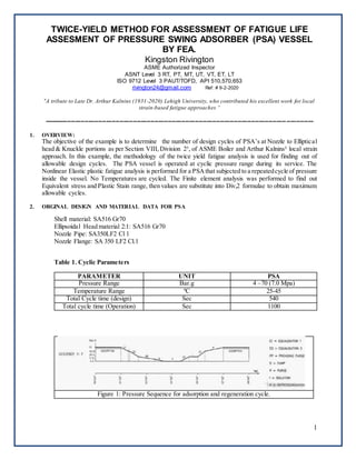
  • 1. 1 TWICE-YIELD METHOD FOR ASSESSMENT OF FATIGUE LIFE ASSESMENT OF PRESSURE SWING ADSORBER (PSA) VESSEL BY FEA. Kingston Rivington ASME Authorized Inspector ASNT Level 3 RT, PT, MT, UT, VT, ET, LT ISO 9712 Level 3 PAUT/TOFD, API 510,570,653 rivington24@gmail.com Ref: # 9-2-2020 “A tribute to Late Dr. Arthur Kalnins (1931-2020) Lehigh University, who contributed his excellent work for local strain-based fatigue approaches “ ----------------------------------------------------------------------------------------------------------------------------- -------------- 1. OVERVIEW: The objective of the example is to determine the number of design cycles of PSA’s at Nozzle to Elliptical head & Knuckle portions as per Section VIII, Division 2³, of ASME Boiler and Arthur Kalnins² local strain approach. In this example, the methodology of the twice yield fatigue analysis is used for finding out of allowable design cycles. The PSA vessel is operated at cyclic pressure range during its service. The Nonlinear Elastic plastic fatigue analysis is performed for a PSAthat subjected to a repeatedcycle of pressure inside the vessel. No Temperatures are cycled. The Finite element analysis was performed to find out Equivalent stress and Plastic Stain range, then values are substitute into Div,2 formulae to obtain maximum allowable cycles. 2. ORGINAL DESIGN AND MATERIAL DATA FOR PSA Shell material: SA516 Gr70 Ellipsoidal Head material 2:1: SA516 Gr70 Nozzle Pipe: SA350LF2 Cl 1 Nozzle Flange: SA 350 LF2 Cl.1 Table 1. Cyclic Parameters PARAMETER UNIT PSA Pressure Range Bar.g 4 –70 (7.0 Mpa) Temperature Range ºC 25-45 Total Cycle time (design) Sec 540 Total cycle time (Operation) Sec 1100 Figure 1: Pressure Sequence for adsorption and regeneration cycle.
  • 2. 2 Figure-2 Design drawing details for PSA 3.0 NOMENCLATURE nc s s = material parameter for the cyclic stress–strain curve model σa =total stress amplitude. σr =total stress range Kc s s = material parameter for the cyclic stress–strain curve model Δεpeq, k =equivalent plastic strain range for the kth loading condition or cycle. Δεeff , k =Effective Strain Range for the kth cycle. ΔSp k = equivalent stress Range Eya,k = value of modulus of elasticity of the material at the point under consideration ɛtr =total true strain range. ɛ pr =Plastic strain range. Salt =effective alternating equivalent stress amplitude 4.0 MATERIAL PROPERTIES FOR STRESS ANALYSIS According to 2019 Div. 2, paragraph 5.5.4.1(c ), a stabilized cyclic stress-strain curve shall be used. In this example, the cyclic curves provided in 2019 Div. 2, Part 3, Annex 3.D, paragraph 3.D.4, will be used. The cyclic curve is defined by equation (1).
  • 3. 3 The ɛta , total true strain amplitude to be cycled, The above equation is Ramberg-Osgood (R-O) format of the cyclic curve of equation (1) is not of the form that used in typical finite element programs that require a separation of elastic and elastic-plastic behaviour at a specified yield stress. Equation (1) gives no such yield stress separation. To find out the yield stress the following two methods are followed as described Arthur Kalnins² 1. Method A : To approximate this yield stress and modify the form of the curve, an offset of plastic strain, offset, (2.0e-5) is assumed and a line is drawn along the elastic slope of Ramberg-Osgood (R-O). The intersection of this line and the cyclic stress-strain curve is taken as the yield stress Figure-3 Ramberg-Osgood yield stress by curve shift method 2.Method B: The yield stress is calculated also from formula approach equation (2) For this example, the Method B formula approach has been chosen to find out yield stress. ncss = 0.126 Table 3-D.2M Cyclic Stress–Strain Curve Data Kcss = 693 Mpa Table 3-D.2M Cyclic Stress–Strain Curve Data offset= 2.0e-5 Table 3-D.1M Cyclic Stress–Strain Curve Data σy Yield stress = 177.25 Mpa
  • 4. 4 For the Twice-Yield Method, the curves are then converted to the hysteresis loop stress and strain curve form (strain range versus stress range). The plastic strain range is related to the stress range by the following equation (3) Table 2: Stress range versus plastic strain range Stress range (Mpa) Ey ncss Kcss εoffset Plastic Strain Range 355 1.98E+05 0.126 693 2.00E-05 0.00E+00 370 1.98E+05 0.126 693 2.00E-05 1.61E-05 380 1.98E+05 0.126 693 2.00E-05 2.93E-05 390 1.98E+05 0.126 693 2.00E-05 4.52E-05 400 1.98E+05 0.126 693 2.00E-05 6.42E-05 410 1.98E+05 0.126 693 2.00E-05 8.67E-05 420 1.98E+05 0.126 693 2.00E-05 1.13E-04 430 1.98E+05 0.126 693 2.00E-05 1.45E-04 440 1.98E+05 0.126 693 2.00E-05 1.82E-04 450 1.98E+05 0.126 693 2.00E-05 2.25E-04 460 1.98E+05 0.126 693 2.00E-05 2.76E-04 470 1.98E+05 0.126 693 2.00E-05 3.35E-04 480 1.98E+05 0.126 693 2.00E-05 4.03E-04 490 1.98E+05 0.126 693 2.00E-05 4.81E-04 500 1.98E+05 0.126 693 2.00E-05 5.72E-04 510 1.98E+05 0.126 693 2.00E-05 6.76E-04 520 1.98E+05 0.126 693 2.00E-05 7.96E-04 530 1.98E+05 0.126 693 2.00E-05 9.32E-04 540 1.98E+05 0.126 693 2.00E-05 1.09E-03 550 1.98E+05 0.126 693 2.00E-05 1.26E-03 560 1.98E+05 0.126 693 2.00E-05 1.46E-03 The Table 2 Stress range versus plastic strain range values are taken into material model. 5.0 MODEL AND LOADING The axisymmetric model 2D was taken from Example as 3D models are time consumed and complicated. The pressure load was modified to 7 Mpa (load at the cycle end point) and the nozzle thrust load(14 Mpa) was adjusted accordingly. The boundary conditions are X=0 ,Y=0.The multilinear Kinematic hardening Ansys workbench¹ model has been chosen. Figure 4.PSA model Figure 5. 2D model
  • 5. 5 Figure 6. Boundary condition 6.0 DETERMINATION OF EFFECTIVE STRAIN RANGE BY TWICE-YIELD METHOD The method is explained well by A. Kalnins² in his paper that if in the input the loading is specified as the loading range, and the cyclic stress range-strain range curve is used for the material model, then in the output the stress components are the stress component ranges and the strain components are the strain component ranges. Thus, in one FEA load step, for which the loading is specified from zero to that of the loading range, the output provides the stress and strain ranges that are needed for fatigue analysis Figure 4 : Twice Yield method with single load step 7.0 DETERMINATION OF DESIGN CYCLES
  • 6. 6 Figure 7. Von mises Equivalent stress range Figure 8. Equivalent plastic strain range a). To find out Effective Strain Ranges ΔSp k = equivalent stress (values obtained from Ansys output) Δεpeq, k = equivalent plastic strain range (values obtained from Ansys output) Eya,k = value of modulus of elasticity of the material Table-3 Component Location Eya,k ΔSp k Δεpeq, k Δεeff , k Nozzle Inside Radius 1.98E+05 515.84 8.34E-04 3.44E-03 Knuckle inside radius 1.98E+05 363.69 1.00E-05 1.85E-03
  • 7. 7 b. Determine the effective alternating equivalent stress for the cycle. Table- 4 Component Location Eya,k Δεeff , k Salt,K Nozzle Inside Radius 1.98E+05 3.44E-03 3.41E+02 Knuckle inside radius 1.98E+05 1.85E-03 1.83E+02 C. Determine the permissible number of cycles, Nk , for the alternating equivalent stress computed in Step b. Fatigue curves based on the materials of construction are provided in ASME Division VIII Div 2 Annex 3-F, 3-F.1, For Carbon, Low Alloy, Series 4XX, High Alloy, and High Tensile Strength Steels for temperatures not exceeding 371°C (700°F). The fatigue curve values may be interpolated for intermediate values of the ultimate tensile strength. ET = the material modulus of elasticity at the cycle temperature (1) For σuts ≤ 552 MPa (80 ksi) (see Figures 3-F.1M and 3-F.1) and for 48 MPa (7 ksi) ≤ Sa ≤ 3 999 MPa (580 ksi) 10ᵞ = 32.24 The above equation can be used. The design number of design cycles, N, can be computed from eq. (3-F.21) based on the parameter X calculated for the applicable material Table- 5 Component Location ET Sa Y X N cycles Nozzle Inside Radius 1.98E+05 3.41E+02 1.68E+00 3.70E+00 5032 Knuckle inside radius 1.98E+05 1.83E+02 1.41E+00 4.53E+00 33800 8.0 CONCLUSION Refer from table -5, nozzle to ellipsoidal head junction, would limit the design cycle life of PSA is 5032 cycles. References 1.ANSYS workbench (version 19.2) [FEA software] 2.Twice-Yield Method for Assessment of Fatigue Caused by Fast Thermal Transient According To 2007 Section Viii-Division 2 by Arthur Kalnins. 3.ASME Boiler & Pressure Vessel Code, Section VIII Div.2 2019 edition. 4.ASME PTB-3-2013