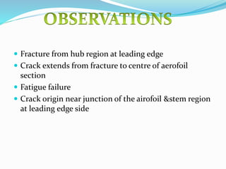
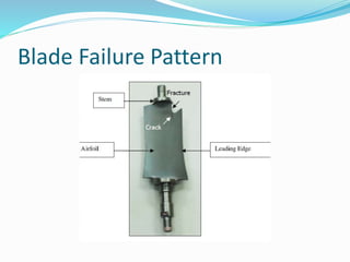
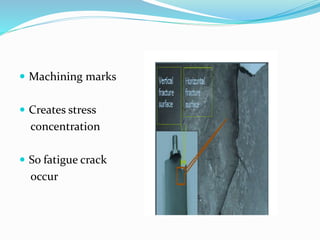
Ashutosh Kannawar
SKNCOE (Vadgaon)
TE Mech -2
SEAT NO:T120360925
 Propulsion system
 compressor
-Draw air&compress&deliver in combustion
chamber
 Aerodynamics
 Mechanical
 Thermal load
 Design ,Manufacturing
 Material selection
 Assembly etc
COMMON MODE OF FAILURE:
-Fatigue failure
 After disassembling the engine after a test run
 Take blade &analyse it, using visual&stereo binocular
method
 Stereo zoom microscope is used
 Fracture from hub region at leading edge
 Crack extends from fracture to centre of aerofoil
section
 Fatigue failure
 Crack origin near junction of the airofoil &stem region
at leading edge side
Blade Failure Pattern
 Machining marks
 Creates stress
concentration
 So fatigue crack
occur
 Compressor blade found to have failed in progressive
mode i.e.by fatigue
 Crack originate at blade hub-stem junction at the
leading edge side
 Presence of machining cracks is reason for failure
 To avoid stress concentration avoid machinig marks
 Avoid abrassive marks
 What are the blades:individual component which
makes turbine section of gas turbine & blades extract
energy from gas produced by combuster

 Different materials are used like nickel ,cobalt
 disadvantage of it :more complicated &costly.also
system must be strong to resist high pressure
 Desirable properties:corrosive resistant ,strong
 -cobalt (earlier used )
 -nickel (most common)
 Previosly cobalt is used
 Life is measured in hours before failure of blade
 Cobalt based blade have 50,000 hrs life
 Nickel based blade have 15,000 hrs life
 Also nickel based blades can work at high
temperature

 Failure cause :
 -microstructural changes
 -void formation
 -environmental effect
 Chemical damage
 Equipment –optical emission spectrometer
 EDS analyzer
 Three sections method(transverse)
 1)at root
 2)mid point
 3)top of airofoil

PROCEDURE:
 1)Take a blade which is failed
 2)Apply three sections method
 3)Put the blade below optical emission spectrometer
 4)Observe microstructure
 Hardness increases as we move towards fracture
 Ductility of the blade decreases due to high
temperature
 Chemical compossition of blade is same as IN-738LC
super alloy
 Gamma phase dissolve & disapper with increasing
distance from root
 Crack growth is interdendritic
 Hardness increases in fracture zone

Turbine blade faliure

  • 1.
    Ashutosh Kannawar SKNCOE (Vadgaon) TEMech -2 SEAT NO:T120360925
  • 2.
     Propulsion system compressor -Draw air&compress&deliver in combustion chamber
  • 3.
     Aerodynamics  Mechanical Thermal load  Design ,Manufacturing  Material selection  Assembly etc COMMON MODE OF FAILURE: -Fatigue failure
  • 4.
     After disassemblingthe engine after a test run  Take blade &analyse it, using visual&stereo binocular method  Stereo zoom microscope is used
  • 5.
     Fracture fromhub region at leading edge  Crack extends from fracture to centre of aerofoil section  Fatigue failure  Crack origin near junction of the airofoil &stem region at leading edge side
  • 6.
  • 7.
     Machining marks Creates stress concentration  So fatigue crack occur
  • 8.
     Compressor bladefound to have failed in progressive mode i.e.by fatigue  Crack originate at blade hub-stem junction at the leading edge side  Presence of machining cracks is reason for failure
  • 9.
     To avoidstress concentration avoid machinig marks  Avoid abrassive marks
  • 10.
     What arethe blades:individual component which makes turbine section of gas turbine & blades extract energy from gas produced by combuster   Different materials are used like nickel ,cobalt  disadvantage of it :more complicated &costly.also system must be strong to resist high pressure
  • 11.
     Desirable properties:corrosiveresistant ,strong  -cobalt (earlier used )  -nickel (most common)  Previosly cobalt is used
  • 12.
     Life ismeasured in hours before failure of blade  Cobalt based blade have 50,000 hrs life  Nickel based blade have 15,000 hrs life  Also nickel based blades can work at high temperature 
  • 13.
     Failure cause:  -microstructural changes  -void formation  -environmental effect  Chemical damage
  • 14.
     Equipment –opticalemission spectrometer  EDS analyzer  Three sections method(transverse)  1)at root  2)mid point  3)top of airofoil 
  • 15.
    PROCEDURE:  1)Take ablade which is failed  2)Apply three sections method  3)Put the blade below optical emission spectrometer  4)Observe microstructure
  • 16.
     Hardness increasesas we move towards fracture  Ductility of the blade decreases due to high temperature  Chemical compossition of blade is same as IN-738LC super alloy
  • 17.
     Gamma phasedissolve & disapper with increasing distance from root  Crack growth is interdendritic  Hardness increases in fracture zone