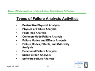
This document summarizes a presentation on failure analysis basics given to the Huntsville Regional Chapter of the International Council on Systems Engineering on April 26, 2002. The presentation covered the role of failure analysis in design and engineering, concepts and techniques in failure analysis like destructive physical analysis and fault tree analysis, and the future of failure analysis involving multidisciplinary teams. The goal was to develop an understanding of failure and review failure analysis methods.


![HHuunnttssvviillllee RReeggiioonnaall
CChhaapptteerr
April 26, 2002 55
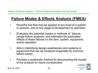
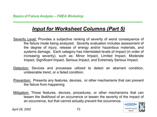
Basics of Failure Analysis – The Failure Modes and Effects Analysis (FMEA)
Process
Components-Level FMEAs
• Evaluates failure modes and effects at the components level
(i.e., smallest functioning unit) of design, engineering or
operation
• Addresses components [typically]as complete functioning
units (rather than as parts)
• Facilitates analysis of complex components by subdividing
the component into operational subcomponents
• Provides evaluation of probability (likelihood) and frequency
(rate) of failure](https://image.slidesharecdn.com/basicsoffailureanalysisevolve-140705174129-phpapp01/85/Basics-of-Failure-Analysis-55-320.jpg)


![Attack surfaces and attack tress[inform]](https://cdn.slidesharecdn.com/ss_thumbnails/lecture03-260108015941-a4dee53b-thumbnail.jpg?width=640&height=640&fit=bounds)


