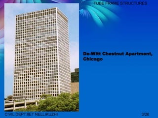
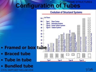
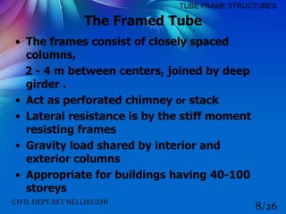
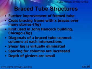
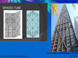
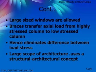
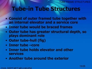
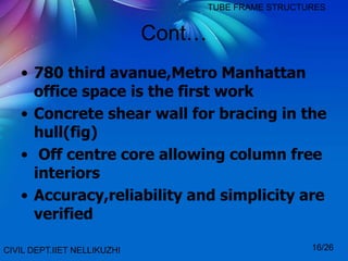
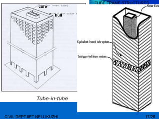
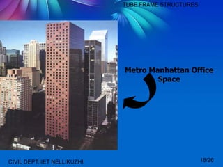
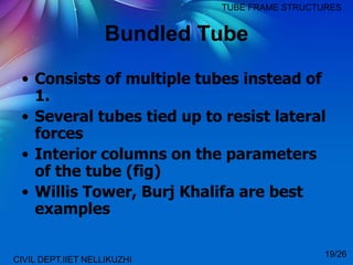
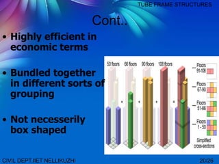
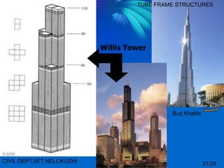
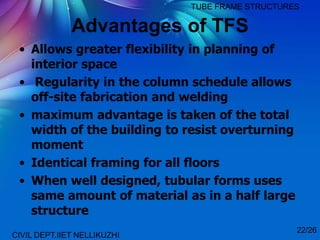
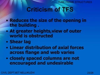
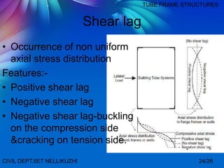
The document discusses tube frame structures for tall buildings. Tube frame structures were introduced by Fazlur Khan and involve a hollow cantilever tube perpendicular to the ground. They allow for buildings over 40 stories tall with configurations including framed tubes, braced tubes, tube-in-tube, and bundled tubes. Tube frame structures provide benefits like increased structural rigidity and regular column placement but also have disadvantages like reduced window size and occurrence of shear lag effects.
Tube structures and its type with comparison .Udayram Patil
Hollow tube section always provide greater strength. So the same concept is applied to the building. Tubed system is designed to act like a three dimensional hollow tube structure which result in increased load resistance .
One of the most efficient structural systems against heavy wind loads is the bundled tube structural system
The first person to implement the bundled tube structural system was Fazlur Rahman Khan from Dhaka, Bangladesh with the design of the DeWitt-Chestnut Apartments in Chicago, Illinois.
The bundled tube structure meant that "buildings no longer need be boxlike in appearance: they could become sculpture." Hybrids. Hybrids include a varied category of structures where the basic concept of tube is used, and supplemented by other structural support(s).
framed tube structure
structure tube furniture
structure tube canada
tube structural system
tube structure design
tube frame building kits
tube structure buildings
tube framed buildings
interesting civil engineering topics
civil engineering topics for presentation
seminar topics pdf
best seminar topics for civil engineering
civil seminar topics ppt
civil engineering seminar topics 2019
seminar topics for mechanical engineers
mechanical engineering seminar topics 2018
High Rise Building Structure Systems Types
Slide Contents :
INTRODUCTION
INTRODUCTION TO HIGH-RISE DESIGN
DEMANDS FOR HIGH RISE BUILDING
MATERIAL
TYPES OF SYSTEMS
CONSTRUCTIONAL DETAILS
ADVANTAGES AND DISADVANTAGES
A short and elaborate Case Study on High Rise Buildings for the course of Advanced Building Construction from students of 8th Semester Architecture at VNIT, Nagpur (January- April 2017)
Video Lecture: https://youtu.be/zoj6DYMvg2I
Structural System in High Rise building or Tall Building
Emporis standards-
“A multi-story structure between 35-100 meters tall, or a building of unknown
height from 12-39 floors is termed as high rise.
The International Conference on Fire Safety –
"any structure where the height can have a serious impact on evacuation“
Massachusetts, United States General Laws –
A high-rise is being higher than 70 feet (21 m).
Buildings higher than 100m is termed as skyscraper according to emporis.
Buildings 300m or higher is termed as super tall and buildings 600m or taller is termed as mega-tall.
While Designing a High rise Load & Structural Analysis is major factor to consider. Here we analyzed some data and try to describe briefly. We hope that it will help you lot :) Done by Neeti Lamic, Bayezid, Sykot Hasan
The tube is the name given to the systems where in order to resist lateral loads (wind, seismic, etc.) a building is designed to act like a three-dimensional hollow tube. The system was introduced by Fazlur Rahman Khan while at Skidmore, Owings and Merrill's (SOM) Chicago office. The first example of the tube’s use is the 43-story Khan-designed DeWitt-Chestnut Apartment Building in Chicago, Illinois, completed in 1963.
The system can be constructed using steel, concrete, or composite construction (the discrete use of both steel and concrete). It can be used for office, apartment and mixed-use buildings. Most buildings in excess of 40 stories constructed in the United States since the 1960s are of this structural type. The tube system concept is based on the idea that a building can be designed to resist lateral loads by designing it as a hollow cantilever perpendicular to the ground.
In the simplest incarnation of the tube, the perimeter of the exterior consists of closely spaced columns that are tied together with deep beams through moment connections. This assembly of columns and beams forms a rigid frame that amounts to a dense and strong structural wall along the exterior of the building.
This exterior framing is designed sufficiently strong to resist all lateral loads on the building, thereby allowing the interior of the building to be simply framed for gravity loads. Interior columns are comparatively few and located at the core.
The distance between the exterior and the core frames is spanned with beams or trusses. This maximizes the effectiveness of the perimeter tube by transferring some of the gravity loads within the structure to it and increases its ability to resist overturning due to lateral loads.
Since 1963, a new structural system of framed tubes appeared in skyscraper design and construction.
Fazlur Khan defined the framed tube structure as "a three dimensional space structure composed of three, four, or possibly more frames, braced frames, or shear walls, joined at or near their edges to form a vertical tube-like structural system capable of resisting lateral forces in any direction by cantilevering from the foundation."Closely spaced interconnected exterior columns form the tube. Horizontal loads, for example wind, are supported by the structure as a whole. About half the exterior surface is available for windows. Framed tubes allow fewer interior columns, and so create more usable floor space. Where larger openings like garage doors are required, the tube frame must be interrupted, with transfer girders used to maintain structural integrity.
The first building to apply the tube-frame construction was the DeWitt-Chestnut apartment building which Khan designed(1963) and was completed in Chicago by 1965. This laid the foundations for the tube structures of many other later skyscrapers, including his own John Hancock Center and Willis Tower, and can been seen in the construction of the World Trade Cente
Structural systems in high rise building and analysis methodsDP NITHIN
This presentation is about the structural systems in tall buildings and also consists of overview of methods of analysis in tall buildings like linear and non linear seismic analysis.
CFD Simulation of By-pass Flow in a HRSG module by R&R Consult.pptxR&R Consult
CFD analysis is incredibly effective at solving mysteries and improving the performance of complex systems!
Here's a great example: At a large natural gas-fired power plant, where they use waste heat to generate steam and energy, they were puzzled that their boiler wasn't producing as much steam as expected.
R&R and Tetra Engineering Group Inc. were asked to solve the issue with reduced steam production.
An inspection had shown that a significant amount of hot flue gas was bypassing the boiler tubes, where the heat was supposed to be transferred.
R&R Consult conducted a CFD analysis, which revealed that 6.3% of the flue gas was bypassing the boiler tubes without transferring heat. The analysis also showed that the flue gas was instead being directed along the sides of the boiler and between the modules that were supposed to capture the heat. This was the cause of the reduced performance.
Based on our results, Tetra Engineering installed covering plates to reduce the bypass flow. This improved the boiler's performance and increased electricity production.
It is always satisfying when we can help solve complex challenges like this. Do your systems also need a check-up or optimization? Give us a call!
Work done in cooperation with James Malloy and David Moelling from Tetra Engineering.
More examples of our work https://www.r-r-consult.dk/en/cases-en/
Immunizing Image Classifiers Against Localized Adversary Attacksgerogepatton
This paper addresses the vulnerability of deep learning models, particularly convolutional neural networks
(CNN)s, to adversarial attacks and presents a proactive training technique designed to counter them. We
introduce a novel volumization algorithm, which transforms 2D images into 3D volumetric representations.
When combined with 3D convolution and deep curriculum learning optimization (CLO), itsignificantly improves
the immunity of models against localized universal attacks by up to 40%. We evaluate our proposed approach
using contemporary CNN architectures and the modified Canadian Institute for Advanced Research (CIFAR-10
and CIFAR-100) and ImageNet Large Scale Visual Recognition Challenge (ILSVRC12) datasets, showcasing
accuracy improvements over previous techniques. The results indicate that the combination of the volumetric
input and curriculum learning holds significant promise for mitigating adversarial attacks without necessitating
adversary training.
About
Indigenized remote control interface card suitable for MAFI system CCR equipment. Compatible for IDM8000 CCR. Backplane mounted serial and TCP/Ethernet communication module for CCR remote access. IDM 8000 CCR remote control on serial and TCP protocol.
• Remote control: Parallel or serial interface.
• Compatible with MAFI CCR system.
• Compatible with IDM8000 CCR.
• Compatible with Backplane mount serial communication.
• Compatible with commercial and Defence aviation CCR system.
• Remote control system for accessing CCR and allied system over serial or TCP.
• Indigenized local Support/presence in India.
• Easy in configuration using DIP switches.
Technical Specifications
Indigenized remote control interface card suitable for MAFI system CCR equipment. Compatible for IDM8000 CCR. Backplane mounted serial and TCP/Ethernet communication module for CCR remote access. IDM 8000 CCR remote control on serial and TCP protocol.
Key Features
Indigenized remote control interface card suitable for MAFI system CCR equipment. Compatible for IDM8000 CCR. Backplane mounted serial and TCP/Ethernet communication module for CCR remote access. IDM 8000 CCR remote control on serial and TCP protocol.
• Remote control: Parallel or serial interface
• Compatible with MAFI CCR system
• Copatiable with IDM8000 CCR
• Compatible with Backplane mount serial communication.
• Compatible with commercial and Defence aviation CCR system.
• Remote control system for accessing CCR and allied system over serial or TCP.
• Indigenized local Support/presence in India.
Application
• Remote control: Parallel or serial interface.
• Compatible with MAFI CCR system.
• Compatible with IDM8000 CCR.
• Compatible with Backplane mount serial communication.
• Compatible with commercial and Defence aviation CCR system.
• Remote control system for accessing CCR and allied system over serial or TCP.
• Indigenized local Support/presence in India.
• Easy in configuration using DIP switches.
Hierarchical Digital Twin of a Naval Power SystemKerry Sado
A hierarchical digital twin of a Naval DC power system has been developed and experimentally verified. Similar to other state-of-the-art digital twins, this technology creates a digital replica of the physical system executed in real-time or faster, which can modify hardware controls. However, its advantage stems from distributing computational efforts by utilizing a hierarchical structure composed of lower-level digital twin blocks and a higher-level system digital twin. Each digital twin block is associated with a physical subsystem of the hardware and communicates with a singular system digital twin, which creates a system-level response. By extracting information from each level of the hierarchy, power system controls of the hardware were reconfigured autonomously. This hierarchical digital twin development offers several advantages over other digital twins, particularly in the field of naval power systems. The hierarchical structure allows for greater computational efficiency and scalability while the ability to autonomously reconfigure hardware controls offers increased flexibility and responsiveness. The hierarchical decomposition and models utilized were well aligned with the physical twin, as indicated by the maximum deviations between the developed digital twin hierarchy and the hardware.
Explore the innovative world of trenchless pipe repair with our comprehensive guide, "The Benefits and Techniques of Trenchless Pipe Repair." This document delves into the modern methods of repairing underground pipes without the need for extensive excavation, highlighting the numerous advantages and the latest techniques used in the industry.
Learn about the cost savings, reduced environmental impact, and minimal disruption associated with trenchless technology. Discover detailed explanations of popular techniques such as pipe bursting, cured-in-place pipe (CIPP) lining, and directional drilling. Understand how these methods can be applied to various types of infrastructure, from residential plumbing to large-scale municipal systems.
Ideal for homeowners, contractors, engineers, and anyone interested in modern plumbing solutions, this guide provides valuable insights into why trenchless pipe repair is becoming the preferred choice for pipe rehabilitation. Stay informed about the latest advancements and best practices in the field.
3. CONTENTS
• Introduction
• Need for high rise buildings
• Different configurations
• Advantages
• Disadvantages
• Brief explanation of shear lag
• Conclusion
• References
1/26
TUBE FRAME STRUCTURES
CIVIL DEPT.IIET NELLIKUZHI
4. INTRODUCTION
• Introduced by Fazalur Khan,Dhaka
Bangladesh
• Hollow cantilever perpendicular to
the ground
• Buildings in excess of 40 stories
• A 43-story Khan-designed De-Witt
Chestnut Apartment in Chicago
• Steel, concrete, or composite
construction
TUBE FRAME STRUCTURES
CIVIL DEPT.IIET NELLIKUZHI 2/26
6. Need for tall structure
• Increase in building height
• Slenderness
• Building weight reduction
• Limited availability of land
• Rapid increase in cost of land
4/26CIVIL DEPT.IIET NELLIKUZHI
TUBE FRAME STRUCTURES
7. CONCEPT OF TUBULAR
SYSTEM
• Design of strength, rigid and stable
structures
• Largely economic solution
• Building designed for resisting lateral loads
• Hollow cantilever perpendicular to ground
• Incarnation of the tubes
• Exterior-Columns and beams forms a rigid
frame
• Interior-simply framed for gravity loads
• 50% of windows on exterior wall surface 5/26
CIVIL DEPT.IIET NELLIKUZHI
TUBE FRAME STRUCTURES
8. Defining tube frame
• Predict the structural behavior
• Replace 3D system by equivalent
plane frame
• Analysed by conventional methods
• Comparison of results- 15 story
Perspex model of the building
• Deciding the type of configuration
6/26CIVIL DEPT.IIET NELLIKUZHI
TUBE FRAME STRUCTURES
9. CIVIL DEPT.IIET NELLIKUZHI 7/26
TUBE FRAME STRUCTURES
Configuration of Tubes
• Framed or box tube
• Braced tube
• Tube in tube
• Bundled tube
10. The Framed Tube
• The frames consist of closely spaced
columns,
2 - 4 m between centers, joined by deep
girder .
• Act as perforated chimney or stack
• Lateral resistance is by the stiff moment
resisting frames
• Gravity load shared by interior and
exterior columns
• Appropriate for buildings having 40-100
storeys
CIVIL DEPT.IIET NELLIKUZHI
8/26
TUBE FRAME STRUCTURES
11. Tube frame structures
CIVIL DEPT.IIET NELLIKUZHI 9/26
Cont..
• Grid like facade structures and is repetious
• Use of prefabrication possible
• Larger distance of exterior column from
NA resists bending moment
• Economically attractive and possess
torsional rigidity
• Greater flexibility in space planning
• A well known example-World Trade Centre
12. CASE STUDY OF WORLD TRADE CENTRE
CIVIL DEPT.IIET NELLIKUZHI
10/26
TUBE FRAME STRUCTURES
• Architect:-Minoru
Yamasaki
• 110 story tower
• 415m in height
• 50,000 employees
and 80,000 visitors
daily
• Twin tower in
diagonal
juxtaposition
13. Cont…
• vertical extrusions of square plans
• The framed tube consist of 56 box steel
columns joint by moment resisting
connections
• The overall dimensions of framed tube
column are constant
• Wall thickness increases from top to
bottom to increse response to loads
CIVIL DEPT.IIET NELLIKUZHI 11/26
TUBE FRAME STRUCTURES
14. CIVIL DEPT.IIET NELLIKUZHI 12/26
TUBE FRAME STRUCTURES
Braced Tube Structures
• Further improvement of framed tube
• Cross bracing frame with x braces over
many stories-(fig)
• First used in John Hancock building,
Chicago-(fig)
• Diagonals of a braced tube connect
columns at each intersections
• Shear lag is virtually eliminated
• Spacing for columns are increased
• Depth of girders are small
16. Cont…
• Large sized windows are allowed
• Braces transfer axial load from highly
stressed column to low stressed
column
• Hence eliminates difference between
load stress
• Large scope of architecture .uses a
structural-architectural concept
CIVIL DEPT.IIET NELLIKUZHI
14/26
TUBE FRAME STRUCTURES
17. Tube-in Tube Structures
• Consist of outer framed tube together with
an internal elevator and a service core
• Inner tube would be braced frames
• Outer tube has greater structural depth, so
plays dominant role
• Outer tube-hull (fig)
• Inner tube –core
• Inner tube holds elevator and other
services
• Another tube around the exterior
15/26
TUBE FRAME STRUCTURES
18. Cont…
• 780 third avanue,Metro Manhattan
office space is the first work
• Concrete shear wall for bracing in the
hull(fig)
• Off centre core allowing column free
interiors
• Accuracy,reliability and simplicity are
verified
CIVIL DEPT.IIET NELLIKUZHI 16/26
TUBE FRAME STRUCTURES
21. Bundled Tube
• Consists of multiple tubes instead of
1.
• Several tubes tied up to resist lateral
forces
• Interior columns on the parameters
of the tube (fig)
• Willis Tower, Burj Khalifa are best
examples
CIVIL DEPT.IIET NELLIKUZHI
19/26
TUBE FRAME STRUCTURES
22. Cont..
• Highly efficient in
economic terms
• Bundled together
in different sorts of
grouping
• Not necesserily
box shaped
CIVIL DEPT.IIET NELLIKUZHI
TUBE FRAME STRUCTURES
20/26
24. Advantages of TFS
• Allows greater flexibility in planning of
interior space
• Regularity in the column schedule allows
off-site fabrication and welding
• maximum advantage is taken of the total
width of the building to resist overturning
moment
• Identical framing for all floors
• When well designed, tubular forms uses
same amount of material as in a half large
structure
CIVIL DEPT.IIET NELLIKUZHI
22/26
TUBE FRAME STRUCTURES
25. Criticism of TFS
• Reduces the size of the opening in
the building .
• At greater heights,view of outer
world is obstructed
• Shear lag
• Linear distribution of axial forces
across flange and web varies
• closely spaced columns are not
encouraged and undesirable
CIVIL DEPT.IIET NELLIKUZHI
TUBE FRAME STRUCTURES
23/26
26. Shear lag
• Occurrence of non uniform
axial stress distribution
Features:-
• Positive shear lag
• Negative shear lag
• Negative shear lag-buckling
on the compression side
&cracking on tension side.
CIVIL DEPT.IIET NELLIKUZHI
TUBE FRAME STRUCTURES
24/26
27. Conclusion
• The provision of adequate, stiffness,
particularly lateral stiffness is a major
consideration In the design of a tall
building hence TFS are engineers favorite
• But structural cost of the TFS may be high
with respect to conventional shear wall
structure
• so necessary to do research for cost
comparison between TFS and conventional
shear wall
CIVIL DEPT.IIET NELLIKUZHI
TUBE FRAME STRUCTURES
25/26
28. References
1. Er. Nahant Rana,et.al.” Structural Forms Systems for Tall Building
Structures,SSRJ”, International Journal Of Civil Engineering (SSRG IJCE),
September 2014volume issued4
2. Hardin J. Patel,et,al. “Braced Tube Structural System: A review”
International Journal of Scientific & Engineering Research, December-2015, ,
Volume 6, Issue 12.
3. R. Mahjoub,et,al, “Simple Analysis of Tube Frame System of Tall Building by
Using Deformation Functions”. Australian Journal of Basic and Applied
Sciences, February 2011. [324-332]
4. Reza Mahjoub,et.al“Analysis of Tube Frame System of Tall Building by
Using of Deformation Functions”. Australian Journal of Basic and Applied
Sciences, 5(8): 1475-1482, 2011.
5. Sharadrao Patil,et.al, “Shear Lag in Tube Structures”. IJISET - International
Journal of Innovative Science, Engineering & Technology, March (2015), Vol.
2 Issue 3,
CIVIL DEPT.IIET NELLIKUZHI 26/26
TUBE FRAME STRUCTURES