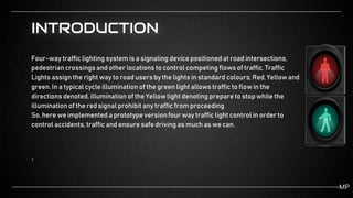
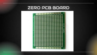
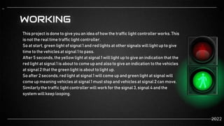
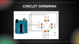
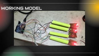
MINOR PROJECT
ON
4 WAY TRAFFIC LIGHT
CONTROL SYSTEM
PRESENTED BY—
ARUNABH VIKRAM GHOSH
ANURAG GHOSH
BHAVESH SAHU
S.SUNRESH
GUIDED BY—
Mr. ABHIJEET LAL
CONTENTS
● INTRODUCTION
● COMPONENTS
 ARDUINO UNO
 ZERO PCB BOARD
 JUMPER WIRES
 LEDs
● WORKING
● CIRCUIT DIAGRAM
● CODE
● WORKING MODEL
INTRODUCTION
Four-way traffic lighting system is a signaling device positioned at road intersections,
pedestrian crossings and other locations to control competing flows of traffic. Traffic
Lights assign the right way to road usersby the lights in standard colours;Red, Yellowand
green. In a typical cycle illumination of the green light allows traffic to flow in the
directions denoted,illumination of the Yellowlight denoting prepare to stop while the
illumination of the red signal prohibit any traffic from proceeding
So, here we implemented a prototype versionfour way traffic light control in order to
control accidents, traffic and ensure safe driving as much as we can.
.
MP
COMPONENTS
AUDRINO UNO
ARDUINO UNO
● Arduino UNOis a low-cost, flexible,and easy-to-useprogrammable open-source
microcontroller board that can be integrated into a variety of electronic projects. This
board can be interfaced with other Arduino boards,Arduino shields,Raspberry Pi boards
and can control relays,LEDs, servos,and motors as an output.
● Arduino UNO is a microcontroller board based on the ATmega328P. It has 14 digital input/outputpins (of
which 6 can be used as PWM outputs),6 analog inputs, a 16 MHz ceramic resonator, a USB connection, a
power jack, an ICSPheader and a resetbutton. It contains everything neededto support the
microcontroller; simply connect it to a computerwith a USB cable or power it with a AC-to-DCadapter or
batteryto get started.You can tinker with your UNO without worrying too much about doing something
wrong, worst case scenario you can replace the chip for a fewdollars and start over again.
ZERO PCB BOARD
ZERO PCB BOARD
● Zero PCB is basically a general-purpose printed circuit board (PCB), also
known as perfboard or DOT PCB. It is a thin rigid copper sheet with holes pre-
drilled at standard intervals across a grid with 2.54mm (0.1-inch) spacing
between holes. Each hole is encircled by a round or square copper pad so that
component lead can be inserted into the hole and soldered around the pad
without short-circuiting the nearby pads and other leads. For connecting the
lead of component with another lead, solder these together or join these using a
suitable conducting wire.
JUMPER WIRES
JUMPER WIRES
Jumper wires are simply wires that have connector pins at each end, allowing them to be used
to connect two points to each other without soldering.Jumper wires are typically used
with breadboardsand other prototyping tools in order to make it easy to change a circuit as
needed.Fairly simple.In fact, it doesn’t get much more basic than jumper wires.
Though jumper wires come in a variety of colors,the colors don’t actually mean anything.
This means that a red jumper wire is technically the same as a black one.
But the colors can be used to your advantage in order to differentiate between types of
connections, such as ground or power.
LEDs
WORKING
This project is done to give you an idea of how the traffic light controller works. This
is not the real time traffic light controller.
So at start, green light of signal 1 and red lights at other signals will light up to give
time to the vehicles at signal 1 to pass.
After 5 seconds,the yellow light at signal 1 will light up to give an indication that the
red light at signal 1 is about to come up and also to give an indication to the vehicles
at signal 2 that the green light is about to light up.
So after 2 seconds,red light at signal 1 will come up and green light at signal will
come up meaning vehicles at signal 1 must stop and vehicles at signal 2 can move.
Similarly the traffic light controller will work for the signal 3, signal 4 and the
system will keep looping.
..
2022
CIRCUIT DIAGRAM
WORKING MODEL

Four_way_Traffic_Light for mini project.pptx

  • 1.
    MINOR PROJECT ON 4 WAYTRAFFIC LIGHT CONTROL SYSTEM PRESENTED BY— ARUNABH VIKRAM GHOSH ANURAG GHOSH BHAVESH SAHU S.SUNRESH GUIDED BY— Mr. ABHIJEET LAL
  • 2.
    CONTENTS ● INTRODUCTION ● COMPONENTS ARDUINO UNO  ZERO PCB BOARD  JUMPER WIRES  LEDs ● WORKING ● CIRCUIT DIAGRAM ● CODE ● WORKING MODEL
  • 3.
    INTRODUCTION Four-way traffic lightingsystem is a signaling device positioned at road intersections, pedestrian crossings and other locations to control competing flows of traffic. Traffic Lights assign the right way to road usersby the lights in standard colours;Red, Yellowand green. In a typical cycle illumination of the green light allows traffic to flow in the directions denoted,illumination of the Yellowlight denoting prepare to stop while the illumination of the red signal prohibit any traffic from proceeding So, here we implemented a prototype versionfour way traffic light control in order to control accidents, traffic and ensure safe driving as much as we can. . MP
  • 4.
  • 5.
    ARDUINO UNO ● ArduinoUNOis a low-cost, flexible,and easy-to-useprogrammable open-source microcontroller board that can be integrated into a variety of electronic projects. This board can be interfaced with other Arduino boards,Arduino shields,Raspberry Pi boards and can control relays,LEDs, servos,and motors as an output. ● Arduino UNO is a microcontroller board based on the ATmega328P. It has 14 digital input/outputpins (of which 6 can be used as PWM outputs),6 analog inputs, a 16 MHz ceramic resonator, a USB connection, a power jack, an ICSPheader and a resetbutton. It contains everything neededto support the microcontroller; simply connect it to a computerwith a USB cable or power it with a AC-to-DCadapter or batteryto get started.You can tinker with your UNO without worrying too much about doing something wrong, worst case scenario you can replace the chip for a fewdollars and start over again.
  • 6.
  • 7.
    ZERO PCB BOARD ●Zero PCB is basically a general-purpose printed circuit board (PCB), also known as perfboard or DOT PCB. It is a thin rigid copper sheet with holes pre- drilled at standard intervals across a grid with 2.54mm (0.1-inch) spacing between holes. Each hole is encircled by a round or square copper pad so that component lead can be inserted into the hole and soldered around the pad without short-circuiting the nearby pads and other leads. For connecting the lead of component with another lead, solder these together or join these using a suitable conducting wire.
  • 8.
  • 9.
    JUMPER WIRES Jumper wiresare simply wires that have connector pins at each end, allowing them to be used to connect two points to each other without soldering.Jumper wires are typically used with breadboardsand other prototyping tools in order to make it easy to change a circuit as needed.Fairly simple.In fact, it doesn’t get much more basic than jumper wires. Though jumper wires come in a variety of colors,the colors don’t actually mean anything. This means that a red jumper wire is technically the same as a black one. But the colors can be used to your advantage in order to differentiate between types of connections, such as ground or power.
  • 10.
  • 11.
    WORKING This project isdone to give you an idea of how the traffic light controller works. This is not the real time traffic light controller. So at start, green light of signal 1 and red lights at other signals will light up to give time to the vehicles at signal 1 to pass. After 5 seconds,the yellow light at signal 1 will light up to give an indication that the red light at signal 1 is about to come up and also to give an indication to the vehicles at signal 2 that the green light is about to light up. So after 2 seconds,red light at signal 1 will come up and green light at signal will come up meaning vehicles at signal 1 must stop and vehicles at signal 2 can move. Similarly the traffic light controller will work for the signal 3, signal 4 and the system will keep looping. .. 2022
  • 12.
  • 13.